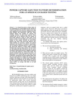
The document proposes a method to determine power-safe test patterns for at-speed scan-based testing to address excessive capture power issues. It involves two main processes: 1) test pattern refinement process which refines existing power-safe patterns to detect faults detected by power-risky patterns while satisfying power constraints, and 2) low-power test pattern regeneration process which generates new power-safe patterns if faults remain undetected after refinement. Experimental results show the method can detect over 75% of power-risky faults through refinement with up to 12.76% reduction in test data volume without loss of fault coverage.
![structures or by adding some additional
hardware to the CUT.
I. In scan chain segmentation methods are
proposed to reduce both shift and capture
power.
II. In a partial launch on- capture (LOC) scheme
is proposed to reduce the capture power,
which allows only partial scan cells to be
activated during the capture cycle.
Advantages:
1. Some clock gating schemes have also been
proposed to limit the test power
consumption.
2. They effectively reduce test power.
Disadvantages:
1. They may increase circuit area
2. Degrade circuit performance
3. They may be incompatible with existing
design flows
b) software-based methods attempt to generate
power safe test patterns that will not consume
excess power during testing by modifying the
traditional automatic test pattern generation
(ATPG) procedure or by modifying
predetermined test sets. These methods are
generally based on the X-filling technique to
assign fixed logic values to don’t care bits (X-
bits) in test patterns to minimize test power
dissipation.
c) Instead of modifying the ATPG procedure, some
post-ATPG methods modify a given test set by
using X-filling to reduce as much test power as
possible [7], [10], [16] or to satisfy the power
constraints [6], [21], [26]. Butler et al. [16]
propose a method, named adjacency fill, which
assigns deterministic values to the X-bits in line
with the adjacent bit values to reduce shift
power.
d) Another method to reduce the capture power is
to use the circuit’s steady states to fill X-bits [7].
This method, called ACF in [7], first fills X-bit
randomly. Then, it applies a number of
functional clock cycles starting from the scan-in
state of a test.
e) Vector to obtain the final states and uses these
states to fill the X-bits to get more realistic
patterns. Although both the Preferred Fill and
the ACF methods can quickly assign the X-bits
in PPI, they cannot ensure capture power
safety because they do not consider the power
constraint of the circuit. Another problem with
the above two methods is that they try to
assign values to all X-bits in all test patterns to
reduce test power as much as possible.
However, not all of the test patterns are power-
risky [19].
I. Devanathan et al.and Wu et al. modified the
PODEM-based ATPG procedure by adding
some power constraints to the back trace and
dynamic compaction processes to directly
generate power-safe test sets.
II. In a low-capture power (LCP) X-filling method
is proposed and incorporated into the dynamic
compaction process of the test generation flow
to reduce the capture power.
III. Although these methods can achieve a large
reduction in capture power, they often increase
the test data volume in comparison with that
produced by conventional at-speed scan test
methods due to the fact that during the dynamic
compaction process, many X-bits that can be
assigned to detect more faults are reserved to
reduce capture power.
II METHODS TO REDUCE CAPTURE
POWER
1. Instead of modifying the ATPG procedure,
some post-ATPG methods modify a given
test set by using X-filling to reduce as
much test power as possible or to satisfy
the power constraints.
a) Adjacency fill assigns deterministic values
to the X-bits in line with the adjacent bit
values to reduce shift power.
eg,-given the test pattern (1, X, X, 1, 0), the
X-bits in this pattern are filled as (1, 1, 1,
1, 0).
b) The circuit’s steady states to fill X-bits
(ACF), this method first fills X-bit
randomly. Then, it applies a number of
functional clock cycles starting from the
scan-in state of a test vector to obtain the
final states and uses these states to fill the
X-bits to get more realistic patterns.
INTERNATIONAL CONFERENCE ON CIVIL AND MECHANICAL ENGINEERING, ICCME-2014
INTERNATIONAL ASSOCIATION OF ENGINEERING & TECHNOLOGY FOR SKILL DEVELOPMENT www.iaetsd.in
24
ISBN:378-26-138420-0230](https://image.slidesharecdn.com/iaetsd-powercapturesafetestpatterndetermination-150420110913-conversion-gate01/85/Iaetsd-power-capture-safe-test-pattern-determination-2-320.jpg)
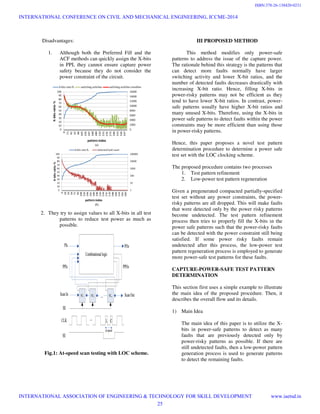
![2) Overall Flow of Proposed Procedure
Based on the main idea, a technique is
proposed to determine a test set such that the
power constraint is satisfied and the test data
inflation is minimized
3) Algorithm for Test Pattern Refinement Process
1. The goal of the test pattern refinement
process is to utilize the X-bits in power-
safe patterns to to utilize the X-bits in
power-safe patterns to This process ends
when there are no remaining faults
In Fr or all the power-safe patterns in Ts have
been refined.
4) Algorithm for Low Power Test Generation
Process
The low-power test generation process
attempts to generate a new power-safe test
set to detect all the undetected faults and
minimize the test data inflation at the same
time. In order to achieve this goal, this
process uses a dynamic data compression
flow [20]
IV CONCLUSION AND FUTURE SCOPE
This paper proposed a novel capture-power-safe test
pattern determination procedure to address the
capture power problem. Unlike previous methods,
the test pattern refinement processing the proposed
procedure refines power-safe patterns to detect the
power-risky faults and discards the power-risky
patterns to ensure the capture power safety. The
capture power of newly generated patterns is also
guaranteed to be under the power constraints. The
experimental results show that more than 75% of
power-risky faults can be detected by refining the
power safe patterns, and that the required test data
volumes can be reduced by 12.76% on average
under the appropriate power constraints without
fault coverage loss.
References:
[1] N. Ahmed, M. Tehranipoor, and V. Jayaram,
“Transition delay fault test
pattern generation considering supply voltage noise
in a SOC design,”
in Proc. Design Autom. Conf., 2007, pp. 533–538
[2] Y. Bonhomme, P. Girard, L. Guiller, C.
Landrault, and S. Pravossoudovitch,
“A gated clock scheme for low power scan testing
of logic
ICs or embedded cores, ” in Proc. Asian Test Symp.,
2001, pp. 253–258.
[3] K. Enokimoto, X. Wen, Y. Yamato, K. Miyase,
H. Sone, S. Kajihara,
M. Aso, and H. Furukawa, “CAT: A critical-area-
targeted test set
modification scheme for reducing launch switching
activity in at-speed
scan testing,” in Proc. Asian Test Symp., 2009, pp.
99–104
[4] T.-C. Huang and K.-J. Lee, “A token scan
architecture for low power
testing,” in Proc. Int. Test Conf., 2001, pp. 660–669.
INTERNATIONAL CONFERENCE ON CIVIL AND MECHANICAL ENGINEERING, ICCME-2014
INTERNATIONAL ASSOCIATION OF ENGINEERING & TECHNOLOGY FOR SKILL DEVELOPMENT www.iaetsd.in
26
ISBN:378-26-138420-0232](https://image.slidesharecdn.com/iaetsd-powercapturesafetestpatterndetermination-150420110913-conversion-gate01/85/Iaetsd-power-capture-safe-test-pattern-determination-4-320.jpg)
![[5] K.-J. Lee, S.-J. Hsu, and C.-M. Ho, “Test power
reduction with multiple
capture orders,” in Proc. Asian Test Symp., 2004,
pp. 26–31.
[6] J. Li, Q. Xu, Y. Hu, and X. Li, “X-Filling for
simultaneous shift- and
capture-power reduction in at-speed scan-based
testing,” IEEE Trans.
Very Large Scale Integr. Syst., vol. 18, no. 7, pp.
1081–1092, Jul.
2010.
[7] E. K. Moghaddam, J. Rajski, S. M. Reddy, and
M. Kassab, “At-speed
scan test with low switching activity,” in Proc. VLSI
Test Symp., 2010,
pp. 177–182.
[8] K. Miyase and S. Kajihara, “XID: Don’t care
identification of test
patterns for combinational circuits,” IEEE Trans.
Comput. Aided Design
Integr. Circuits Syst., vol. 23, no. 2, pp. 321–326,
Feb. 2004.
[9] I. Pomeranz and S. M. Reddy, “Switching
activity as a test compaction
heuristic for transition faults,” IEEE Trans. Very
Large Scale Integr. Syst.,
vol. 18, no. 9, pp. 1357–1361, Sep. 2010.
[10] S. Remersaro, X. Lin, Z. Zhang, S. M. Reddy,
I. Pomeranz, and
J. Rajski, “Preferred fill: A scalable method to
reduce capture power
for scan based designs,” in Proc. Int. Test Conf.,
2006, pp. 1–10.
INTERNATIONAL CONFERENCE ON CIVIL AND MECHANICAL ENGINEERING, ICCME-2014
INTERNATIONAL ASSOCIATION OF ENGINEERING & TECHNOLOGY FOR SKILL DEVELOPMENT www.iaetsd.in
27
ISBN:378-26-138420-0233](https://image.slidesharecdn.com/iaetsd-powercapturesafetestpatterndetermination-150420110913-conversion-gate01/85/Iaetsd-power-capture-safe-test-pattern-determination-5-320.jpg)