Download to read offline
![P.T.Sairam Int. Journal of Engineering Research and Applications www.ijera.com
ISSN : 2248-9622, Vol. 4, Issue 11(Version - 6), November 2014, pp.07-13
www.ijera.com 7 | P a g e
Reduced Test Pattern Generation of Multiple SIC Vectors with Input and Output Delay Faults P.T.Sairam*, B.Ratnaraju ** *PG student (VLSID), KIET,Kakinada, India, ** Associate Professor, ECE Dept, KIET, Kakinada, India, ABSTRACT In recent years, the design for low power has become one of the greatest challenges in high-performance very large scale integration (VLSI) design. Most of the methods focus on the power consumption during normal mode operation, while test mode operation has not normally been a predominant concern. However, it has been found that the power consumed during test mode operation is often much higher than during normal mode operation [1]. This is because most of the consumed power results from the switching activity in the nodes of the circuit under test (CUT), which is much higher during test mode than during normal mode operation [1]–[3]. In the proposed pattern, each generated vector applied to each scan chain is an SIC vector, which can minimize the input transition and reduce test power. In VLSI testing, power reduction is achieved by increasing the correlation between consecutive test patterns.
Keywords - Built in Self Test (BIST) , Johnson ring counter, MSIC patterns, Test Pattern Generator (TPG), Circuit Under Test (CUT).
I. INTRODUCTION
A fault is a representation of a defect reflecting a physical condition that causes a circuit to fail to perform in a required manner. To test a circuit with n inputs and m outputs, a set of input patterns is applied to the circuit under test (CUT), and its responses are compared to the known good responses of a fault-free circuit. Each input pattern is called a test vector. In order to completely test a circuit, many test patterns are required; however, it is difficult to know how many test vectors are needed to guarantee a satisfactory reject rate. If the CUT is an n-input combinational logic circuit, we can apply all 2 n possible input patterns for testing stuck-at faults; this approach is called exhaustive testing. Unfortunately, exhaustive testing is not practical when n is large. BUILT-IN SELF-TEST (BIST) techniques can effectively reduce the difficulty and complexity of VLSI testing, by introducing on-chip test hardware into the circuit- under-test (CUT). In conservative BIST architectures, the linear feedback shift register (LFSR) is commonly used in the test pattern generators (TPGs) and output response analyzers. A major disadvantage of these architectures is that the pseudorandom patterns generated by the LFSR provide to considerably high switching behavior in the CUT [1], which can cause too much power dissipation. They can also spoil the circuit and decrease product yield and life span [2], [3]. In addition, the LFSR usually needs to generate very lengthy pseudorandom sequences in order to attain the target fault coverage in nanometer technology.
II. PRELIMINARIES A. Prior Work
Several advanced BIST techniques have been studied and applied. The first class is the LFSR tuning. Girard et al. analyzed the impact of an LFSR’s polynomial and seed selection on the CUT’s switching activity, and proposed a method to select the LFSR seed for energy reduction [4]. The second class is low-power TPGs. One approach is to design low-transition TPGs. Wang and Gupta used two LFSRs of different speeds to control those inputs that have elevated transition densities [5]. Corno et al. provided a low power TPG based on the cellular automata to reduce the test power in combinational circuits [6]. Another approach focuses on modifying LFSRs. The scheme in [7] reduces the power in the CUT in general and clock tree in particular. In [8], a low-power BIST for data path architecture is proposed, which is circuit dependent. However, this dependency implies that non detecting subsequences must be determined for each circuit test sequence. Bonhomme et al. [9] used a clock gating technique where two non overlapping clocks control the odd and even scan cells of the scan chain so that the shift power dissipation is reduced by a factor of two. The ring generator [10] can generate a single-input change (SIC) sequence which can effectively reduce test power. The third approach aims to reduce the dynamic power dissipation during scan shift through gating of the outputs of a portion of the scan cells. Bhunia et al. [11] inserted blocking logic into the stimulus path of the scan flip-flops to prevent the propagation of the scan ripple effect to
RESEARCH ARTICLE OPEN ACCESS](https://image.slidesharecdn.com/b0411060713-141212224649-conversion-gate01/85/Reduced-Test-Pattern-Generation-of-Multiple-SIC-Vectors-with-Input-and-Output-Delay-Faults-1-320.jpg)
![P.T.Sairam Int. Journal of Engineering Research and Applications www.ijera.com
ISSN : 2248-9622, Vol. 4, Issue 11(Version - 6), November 2014, pp.07-13
www.ijera.com 7 | P a g e
Reduced Test Pattern Generation of Multiple SIC Vectors with Input and Output Delay Faults P.T.Sairam*, B.Ratnaraju ** *PG student (VLSID), KIET,Kakinada, India, ** Associate Professor, ECE Dept, KIET, Kakinada, India, ABSTRACT In recent years, the design for low power has become one of the greatest challenges in high-performance very large scale integration (VLSI) design. Most of the methods focus on the power consumption during normal mode operation, while test mode operation has not normally been a predominant concern. However, it has been found that the power consumed during test mode operation is often much higher than during normal mode operation [1]. This is because most of the consumed power results from the switching activity in the nodes of the circuit under test (CUT), which is much higher during test mode than during normal mode operation [1]–[3]. In the proposed pattern, each generated vector applied to each scan chain is an SIC vector, which can minimize the input transition and reduce test power. In VLSI testing, power reduction is achieved by increasing the correlation between consecutive test patterns.
Keywords - Built in Self Test (BIST) , Johnson ring counter, MSIC patterns, Test Pattern Generator (TPG), Circuit Under Test (CUT).
I. INTRODUCTION
A fault is a representation of a defect reflecting a physical condition that causes a circuit to fail to perform in a required manner. To test a circuit with n inputs and m outputs, a set of input patterns is applied to the circuit under test (CUT), and its responses are compared to the known good responses of a fault-free circuit. Each input pattern is called a test vector. In order to completely test a circuit, many test patterns are required; however, it is difficult to know how many test vectors are needed to guarantee a satisfactory reject rate. If the CUT is an n-input combinational logic circuit, we can apply all 2 n possible input patterns for testing stuck-at faults; this approach is called exhaustive testing. Unfortunately, exhaustive testing is not practical when n is large. BUILT-IN SELF-TEST (BIST) techniques can effectively reduce the difficulty and complexity of VLSI testing, by introducing on-chip test hardware into the circuit- under-test (CUT). In conservative BIST architectures, the linear feedback shift register (LFSR) is commonly used in the test pattern generators (TPGs) and output response analyzers. A major disadvantage of these architectures is that the pseudorandom patterns generated by the LFSR provide to considerably high switching behavior in the CUT [1], which can cause too much power dissipation. They can also spoil the circuit and decrease product yield and life span [2], [3]. In addition, the LFSR usually needs to generate very lengthy pseudorandom sequences in order to attain the target fault coverage in nanometer technology.
II. PRELIMINARIES A. Prior Work
Several advanced BIST techniques have been studied and applied. The first class is the LFSR tuning. Girard et al. analyzed the impact of an LFSR’s polynomial and seed selection on the CUT’s switching activity, and proposed a method to select the LFSR seed for energy reduction [4]. The second class is low-power TPGs. One approach is to design low-transition TPGs. Wang and Gupta used two LFSRs of different speeds to control those inputs that have elevated transition densities [5]. Corno et al. provided a low power TPG based on the cellular automata to reduce the test power in combinational circuits [6]. Another approach focuses on modifying LFSRs. The scheme in [7] reduces the power in the CUT in general and clock tree in particular. In [8], a low-power BIST for data path architecture is proposed, which is circuit dependent. However, this dependency implies that non detecting subsequences must be determined for each circuit test sequence. Bonhomme et al. [9] used a clock gating technique where two non overlapping clocks control the odd and even scan cells of the scan chain so that the shift power dissipation is reduced by a factor of two. The ring generator [10] can generate a single-input change (SIC) sequence which can effectively reduce test power. The third approach aims to reduce the dynamic power dissipation during scan shift through gating of the outputs of a portion of the scan cells. Bhunia et al. [11] inserted blocking logic into the stimulus path of the scan flip-flops to prevent the propagation of the scan ripple effect to
RESEARCH ARTICLE OPEN ACCESS](https://image.slidesharecdn.com/b0411060713-141212224649-conversion-gate01/75/Reduced-Test-Pattern-Generation-of-Multiple-SIC-Vectors-with-Input-and-Output-Delay-Faults-1-2048.jpg)
![P.T.Sairam Int. Journal of Engineering Research and Applications www.ijera.com
ISSN : 2248-9622, Vol. 4, Issue 11(Version - 6), November 2014, pp.07-13
www.ijera.com 8 | P a g e
logic gates. The need for transistors insertion, however, makes it difficult to use with standard cell libraries that do not have power-gated cells. In [12], the efficient selection of the most suitable subset of scan cells for gating along with their gating values is studied. The third class makes use of the prevention of pseudorandom patterns that do not have new fault detecting abilities [13]–[15]. These architectures apply the minimum number of test vectors required to attain the target fault coverage and therefore reduce the power. However, these methods have high area overhead, need to be customized for the CUT, and start with a specific seed. Gerstendorfer et al. also proposed to filter out non detecting patterns using gate-based blocking logics [16], which, however, add significant delay in the signal propagation path from the scan flip-flop to logic. Several low-power approaches have also been proposed for scan-based BIST. The architecture in [17] modifies scan-path structures, and lets the CUT inputs remain unchanged during a shift operation. Using multiple scan chains with many scan enable (SE) inputs to activate one scan chain at a time, the TPG proposed in [18] can reduce average power consumption during scan-based tests and the peak power in the CUT. In [19], a pseudorandom BIST scheme was proposed to reduce switching activities in scan chains. Other approaches include LT-LFSR [20], a low-transition random TPG [21], and the weighted LFSR [22]. The TPG in [20] can reduce the transitions in the scan inputs by assigning the same value to most neighboring bits in the scan chain. In [21], power reduction is achieved by increasing the correlation between consecutive test patterns. The weighted LFSR in [22] decreases energy consumption and increases fault coverage by adding weights to tune the pseudorandom vectors for various probabilities. B. Contribution and Paper Organization This paper presents the theory and application of a class of minimum transition sequences. The proposed method generates SIC sequences, and converts them to low transition sequences for each scan chain. This can decrease the switching activity in scan cells during scan-in shifting. The advantages of the proposed sequence can be summarized as follows. 1) Minimum transitions: In the proposed pattern, each generated vector applied to each scan chain is an SIC vector, which can minimize the input transition and reduce test power.
2) Uniqueness of patterns: The proposed sequence does not contain any repeated patterns, and the number of distinct patterns in a sequence can meet the requirement of the target fault coverage for the CUT.
3) Uniform distribution of patterns: The conventional algorithms of modifying the test vectors generated by the LFSR use extra hardware to get more correlated test vectors with a low number of transitions. However, they may reduce the randomness in the patterns, which may result in lower fault coverage and higher test time [23]. It is proved in this paper that our multiple SIC (MSIC) sequence is nearly uniformly distributed. 4) Low hardware overhead consumed by extra TPGs: The linear relations are selected with consecutive vectors or within a pattern, which has the benefit of generating a sequence with a sequential decompressor. Hence, the proposed TPG can be easily implemented by hardware. The rest of this paper is organized as follows. In Section III, the proposed MSIC-TPG scheme is presented. The Properties of the new MSIC sequences is described in Section IV. In Section V, Implementation of MSIC TPG In BIST Architecture is analyzed. The Section VI and VII explains, Performance analysis, experimental results on test vectors and Transition density the performance of the proposed MSIC-TPGs. Conclusions are given in Section VIII. III. METHODOLOGY](https://image.slidesharecdn.com/b0411060713-141212224649-conversion-gate01/85/Reduced-Test-Pattern-Generation-of-Multiple-SIC-Vectors-with-Input-and-Output-Delay-Faults-2-320.jpg)
![P.T.Sairam Int. Journal of Engineering Research and Applications www.ijera.com
ISSN : 2248-9622, Vol. 4, Issue 11(Version - 6), November 2014, pp.07-13
www.ijera.com 12 | P a g e
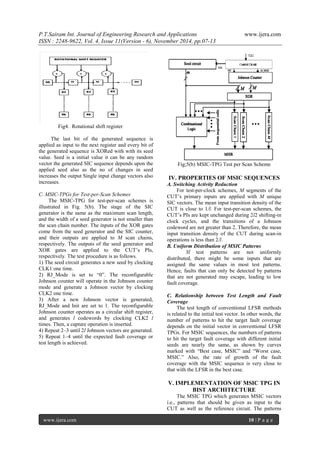
Fig 8. MSIC TPG Patterns VIII. CONCLUSION This paper has proposed a low-power test pattern generation method that could be easily implemented by hardware. It also developed a theory to express a sequence generated by linear sequential architectures, and extracted a class of SIC sequences named MSIC. Analysis results showed that an MSIC sequence had the favorable features of uniform distribution, low input transition density, and low dependency relationship between the test length and the TPG’s initial states. Combined with the proposed reconfigurable Johnson counter or scalable SIC counter, the MSIC-TPG can be easily implemented, and is flexible to test-per-clock schemes and test- per-scan schemes. For a test-per-clock scheme, the MSIC-TPG applies SIC sequences to the CUT with the SRAM-like grid. For a test-per scan scheme, the MSIC-TPG converts an SIC vector to low transition vectors for all scan chains. Experimental results and analysis results demonstrate that the MSIC-TPG is scalable to scan length, and has negligible impact on the test overhead. REFERENCES [1] Y. Zorian, “A distributed BIST control scheme for complex VLSI devices,” in 11th Annu. IEEE VLSI Test Symp. Dig. Papers, Apr. 1993, pp. 4–9. [2] P. Girard, “Survey of low-power testing of VLSI circuits,” IEEE DesignTest Comput., vol. 19, no. 3, pp. 80–90, May–Jun. 2002. [3] A. Abu-Issa and S. Quigley, “Bit-swapping LFSR and scan-chain ordering: A novel technique for peak- and average-power reduction in scan-based BIST,” IEEE Trans. Comput.-Aided Design Integr. Circuit Syst., vol. 28, no. 5, pp. 755–759, May 2009.
[4] P. Girard, L. Guiller, C. Landrault, S. Pravossoudovitch, J. Figueras, S. Manich, P. Teixeira, and M. Santos, “Low-energy BIST design: Impact of the LFSR TPG parameters on the weighted switching activity,” in Proc. IEEE Int. Symp. Circuits Syst., vol. 1. Jul. 1999, pp. 110–113. [5] S. Wang and S. Gupta, “DS-LFSR: A BIST TPG for low switching activity,” IEEE Trans. Comput.-Aided Design Integr. Circuits Syst., vol. 21, no. 7, pp. 842–851, Jul. 2002. [6] F. Corno, M. Rebaudengo, M. Reorda, G. Squillero, and M. Violante, Low power BIST via non-linear hybrid cellular automata,” in Proc. 18th IEEE VLSI Test Symp., Apr.–May 2000, pp. 29–34. [7] P. Girard, L. Guiller, C. Landrault, S. Pravossoudovitch, and H. Wunderlich, “A modified clock scheme for a low power BIST test pattern generator,” in Proc. 19th IEEE VTS VLSI Test Symp., Mar.–Apr. 2001, pp. 306–311. [8] D. Gizopoulos, N. Krantitis, A. Paschalis, M. Psarakis, and Y. Zorian, “Low power/energy BIST scheme for datapaths,” in Proc. 18th IEEE VLSI Test Symp., Apr.– May 2000, pp. 23–28. [9] Y. Bonhomme, P. Girard, L. Guiller, C. Landrault, and S. Pravossoudovitch, “A gated clock scheme for low power scan testing of logic ICs or embedded cores,” in Proc. 10th Asian Test Symp., Nov. 2001, pp. 253–258. [10] C. Laoudias and D. Nikolos, “A new test pattern generator for high defect coverage in a BIST environment,” in Proc. 14th ACM Great Lakes Symp. VLSI, Apr. 2004, pp. 417–420. [11] S. Bhunia, H. Mahmoodi, D. Ghosh, S. Mukhopadhyay, and K. Roy, “Low-power scan design using first-level supply gating,” IEEE Trans. Very Large Scale Integr. (VLSI) Syst., vol. 13, no. 3, pp. 384–395, Mar. 2005. [12] X. Kavousianos, D. Bakalis, and D. Nikolos, “Efficient partial scan cell gating for low- power scan-based testing,” ACM Trans. Design Autom. Electron. Syst., vol. 14, no. 2, pp. 28-1–28-15, Mar. 2009. [13] P. Girard, L. Guiller, C. Landrault, and S. Pravossoudovitch, “A test vector inhibiting technique for low energy BIST design,” in Proc. 17th IEEE VLSI Test Symp., Apr. 1999, pp. 407–412.
[14] S. Manich, A. Gabarro, M. Lopez, J. Figueras, P. Girard, L. Guiller, C. Landrault, S. Pravossoudovitch, P. Teixeira, and M. Santos, “Low power BIST by filtering non-](https://image.slidesharecdn.com/b0411060713-141212224649-conversion-gate01/85/Reduced-Test-Pattern-Generation-of-Multiple-SIC-Vectors-with-Input-and-Output-Delay-Faults-6-320.jpg)
![P.T.Sairam Int. Journal of Engineering Research and Applications www.ijera.com
ISSN : 2248-9622, Vol. 4, Issue 11(Version - 6), November 2014, pp.07-13
www.ijera.com 13 | P a g e
detecting vectors,” J. Electron. Test.-Theory Appl., vol. 16, no. 3, pp. 193–202, Jun. 2000. [15] F. Corno, M. Rebaudengo, M. Reorda, and M. Violante, “A new BIST architecture for low power circuits,” in Proc. Eur. Test Workshop, May 1999, pp. 160–164. [16] S. Gerstendorfer and H.-J. Wunderlich, “Minimized power consumption for scan- based BIST,” in Proc. Int. Test Conf., Sep. 1999, pp. 77–84. [17] A. Hertwing and H. Wunderlich, “Low power serial built-in self-test,” in Proc. Eur. Test Workshop, 1998, pp. 49–53. [18] S. Wang and W. Wei, “A technique to reduce peak current and average power dissipation in scan designs by limited capture,” in Proc. Asia South Pacific Design Autom. Conf., Jan. 2007, pp. 810–816. [19] N. Basturkmen, S. Reddy, and I. Pomeranz, “A low power pseudorandom BIST technique,” in Proc. IEEE Int. Conf. Comput. Design: VLSI Comput. Process., Sep. 2002, pp. 468–473. [20] S. Wang and S. Gupta, “LT-RTPG: A new test-per-scan BIST TPG for low switching activity,” IEEE Trans. Comput.-Aided Design Integr. Circuits Syst., vol. 25, no. 8, pp. 1565–1574, Aug. 2006. [21] M. Nourani, M. Tehranipoor, and N. Ahmed, “Low-transition test pattern generation for BIST-based applications,” IEEE Trans. Comput., vol. 57, no. 3, pp. 303–315, Mar. 2008. [22] X. Zhang, K. Roy, and S. Bhawmik, “POWERTEST: A tool for energy conscious weighted random pattern testing,” in Proc. 12th Int. Conf. VLSI Design, Jan. 1999, pp. 416–422. [23] S. F. Q. Abdallatif and S. Abu-Issa, “Multi- degree smoother for low power consumption in single and multiple scan-chains BIST,” in Proc. 11th Int. Symp. Qual. Electron. Design, Apr. 2010, pp. 689–696. [24] S. Chun, T. Kim, and S. Kang, “A new low energy BIST using a statistical code,” in Proc. Asia South Pacific Design Autom. Conf., Mar. 2008, pp. 647–652. [25] B. Zhou, Y.-Z. Ye, Z.-L. Li, X.-C. Wu, and R. Ke, “A new low power test pattern generator using a variable-length ring counter,” in Proc. Qual. Electron. Design, Mar. 2009, pp. 248–252. [26] Test Patterns of Multiple SIC Vectors: Theory and Application in BIST Schemes Feng Liang, Luwen Zhang, Shaochong Lei, Guohe Zhang, Kaile Gao, and Bin Liang](https://image.slidesharecdn.com/b0411060713-141212224649-conversion-gate01/85/Reduced-Test-Pattern-Generation-of-Multiple-SIC-Vectors-with-Input-and-Output-Delay-Faults-7-320.jpg)

This paper discusses a new method for generating test patterns in VLSI circuits, focusing on reducing power consumption during test mode operations. The proposed approach employs multiple single-input change (MSIC) sequences to minimize input transitions and enhance the uniformity of test patterns, offering advantages such as reduced hardware overhead and improved fault coverage. The study evaluates the effectiveness of this approach within a built-in self-test (BIST) architecture, illustrating its potential to streamline VLSI testing processes.