Downloaded 402 times


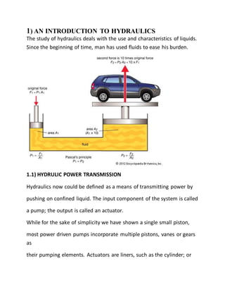


![[A] TERMINOLOGY OF PUNCHING MACHINE
Introduction: Punching machine type of cold working process in which
punching done by the punch machine tool and die designed to hole the
sheet metal by applying mechanical force or pressure. The punch
governs the size of the hole and the clearance is provided on the die.
(1) Punch: It is the male member of the unit and kept as small as
possible consistent with required strength and rigidity. The punch made
of the hard, wear resistance metal and is finally ground to the pre-
determine size providing just opium clearance between the punch and
die.
(2) Punch retainer of punch plate: It fits closely over the body of the
punch and holds it in a proper relative position. The retainer is turn to
bolt to the punch holder.
(3) Punch holder: It provided a wide plate surface which face against
the lower end of the press ram and is anchored to it with help of the
shank which is an integral part of the punch holder shank exactly fits in
to the ram opening, to help in properly positioning and aligning the
punch holder is made of cast steel.
(4)Backing plate: Whenever the punch is headless a hardness steel
backing plate is introduced between the back of the punch holder so
that intensity of pressure does not become excessive on the punch
holder. Backing plate distribute the pressure over wide area and
intensity of the pressure on the punch holder is reduced to avoid
crushing.
5) Die Block: it is female working member & is kept as small as possible
consistent with required strength. It is also made of hard, wear-](https://image.slidesharecdn.com/reportmain-161103142023/85/Hydraulic-punching-machine-project-report-26-320.jpg)


![[B] SHEARING ACTION IN DIE CUTTING OPERATION: In die
cutting operation the sheet metal stressed in shear between two
cutting edges to the point of fracture beyond it ultimate strength. In die
cutting operation when the punch presses at various places as shown in
fig. layer below the punch are subjected to different type of stresses at
various placed shown in fig. layer below the punch are subjected to
compressive stressed and the bottom most layer of the sheet die are
subjected to tensile stresses, this leads to stretching beyond the elastic
limit. Further moment of punch leads to plastic deformation, reduction
in area and finally fracture start through cleavage planes in a reduced
area.
THE VARIOUS STEPS IN SHERING ARE AS BELOW:
a) Plastic deformation: The pressure is applied by the punch on the
sheet metal tends to deform it in to die opening. As the elastic limit
exceeded by further loading a portion of the metal is forced in to the
die opening in the form of an embossed pad on the lower face of
material and corresponding depression on the upper face.
b) Reduction in thickness: As the load is further increased, the punch
penetrates the metal to certain depth and force and equal portion of
metal thickness in the die. This penetrates occurs before factoring
starts and reduced the cross-section area of metal through which is cut
being made.
c) Fracture: After above stage, fracture will start in the reduced area n
both upper and lower cutting edges and if the die and punch is suitable
for the material being cut, these fracture will spread out to word each
other and eventually meet, causing complete separation. Thus the](https://image.slidesharecdn.com/reportmain-161103142023/85/Hydraulic-punching-machine-project-report-29-320.jpg)
![punch penetrates the metal causing plastic deformation it then shears
it and pushes the cut piece from the sheet.
[C] SELECTING THE PROPER PRESS: In the selection of proper
size and style of press for a given kind of work the following points are
to be considered.
1. The size and type of die required.
2. The length of stroke necessary.
3. The pressure for doing the work.
4. The distance above the bottom of the stroke where the pressure
first occurs.
5. Any additional pressure required due to the attachment such as the
blank holder, ironing wrinkles or stretching the material in drawing
work.
6. The method of feeding, the direction of feed and the size of sheet
blank or work piece.](https://image.slidesharecdn.com/reportmain-161103142023/85/Hydraulic-punching-machine-project-report-30-320.jpg)
![[D] CLEARANCE: The die opening must be sufficiently larger than
the punch to permit and clean fracture of the metal. This different is
dimensions between the mating members or a die set are called
“clearance”. This clearance is applied in the following manners. When
the holes has to be held to size, i.e., the hole in the sheet metal is to be
accurate, and slug is to be discarded, the punch is made to the size of
hole and to a die opening size is obtained by adding clearance to the
punch size. C is the amount of clearance per size of the die opening.
The clearance is function of the kind, thickness and temper of the work
material requiring larger clearance than soft material. The exception
being aluminum. The usual clearances per side of the die, for various
metals, are giving below in terms of the stock thickness, t:
For brass and soft steel, C=5% of t
For medium steel, C=6% of t
For hard steel, C=7%of t
For Aluminum, C=10%of t
The total clearance between punch and die size will be this figure.
These clearances may be determined with the help of the following
relation:
C=0.0032 t (Ts), mm
Where T0 is the shear strength of the material in N/mm2](https://image.slidesharecdn.com/reportmain-161103142023/85/Hydraulic-punching-machine-project-report-31-320.jpg)
![[E] DIE: The die may be defined as the female part of complete tool
for producing work in press. It also referred to a complete tool
consisting of a pan of mating members for producing work in press.
TYPES OF DIES:
This die may be classified according to the type of press operation and
according to the method of operation.
Type of press operation: according to this to this criterion, the dies may
be classified as: cutting dies and forming dies.
Cutting dies: These dies are used to cut the metal they utilize the
cutting or shearing action. The common cutting dies are: blanking dies,
piercing dies, perforating dies, notching trimming, saving and nibbling
dies etc.
Method of operation: according to this criterion, the dies may be
classified as: single operation or simple dies, compound dies,
combination dies, progressive dies, transfer dies, and multiple dies.
Simple dies: simple dies or single action dies perform single operation
for each stroke of the press slide the operation may be any of the
opration listed under cutting or forming dies.](https://image.slidesharecdn.com/reportmain-161103142023/85/Hydraulic-punching-machine-project-report-32-320.jpg)
![[F] PUNCH:
This is the male component of the die assembly. This is directly or
indirectly moved by and fastened to the press ram or slide.
Method of mounting punches:
Headless punches
Peen head punches
Quelled punches
Larger punches are provided with heads or shoulders
Thin rectangular punches
Peen head punches Punches
less than 20mm diameter are often made from 20mm or smaller
diameter rod and are left shoulder less until assembly when the punch
pressed tightly in to a counter sunk reamed hole in the punch plate an
the riveted our the shank of the port blow of the punch placed in the
punch plate is always made circular and larger than the piercing section
in older to facilitate assembly to 5mm and 3mm for punch dimension
up to 10mm and 4mm for dimension up to 15mm.
This type of construction on the punch head is widely used on
perforating operation where a great many small and closely spaced
whole must be pierced slender punches for perforating further
supported and guided by making then sliding fit in the stripper plate.](https://image.slidesharecdn.com/reportmain-161103142023/85/Hydraulic-punching-machine-project-report-33-320.jpg)


This document is a project report submitted by 6 students for their Bachelor of Engineering degree. It describes the design and fabrication of a hydraulic sheet metal punching machine using leverage principles. The report contains 4 chapters that introduce hydraulics systems and components, describe punching machines, present the design of the machine parts, and include drawings of the machine assembly. It was guided by a professor and submitted to fulfill degree requirements.


