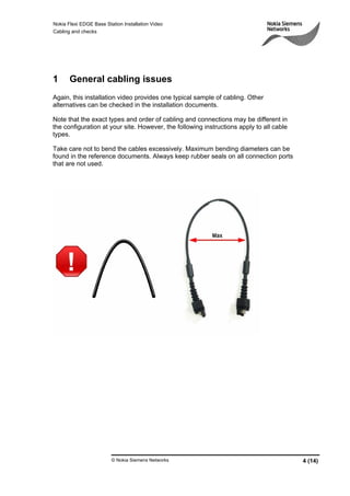
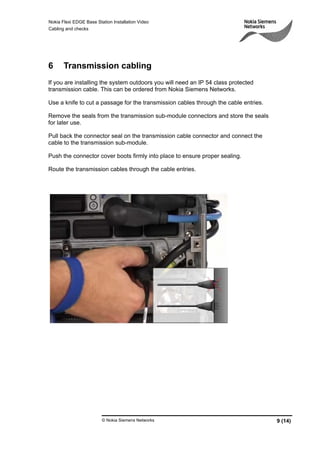
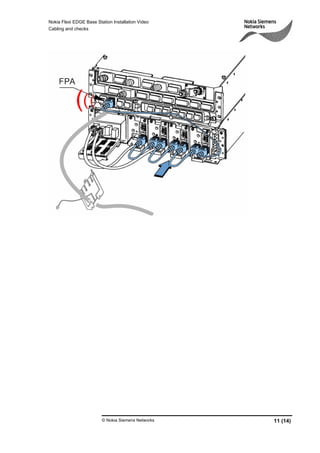
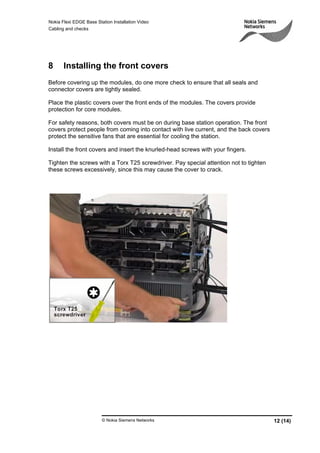
© Nokia Siemens Networks 1 (14)
Nokia Flexi EDGE Base Station
Installation Video
-
Cabling and checks
Nokia Flexi EDGE Base Station Installation Video
Cabling and checks
© Nokia Siemens Networks 2 (14)
Legal notice
Intellectual Property Rights
All copyrights and intellectual property rights for Nokia Siemens Networks training
documentation, product documentation and slide presentation material, all of which
are forthwith known as Nokia Siemens Networks training material, are the exclusive
property of Nokia Siemens Networks. Nokia Siemens Networks owns the rights to
copying, modification, translation, adaptation or derivatives including any
improvements or developments. Nokia Siemens Networks has the sole right to
copy, distribute, amend, modify, develop, license, sublicense, sell, transfer and
assign the Nokia Siemens Networks training material. Individuals can use the Nokia
Siemens Networks training material for their own personal self-development only,
those same individuals cannot subsequently pass on that same Intellectual Property
to others without the prior written agreement of Nokia Siemens Networks. The
Nokia Siemens Networks training material cannot be used outside of an agreed
Nokia Siemens Networks training session for development of groups without the
prior written agreement of Nokia Siemens Networks.
Indemnity
The information in this document is subject to change without notice and describes
only the product defined in the introduction of this documentation. This document is
intended for the use of Nokia Siemens Networks customers only for the purposes of
the agreement under which the document is submitted, and no part of it may be
used, reproduced, modified or transmitted in any form or means without the prior
written permission of Nokia Siemens Networks. The document has been prepared
to be used by professional and properly trained personnel, and the customer
assumes full responsibility when using it. Nokia Siemens Networks welcomes
customer comments as part of the process of continuous development and
improvement of the documentation.
The information or statements given in this document concerning the suitability,
capacity, or performance of the mentioned hardware or software products are given
“as is” and all liability arising in connection with such hardware or software products
shall be defined conclusively in a separate agreement between Nokia Siemens
Networks and the customer. However, Nokia Siemens Networks has made all
reasonable efforts to ensure that the instructions contained in the document are
adequate and free of material errors and omissions. Nokia Siemens Networks will, if
deemed necessary by Nokia Siemens Networks, explain issues which may not be
covered by the document.
Nokia Siemens Networks will correct errors in the document as soon as possible. IN
NO EVENT WILL NOKIA SIEMENS NETWORKS BE LIABLE FOR ERRORS IN
THIS DOCUMENT OR FOR ANY DAMAGES, INCLUDING BUT NOT LIMITED TO
SPECIAL, DIRECT, INDIRECT, INCIDENTAL OR CONSEQUENTIAL OR ANY
MONETARY LOSSES,SUCH AS BUT NOT LIMITED TO LOSS OF PROFIT,
REVENUE, BUSINESS INTERRUPTION, BUSINESS OPPORTUNITY OR
DATA,THAT MAY ARISE FROM THE USE OF THIS DOCUMENT OR THE
INFORMATION IN IT
This document and the product it describes are considered protected by copyrights
and other intellectual property rights according to the applicable laws.
Wave logo is a trademark of Nokia Siemens Networks Oy. Nokia is a registered
trademark of Nokia Corporation. Siemens is a registered trademark of Siemens
AG.
Other product names mentioned in this document may be trademarks of their
respective owners, and they are mentioned for identification purposes only.
Copyright © Nokia Siemens Networks 2007. All rights reserved.
Nokia Flexi EDGE Base Station Installation Video
Cabling and checks
© Nokia Siemens Networks 3 (14)
Table of Contents:
1 General cabling issues.........................................................................................4
2 Internal bus cabling ..............................................................................................5
3 Internal power cabling ..........................................................................................6
4 RF cabling ............................................................................................................7
5 Antenna jumper cabling........................................................................................8
6 Transmission cabling............................................................................................9
7 Optional alarm cables.........................................................................................10
8 Installing the front covers ...................................................................................12
9 External cable tying............................................................................................13
10 Checking the installation ................................................................................14
Nokia Flexi EDGE Base Station Installation Video
Cabling and checks
© Nokia Siemens Networks 4 (14)
1 General cabling issues
Again, this installation video provides one typical sample of cabling. Other
alternatives can be checked in the installation documents.
Note that the exact types and order of cabling and connections may be different in
the configuration at your site. However, the following instructions apply to all cable
types.
Take care not to bend the cables excessively. Maximum bending diameters can be
found in the reference documents. Always keep rubber seals on all connection ports
that are not used.
Nokia Flexi EDGE Base Station Installation Video
Cabling and checks
© Nokia Siemens Networks 5 (14)
2 Internal bus cabling
The bus cables are connected between the System Module (ESMA) and each of the
Dual TRX (EXxA) Modules.
Exact connection ports vary according to the configuration. Check the correct ports
from the ’Hardware Configuration Reference Guide’ document.
Never loop bus cables back to the module where the cables originate, since this may
cause unexpected false functioning.
Pull back the connector seals and connect the cables between the System Module
and the Dual TRX Modules’ bus connectors. Route the cables through the external
side cable entry slots.
Make sure that all the connector seals are properly in place. Tie loose cabling with
cable clamps to the side of the casings.
Nokia Flexi EDGE Base Station Installation Video
Cabling and checks
© Nokia Siemens Networks 6 (14)
3 Internal power cabling
The internal power cables are used to distribute power to the Dual TRX Modules.
They connect the System Module (ESMA) to each of the Dual TRX Modules (EXxA)
separately.
Exact connection ports vary according to the configuration. Check the correct ports
from the ’Hardware Configuration Reference Guide’ document.
Pull back on the connector seals to uncover the connectors.
Connect the cables to the System Module and one cable to each Dual TRX Module.
Next connect the power cables between the Dual TRX and Dual Duplexer modules.
Push all the connector seals firmly into place.
Route the cables through the lower holes of the external cable entries.
Nokia Flexi EDGE Base Station Installation Video
Cabling and checks
© Nokia Siemens Networks 7 (14)
4 RF cabling
As with all cables, pay special attention to connect the correct cables to their correct
connectors. Connecting TX cables to RX connectors will cause damage to the
modules.
Remove the sealing caps from the RF connectors that you intend to use. These caps
are sealed tight for weather protection. You may need to pull the caps off with pliers
but do so carefully and only pull directly away from the base station to avoid
damaging the connectors.
The image and the codings on screen show the correct RF connections. Note that
there are colour codings in the ports to help the identification.
Connect the TxA and TxB cables to their respective counterparts.
Connect RxA1 port to RxA, and RxB1 to RxB port. See that the pre-installed RXAO-
RXAI cable is properly in place.
Push the seals firmly over the connectors to prevent moisture from leaking in.
Nokia Flexi EDGE Base Station Installation Video
Cabling and checks
© Nokia Siemens Networks 8 (14)
5 Antenna jumper cabling
Antenna cables connect to the antenna connectors in the front panels of the Dual
Duplexer (ERxA) Modules. The number of cables used depends on the configuration.
Cut through the cable entry rubber seals. Remove the seals from the antenna
connectors in the Dual Duplexer Modules or Remote tune Combiner Modules. It is
important to save the seals for later use during maintenance operations.
Route the antenna jumper cables through the cuts and connect them to the modules.
Tighten the connectors with a torque wrench set to 25 Nm.
Repeat the steps above for all necessary modules in your configuration.
Nokia Flexi EDGE Base Station Installation Video
Cabling and checks
© Nokia Siemens Networks 9 (14)
6 Transmission cabling
If you are installing the system outdoors you will need an IP 54 class protected
transmission cable. This can be ordered from Nokia Siemens Networks.
Use a knife to cut a passage for the transmission cables through the cable entries.
Remove the seals from the transmission sub-module connectors and store the seals
for later use.
Pull back the connector seal on the transmission cable connector and connect the
cable to the transmission sub-module.
Push the connector cover boots firmly into place to ensure proper sealing.
Route the transmission cables through the cable entries.
Nokia Flexi EDGE Base Station Installation Video
Cabling and checks
© Nokia Siemens Networks 10 (14)
7 Optional alarm cables
If present in your configuration, the optional power module holds between one to four
sub-modules that are all either AC/DC sub-modules (FPAA) or battery sub-modules
(FPBA).
The sub modules have RJ-45 ports in their front panels for chaining them together
from left to right as shown on screen. Finally the rightmost sub-module is connected
to the FPA port of the System Module after routing the cable through the cable
entries.
These connections form a chain of alarms that alert for maintenance needs such as
cooling fan failures or overheating. In AC/DC submodules, alerts can also be caused
by abnormalities in the AC input voltage.
Another set of alarms is relayed by the optional External Alarms and Controls (EAC)
cable.
The end user can define these alarms during the commissioning process. Examples
of these include smoke detection or a cabinet open door alarm.
Note that when you connect the EAC cable in an outdoor wall or pole installation, the
cables should be routed via the lower cable entry slot whenever possible.
Remove the connector seal from the EAC connector in the System Module front
panel and store the seal for later use. Connect the EAC cable to the connector and
route the cable through the cable entry.
Attach the other end of the cable to the external alarms control box as shown on
screen.
The cable can also be attached to an UltraSite/ExtraTalk alarm cable or an alarm
distribution frame.
Nokia Flexi EDGE Base Station Installation Video
Cabling and checks
© Nokia Siemens Networks 11 (14)
Nokia Flexi EDGE Base Station Installation Video
Cabling and checks
© Nokia Siemens Networks 12 (14)
8 Installing the front covers
Before covering up the modules, do one more check to ensure that all seals and
connector covers are tightly sealed.
Place the plastic covers over the front ends of the modules. The covers provide
protection for core modules.
For safety reasons, both covers must be on during base station operation. The front
covers protect people from coming into contact with live current, and the back covers
protect the sensitive fans that are essential for cooling the station.
Install the front covers and insert the knurled-head screws with your fingers.
Tighten the screws with a Torx T25 screwdriver. Pay special attention not to tighten
these screws excessively, since this may cause the cover to crack.
Nokia Flexi EDGE Base Station Installation Video
Cabling and checks
© Nokia Siemens Networks 13 (14)
9 External cable tying
A complete Flexi EDGE BTS installation will have a variety of different cables
emerging from the system.
Loose cables are easily caught on moving objects and people, and should therefore
be tied up in bundles and secured out of the way.
Do not bend the cables sharply, and do not pull on them in such a way that you could
cause connections inside to come loose.
Bundle the cables together and fasten them with cable ties to fixed structures so that
there is no danger of tripping over them.
In areas of direct sunlight, cable ties will degrade rapidly due to ultraviolet radiation.
In these cases it is better to use cable clamps instead.
Nokia Flexi EDGE Base Station Installation Video
Cabling and checks
© Nokia Siemens Networks 14 (14)
10 Checking the installation
Before leaving the site, confirm that you have checked all the boxes in the installation
checklist.
Clean up the site for the safety and comfort of the next visitors. Recycle all materials
according to instructions.
In the final section of this e-Learning course, you will find several helpful documents
that provide additional information on the Flexi EDGE BTS product and installation
and maintenance procedures.

Nokia FLexi Edge BTS Installation Cabling and Checks

  • 1.
    © Nokia SiemensNetworks 1 (14) Nokia Flexi EDGE Base Station Installation Video - Cabling and checks
  • 2.
    Nokia Flexi EDGEBase Station Installation Video Cabling and checks © Nokia Siemens Networks 2 (14) Legal notice Intellectual Property Rights All copyrights and intellectual property rights for Nokia Siemens Networks training documentation, product documentation and slide presentation material, all of which are forthwith known as Nokia Siemens Networks training material, are the exclusive property of Nokia Siemens Networks. Nokia Siemens Networks owns the rights to copying, modification, translation, adaptation or derivatives including any improvements or developments. Nokia Siemens Networks has the sole right to copy, distribute, amend, modify, develop, license, sublicense, sell, transfer and assign the Nokia Siemens Networks training material. Individuals can use the Nokia Siemens Networks training material for their own personal self-development only, those same individuals cannot subsequently pass on that same Intellectual Property to others without the prior written agreement of Nokia Siemens Networks. The Nokia Siemens Networks training material cannot be used outside of an agreed Nokia Siemens Networks training session for development of groups without the prior written agreement of Nokia Siemens Networks. Indemnity The information in this document is subject to change without notice and describes only the product defined in the introduction of this documentation. This document is intended for the use of Nokia Siemens Networks customers only for the purposes of the agreement under which the document is submitted, and no part of it may be used, reproduced, modified or transmitted in any form or means without the prior written permission of Nokia Siemens Networks. The document has been prepared to be used by professional and properly trained personnel, and the customer assumes full responsibility when using it. Nokia Siemens Networks welcomes customer comments as part of the process of continuous development and improvement of the documentation. The information or statements given in this document concerning the suitability, capacity, or performance of the mentioned hardware or software products are given “as is” and all liability arising in connection with such hardware or software products shall be defined conclusively in a separate agreement between Nokia Siemens Networks and the customer. However, Nokia Siemens Networks has made all reasonable efforts to ensure that the instructions contained in the document are adequate and free of material errors and omissions. Nokia Siemens Networks will, if deemed necessary by Nokia Siemens Networks, explain issues which may not be covered by the document. Nokia Siemens Networks will correct errors in the document as soon as possible. IN NO EVENT WILL NOKIA SIEMENS NETWORKS BE LIABLE FOR ERRORS IN THIS DOCUMENT OR FOR ANY DAMAGES, INCLUDING BUT NOT LIMITED TO SPECIAL, DIRECT, INDIRECT, INCIDENTAL OR CONSEQUENTIAL OR ANY MONETARY LOSSES,SUCH AS BUT NOT LIMITED TO LOSS OF PROFIT, REVENUE, BUSINESS INTERRUPTION, BUSINESS OPPORTUNITY OR DATA,THAT MAY ARISE FROM THE USE OF THIS DOCUMENT OR THE INFORMATION IN IT This document and the product it describes are considered protected by copyrights and other intellectual property rights according to the applicable laws. Wave logo is a trademark of Nokia Siemens Networks Oy. Nokia is a registered trademark of Nokia Corporation. Siemens is a registered trademark of Siemens AG. Other product names mentioned in this document may be trademarks of their respective owners, and they are mentioned for identification purposes only. Copyright © Nokia Siemens Networks 2007. All rights reserved.
  • 3.
    Nokia Flexi EDGEBase Station Installation Video Cabling and checks © Nokia Siemens Networks 3 (14) Table of Contents: 1 General cabling issues.........................................................................................4 2 Internal bus cabling ..............................................................................................5 3 Internal power cabling ..........................................................................................6 4 RF cabling ............................................................................................................7 5 Antenna jumper cabling........................................................................................8 6 Transmission cabling............................................................................................9 7 Optional alarm cables.........................................................................................10 8 Installing the front covers ...................................................................................12 9 External cable tying............................................................................................13 10 Checking the installation ................................................................................14
  • 4.
    Nokia Flexi EDGEBase Station Installation Video Cabling and checks © Nokia Siemens Networks 4 (14) 1 General cabling issues Again, this installation video provides one typical sample of cabling. Other alternatives can be checked in the installation documents. Note that the exact types and order of cabling and connections may be different in the configuration at your site. However, the following instructions apply to all cable types. Take care not to bend the cables excessively. Maximum bending diameters can be found in the reference documents. Always keep rubber seals on all connection ports that are not used.
  • 5.
    Nokia Flexi EDGEBase Station Installation Video Cabling and checks © Nokia Siemens Networks 5 (14) 2 Internal bus cabling The bus cables are connected between the System Module (ESMA) and each of the Dual TRX (EXxA) Modules. Exact connection ports vary according to the configuration. Check the correct ports from the ’Hardware Configuration Reference Guide’ document. Never loop bus cables back to the module where the cables originate, since this may cause unexpected false functioning. Pull back the connector seals and connect the cables between the System Module and the Dual TRX Modules’ bus connectors. Route the cables through the external side cable entry slots. Make sure that all the connector seals are properly in place. Tie loose cabling with cable clamps to the side of the casings.
  • 6.
    Nokia Flexi EDGEBase Station Installation Video Cabling and checks © Nokia Siemens Networks 6 (14) 3 Internal power cabling The internal power cables are used to distribute power to the Dual TRX Modules. They connect the System Module (ESMA) to each of the Dual TRX Modules (EXxA) separately. Exact connection ports vary according to the configuration. Check the correct ports from the ’Hardware Configuration Reference Guide’ document. Pull back on the connector seals to uncover the connectors. Connect the cables to the System Module and one cable to each Dual TRX Module. Next connect the power cables between the Dual TRX and Dual Duplexer modules. Push all the connector seals firmly into place. Route the cables through the lower holes of the external cable entries.
  • 7.
    Nokia Flexi EDGEBase Station Installation Video Cabling and checks © Nokia Siemens Networks 7 (14) 4 RF cabling As with all cables, pay special attention to connect the correct cables to their correct connectors. Connecting TX cables to RX connectors will cause damage to the modules. Remove the sealing caps from the RF connectors that you intend to use. These caps are sealed tight for weather protection. You may need to pull the caps off with pliers but do so carefully and only pull directly away from the base station to avoid damaging the connectors. The image and the codings on screen show the correct RF connections. Note that there are colour codings in the ports to help the identification. Connect the TxA and TxB cables to their respective counterparts. Connect RxA1 port to RxA, and RxB1 to RxB port. See that the pre-installed RXAO- RXAI cable is properly in place. Push the seals firmly over the connectors to prevent moisture from leaking in.
  • 8.
    Nokia Flexi EDGEBase Station Installation Video Cabling and checks © Nokia Siemens Networks 8 (14) 5 Antenna jumper cabling Antenna cables connect to the antenna connectors in the front panels of the Dual Duplexer (ERxA) Modules. The number of cables used depends on the configuration. Cut through the cable entry rubber seals. Remove the seals from the antenna connectors in the Dual Duplexer Modules or Remote tune Combiner Modules. It is important to save the seals for later use during maintenance operations. Route the antenna jumper cables through the cuts and connect them to the modules. Tighten the connectors with a torque wrench set to 25 Nm. Repeat the steps above for all necessary modules in your configuration.
  • 9.
    Nokia Flexi EDGEBase Station Installation Video Cabling and checks © Nokia Siemens Networks 9 (14) 6 Transmission cabling If you are installing the system outdoors you will need an IP 54 class protected transmission cable. This can be ordered from Nokia Siemens Networks. Use a knife to cut a passage for the transmission cables through the cable entries. Remove the seals from the transmission sub-module connectors and store the seals for later use. Pull back the connector seal on the transmission cable connector and connect the cable to the transmission sub-module. Push the connector cover boots firmly into place to ensure proper sealing. Route the transmission cables through the cable entries.
  • 10.
    Nokia Flexi EDGEBase Station Installation Video Cabling and checks © Nokia Siemens Networks 10 (14) 7 Optional alarm cables If present in your configuration, the optional power module holds between one to four sub-modules that are all either AC/DC sub-modules (FPAA) or battery sub-modules (FPBA). The sub modules have RJ-45 ports in their front panels for chaining them together from left to right as shown on screen. Finally the rightmost sub-module is connected to the FPA port of the System Module after routing the cable through the cable entries. These connections form a chain of alarms that alert for maintenance needs such as cooling fan failures or overheating. In AC/DC submodules, alerts can also be caused by abnormalities in the AC input voltage. Another set of alarms is relayed by the optional External Alarms and Controls (EAC) cable. The end user can define these alarms during the commissioning process. Examples of these include smoke detection or a cabinet open door alarm. Note that when you connect the EAC cable in an outdoor wall or pole installation, the cables should be routed via the lower cable entry slot whenever possible. Remove the connector seal from the EAC connector in the System Module front panel and store the seal for later use. Connect the EAC cable to the connector and route the cable through the cable entry. Attach the other end of the cable to the external alarms control box as shown on screen. The cable can also be attached to an UltraSite/ExtraTalk alarm cable or an alarm distribution frame.
  • 11.
    Nokia Flexi EDGEBase Station Installation Video Cabling and checks © Nokia Siemens Networks 11 (14)
  • 12.
    Nokia Flexi EDGEBase Station Installation Video Cabling and checks © Nokia Siemens Networks 12 (14) 8 Installing the front covers Before covering up the modules, do one more check to ensure that all seals and connector covers are tightly sealed. Place the plastic covers over the front ends of the modules. The covers provide protection for core modules. For safety reasons, both covers must be on during base station operation. The front covers protect people from coming into contact with live current, and the back covers protect the sensitive fans that are essential for cooling the station. Install the front covers and insert the knurled-head screws with your fingers. Tighten the screws with a Torx T25 screwdriver. Pay special attention not to tighten these screws excessively, since this may cause the cover to crack.
  • 13.
    Nokia Flexi EDGEBase Station Installation Video Cabling and checks © Nokia Siemens Networks 13 (14) 9 External cable tying A complete Flexi EDGE BTS installation will have a variety of different cables emerging from the system. Loose cables are easily caught on moving objects and people, and should therefore be tied up in bundles and secured out of the way. Do not bend the cables sharply, and do not pull on them in such a way that you could cause connections inside to come loose. Bundle the cables together and fasten them with cable ties to fixed structures so that there is no danger of tripping over them. In areas of direct sunlight, cable ties will degrade rapidly due to ultraviolet radiation. In these cases it is better to use cable clamps instead.
  • 14.
    Nokia Flexi EDGEBase Station Installation Video Cabling and checks © Nokia Siemens Networks 14 (14) 10 Checking the installation Before leaving the site, confirm that you have checked all the boxes in the installation checklist. Clean up the site for the safety and comfort of the next visitors. Recycle all materials according to instructions. In the final section of this e-Learning course, you will find several helpful documents that provide additional information on the Flexi EDGE BTS product and installation and maintenance procedures.