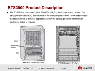
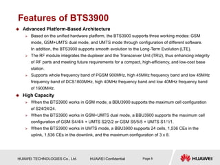
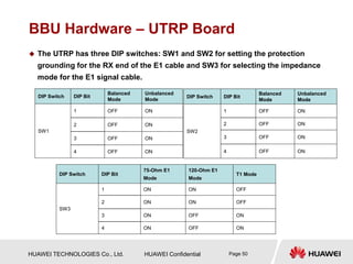
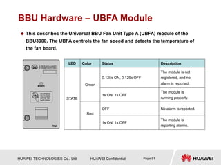
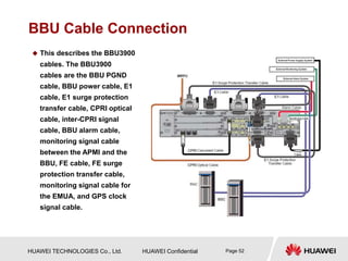
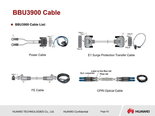
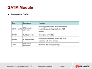
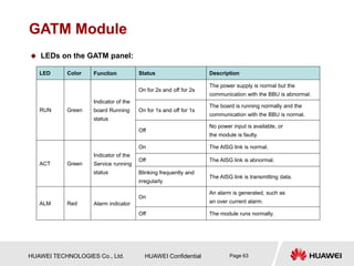
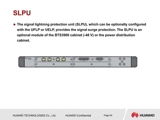
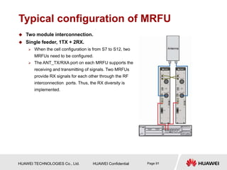
www.huawei.com
HUAWEI Confidential
Security Level: Internal Use
2009-02
HUAWEI BTS3900
Hardware Structure and Principle
ISSUE1.0
Wireless Case and Training
HUAWEI TECHNOLOGIES Co., Ltd. HUAWEI Confidential Page 2
 BTS3900 Base Station is the fourth generation base station
developed by Huawei. It features a multi-mode modular design
and supports three working modes: GSM mode, GSM+UMTS
dual mode, and UMTS mode through configuration of different
software. In addition, the BTS3900 supports smooth evolution
to the Long-Term Evolution (LTE).
HUAWEI TECHNOLOGIES Co., Ltd. HUAWEI Confidential Page 3
 Know the functions and features of BTS3900
 Master the hardware structure and function of BTS3900
 Master the typical configuration and RF Cable Connections
HUAWEI TECHNOLOGIES Co., Ltd. HUAWEI Confidential Page 4
 BTS3900 Hardware Description(V100R001_01)
 HUAWEI BTS3900&BTS3900A MRFU Deployment Guide
HUAWEI TECHNOLOGIES Co., Ltd. HUAWEI Confidential Page 5
Chapter 1 BTS3900 Product Description
Chapter 2 BTS3900 System Structure
HUAWEI TECHNOLOGIES Co., Ltd. HUAWEI Confidential Page 6
Location
PSTN
ISDN
PSPDN
Um Interface
BTS3900
BTS3900
BTS3900
BTS
OMC
HLR/AUC/EIR
BSC/RNC
MSC/VLR
SMC/VM
A/Iu Interface
MAP
TUP,ISUP
MS
MS
MS
MS: Mobile Station BTS: Base Transceiver Station BSC: Base Station Controller
HLR: Home Location Register AUC: Authentication Center RNC: Radio Network Controller
MSC: Mobile Switching Center VLR: Visitor Location Register SMC: Short Message Center
VM: Voice Mailbox EIR: Equipment Identity Register OMC: Operation and Maintenance Center
HUAWEI TECHNOLOGIES Co., Ltd. HUAWEI Confidential Page 7
BTS3900 Product Description
 The BTS3900 is comprised of the BBU3900, MRFU, and indoor macro cabinet. The
BBU3900 and the MRFU are installed in the indoor macro cabinet. The PS4890 meets
the requirements of different applications when the backup power or transmission
equipment space is required.
BTS3900 system structure PS4890 system structure
HUAWEI TECHNOLOGIES Co., Ltd. HUAWEI Confidential Page 8
Features of BTS3900
 Advanced Platform-Based Architecture
 Based on the unified hardware platform, the BTS3900 supports three working modes: GSM
mode, GSM+UMTS dual mode, and UMTS mode through configuration of different software.
In addition, the BTS3900 supports smooth evolution to the Long-Term Evolution (LTE).
 The RF module integrates the duplexer and the Transceiver Unit (TRU), thus enhancing integrity
of RF parts and meeting future requirements for a compact, high-efficiency, and low-cost base
station.
 Supports whole frequency band of PGSM 900MHz, high 45MHz frequency band and low 45MHz
frequency band of DCS1800MHz, high 40MHz frequency band and low 40MHz frequency band
of 1900MHz.
 High Capacity
 When the BTS3900 works in GSM mode, a BBU3900 supports the maximum cell configuration
of S24/24/24.
 When the BTS3900 works in GSM+UMTS dual mode, a BBU3900 supports the maximum cell
configuration of GSM S4/4/4 + UMTS S2/2/2 or GSM S5/5/5 + UMTS S1/1/1.
 When the BTS3900 works in UMTS mode, a BBU3900 supports 24 cells, 1,536 CEs in the
uplink, 1,536 CEs in the downlink, and the maximum configuration of 3 x 8.
HUAWEI TECHNOLOGIES Co., Ltd. HUAWEI Confidential Page 9
Features of BTS3900
 Transmission Sharing
 Sharing the CPRI port. The CPRI data of the GSM and UMTS networks can be multiplexed on the
same optical cable, which reduces the quantity of CPRI ports.
 Supports co-transmission between the GSM and the UMTS. Sharing transmission resources
between the Abis and the Iub interfaces.
 Flexible Clock Synchronization Modes
 Upper synchronization clock, extract clock from Abis/Iub interface.
 Extract clock from GPS (Global Positioning System).
 Synchronization with the IP clock, a highly cost-effective clock solution, which can be obtained
through software upgrade without additional hardware.
 Clock phase lock, tracing, and memory functions and free-run synchronization mode. When the
clock operates in free-run mode, the system can keep operational for at least 90 days at normal
temperature.
HUAWEI TECHNOLOGIES Co., Ltd. HUAWEI Confidential Page 10
Features of BTS3900
 Networking Capability
 The BTS3900 supports multiple network topologies, such as star, tree, chain, and ring
topologies.
 Supports Flex Abis networking.
 When working in UMTS mode, the BTS3900 supports ATM and IP dual stack to protect
operators' early investment in ATM transport.
 Supports optimized transmission on the Abis interface.
 Low Power Consumption
HUAWEI TECHNOLOGIES Co., Ltd. HUAWEI Confidential Page 11
Chapter 1 BTS3900 Product Description
Chapter 2 BTS3900 System Structure
HUAWEI TECHNOLOGIES Co., Ltd. HUAWEI Confidential Page 12
Abbreviation
Abbreviation Description
GTMU Transmission& Timing& Management Unit for BBU
WMPT WCDMA Main Processing and Transmission Unit
WBBPa WCDMA Baseband Process unit Type A
UTRP Universal Transmission Processing Unit
UPEA
Universal power and Environment interface unit
Type A (-48v)
BSBC Universal BBU Subrack Backplane Type C (2U)
UBFA Universal BBU Fan Unit Type A (2U)
UEIU Universal Environment Interface unit
UELP Universal E1/T1 Lighting Protection unit
UFLP Universal FE/GE Lighting Protection unit
CPRI Common Protocol Radio Interface
APM30H Advanced Power Module
HEUA The Heat Exchange Unit Type A
HPMI The Hert Power Monitoring Interface unit
HUAWEI TECHNOLOGIES Co., Ltd. HUAWEI Confidential Page 13
Sector 1 BTS3900 Cabinet
Sector 2 PS4890 Cabinet
Sector 3 BTS3900 Hardware Components
Sector 4 BTS3900 New Hardware
Sector 5 MRFU Working Mode
HUAWEI TECHNOLOGIES Co., Ltd. HUAWEI Confidential Page 14
Appearance of the BTS3900 Cabinet
 The BTS3900 cabinet is designed in compliance with the IEC297 standard. It is a
vertical cabinet.
HUAWEI TECHNOLOGIES Co., Ltd. HUAWEI Confidential Page 15
Hardware Structure of the BTS3900
Typical configuration of the BTS3900 cabinet (-48V)
 Hardware Structure of the BTS3900 (-48V)
 The BTS3900 cabinet (-48V) uses the external -48V DC input. The DC power is directly led
into the DCDU-01 and the DCDU-01 distributes the DC power to each component in the
cabinet.
 The BTS3900 cabinet (-48V) consists of the following components: the MRFUs, BBU,DCDU-
01, and FAN unit. You can optionally install devices of 3U in height in the spare space of the
cabinet.
HUAWEI TECHNOLOGIES Co., Ltd. HUAWEI Confidential Page 16
Hardware Structure of the BTS3900
 Hardware Structure of the BTS3900 (+24V)
 The BTS3900 cabinet (+24V) uses the external +24V DC input. The PSUs (DC/DC) convert
the external input power into -48V DC power and supply the -48V DC power to the DCDU-
01.Then, the DCDU-01 distributes the -48V DC power to each component in the cabinet.
 The BTS3900 cabinet (+24V) consists of the following components: the MRFUs, BBU, DCDU-
01, PSUs (DC/DC), and FAN unit.
Typical configuration of the BTS3900 cabinet (+24V)
HUAWEI TECHNOLOGIES Co., Ltd. HUAWEI Confidential Page 17
Hardware Structure of the BTS3900
 Hardware Structure of the BTS3900 (~220V)
 The BTS3900 cabinet (~220 V) uses the external 220 V AC input. The PSUs (AC/DC) convert
the external input power into -48 V DC power and supply the -48 V DC power to the DCDU-
01.Then, the DCDU-01 distributes the -48 V DC power to each component in the cabinet.
 The BTS3900 cabinet (~220 V) consists of the following components: the MRFUs,
BBU,DCDU-01, PMU, PSUs (AC/DC), and FAN unit.
Typical configuration of the BTS3900 cabinet (220 V)
HUAWEI TECHNOLOGIES Co., Ltd. HUAWEI Confidential Page 18
Sector 1 BTS3900 Cabinet
Sector 2 PS4890 Cabinet
Sector 3 BTS3900 Hardware Components
Sector 4 BTS3900 New Hardware
Sector 5 MRFU Working Mode
HUAWEI TECHNOLOGIES Co., Ltd. HUAWEI Confidential Page 19
Appearance of the PS4890 Cabinet
 The PS4890 cabinet is designed in compliance with the IEC297 standard. It is a
vertical cabinet.
HUAWEI TECHNOLOGIES Co., Ltd. HUAWEI Confidential Page 20
Hardware Structure of the PS4890
1、AC/DC power system 2、DCDU-04
3、DCDU-03
4、Copper bus bar for the negative
poles of the battery group
5、Battery support plate 6、Baffle plate
7、Copper busbar for the positive
poles of the battery group
 The PS4890 cabinet contains the power system and modules such as DCDU-04
and DCDU-03.
 The PS4890 cabinet configured with 48V 50 Ah, 48V 92 Ah, or 48V 184 Ah battery
groups provides the following functions:
 The power system converts the AC power into -48 V DC power and provides three outputs to
the battery groups, DCDU-04, and DCDU-03 through power distribution.
 The DCDU-04 provides two DC outputs to the BTS3900 cabinet or other primary BTSs.
 The DCDU-03 provides nine DC outputs to the transmission equipment.
HUAWEI TECHNOLOGIES Co., Ltd. HUAWEI Confidential Page 21
Installation of BTS3900 and PS4890 Together
Cable Number Cable Name Quantity
P1、P2 DCDU-04 output power cables 2
S1 Environment monitoring signal cable
between the PMU and the BBU
1
 Installation of BTS3900 and PS4890 in stack mode and side-by-side mode.
HUAWEI TECHNOLOGIES Co., Ltd. HUAWEI Confidential Page 22
Sector 1 BTS3900 Cabinet
Sector 2 PS4890 Cabinet
Sector 3 BTS3900 Hardware Components
Sector 4 BTS3900 New Hardware
Sector 5 MRFU Working Mode
HUAWEI TECHNOLOGIES Co., Ltd. HUAWEI Confidential Page 23
BTS3900 Components
 BTS3900 Hardware includes:
 BBU3900 Equipment
 MRFU (Multi carrier Radio Filter Unit)
 DCDU-01 (Direct Current Distribution Unit)
 FAN Unit
 GATM(GSM Antenna and TMA Control module)
 SLPU(Signal Lightning Protection Unit)
 PMU module
 PSU module (DC/DC)
 PSU module (AC/DC)
 Power subrack(DC/DC)
 Power subrack (AC/DC)
HUAWEI TECHNOLOGIES Co., Ltd. HUAWEI Confidential Page 24
BBU3900 Equipment
 The BBU3900, which features a case structure, can be installed in a 19-inch-wide
and 2U-high indoor space or outdoor protective cabinet.
 BBU3900 equipment includes:
 GTMU
 WMPT
 WBBP
 UTRP
 UPEU
 UEIU
 UELP
 UFLP
 UBFA
HUAWEI TECHNOLOGIES Co., Ltd. HUAWEI Confidential Page 25
Functions of the BBU3900
 As the baseband processing unit, the BBU3900 provides ports for connection
between the dual mode base station and the BSC/RNC and between the BBU3900
and the RF modules.
 The BBU3900 has the following functions:
 Provides ports for communication between the base station and the BSC/RNC.
 Provides CPRI ports for communication between the BBU and the RF modules.
 Provides USB ports, facilitating the automatic software upgrade of the dual-mode base station
when a USB disk is inserted during software installation and data configuration.
 Provides an OM channel between the base station and the LMT or the M2000 to operate and
maintain the base station.
 Processes uplink and downlink data.
 Manages the entire dual-mode system in terms of OM and signaling processing.
 Provides the system clock.
HUAWEI TECHNOLOGIES Co., Ltd. HUAWEI Confidential Page 26
BBU3900 Slots
 The slots of the BBU3900 GSM, BBU3900 GU, and BBU3900 UMTS are the same.
HUAWEI TECHNOLOGIES Co., Ltd. HUAWEI Confidential Page 27
Board configuration principles of the BBU3900 GSM
 BBU3900 GSM board includes: GTMU、UBFA、UPEU、UEIU、UELP.
Board
Name
Optional/
Mandatory
Maximum
Number
Slot Configuration
Limitations
GTMU Mandatory 1 Slot 5 and Slot 6 Only configured in slot 5 and slot 6
UBFA Mandatory 1 UBFA Only configured in the FAN slot
UPEU Mandatory 2 PWR1 or PWR2 Preferentially configured at the PWR2
slot in the case of a single UPEU
UEIU Optional 1 PWR1 ——
UELP Mandatory 2 Slot 0 or Slot 4 In the case of less than or equal to four E1s, one UELP is
required and installed in slot 0. In the case of more than four but
less than or equal to eight E1s, two UELPs are required and
installed in slot 0 and slot 4. In the case of more than eight E1s,
the SLPU is required and the UELPs are installed in the SLPU.
Typical configuration of the BBU3900 GSM
HUAWEI TECHNOLOGIES Co., Ltd. HUAWEI Confidential Page 28
Board configuration principles of the BBU3900 UMTS
 BBU3900 UMTS board includes: WMPT、WBBP、UBFA、UPEU、UEIU、 UELP
UFLP、UTRP.
Board
Name
Optional/
Mandatory
Maximum
Number
Slot
Configuration Limitations
WMPT Mandatory 2 Slot 6 or Slot 7 Preferentially configured in slot 7 in the case of a single WMPT
WBBP Mandatory 4 Slot 0 - Slot 3
Preferentially configured in slot 3 ,slot 0 and slot 1 in the case of the WBBP
that transmits CPRI signals,slot 2 is reserved.
UBFA Mandatory 1 FAN Only configured in the FAN slot
UPEU Mandatory 2 PWR1 or PWR2 Preferentially configured in the PWR2 slot in the case of a single UPEU
UEIU Optional 1 PWR1 -
UELP Optional 2 Slot 0 or slot 4
In the case of less than or equal to four E1s, one UELP is required and
installed in slot 4. In the case of more than four but less than or equal to
eight E1s, two UELPs are required and installed in slot 0 and slot 4. In the
case of more than eight E1s, the SLPU is required and the UELPs are
installed in the SLPU.
UFLP Optional 2 Slot 0 or slot 4 Preferentially configured in slot 4
UTRP Optional 6 Slot 0 - Slot 5 ——
Typical configuration of the BBU3900 UMTS
HUAWEI TECHNOLOGIES Co., Ltd. HUAWEI Confidential Page 29
Board configuration principles of the BBU3900 GU
Board
Name
Optional/
Mandatory
Maximum
Number
Slot
Configuration Limitations
WMPT Mandatory 1 Slot 7 Preferentially configured in slot 7 in the case of a single WMPT
GTMU Mandatory 1 Slot 5 and slot 6 Only configuredin slot 5 and slot6
WBBP Mandatory 4 Slot 0 - Slot 3
Only configured in slot 2 and slot 3 in the case of the WBBP that transmits
CPRI Signals
UBFA Mandatory 1 FAN Only configured in the FAN slot
UPEU Mandatory 2 PWR1 o PWR2 Preferentially configured in the PWR2 slot in the case of a single UPEU
UEIU Optional 1 PWR1 -
UELP Optional 2 Slot 0 or slot 4
In the case of less than or equal to four E1s, one UELP is required and
installed in slot 4. In the case of more than four but less than or equal to
eight E1s, two UELPs are required and installed in slot 0 and slot 4. In the
case of more than eight E1s, the SLPU is required and the UELPs are
installed in the SLPU.
UFLP Optional 2 Slot 0 or slot 4 Preferentially configured in slot 4
UTRP Optional 4 Slot 0 - Slot 4 ——
Typical configuration of the BBU3900 GU
HUAWEI TECHNOLOGIES Co., Ltd. HUAWEI Confidential Page 30
BBU Hardware – GTMU Board
 The GSM Transmission, Timing, and Management Unit for BBU (GTMU)
controls and manages the entire BTS in GSM mode. It provides interfaces
related to the reference clock, power monitoring, OM, and external alarm
collection.
 Functions:
 Controlling, maintaining, and operating the BTS. Providing fault management,
configuration management, performance management, and security management.
 Monitoring the fan module and the power supply module.
 Providing four routes of E1 transmission.
 Providing CPRI ports for the communication with the RF modules.
 Distributing and managing BTS clock signals.
 Providing the Ethernet port for local maintenance.
 Providing clock output for testing.
HUAWEI TECHNOLOGIES Co., Ltd. HUAWEI Confidential Page 31
Board Port Connector Type Description
GTMU
CPRI0~
CPRI5
SPF
Ports for the communication between the BBU and the RF
module; support input and output of the optical and
electrical signal.
ETH RJ45 Port for local maintenance and commissioning
FE0 RJ45
Connects the BBU to a routing device in the equipment
room through the Ethernet cable to transmit network
information.
FE1 DLC
Connects the BBU to a routing device in the equipment
room through the optical cable to transmit network
information.
USB USB Enables the automatic software upgrade from a USB disk.
TST USB Provides a reference clock for the tester.
E1/T1 DB26 female
Provides the input and output of the four E1/T1 signals
between the GTMU and the UELP or between the GTMU
and the BSC.
BBU Hardware – GTMU Board
 Ports on the GTMU panel:
HUAWEI TECHNOLOGIES Co., Ltd. HUAWEI Confidential Page 32
BBU Hardware – GTMU Board
 LEDs on the GTMU:
LED Color Status Description
RUN Green
ON The board is faulty.
OFF No power supply is available or the board is faulty.
ON for 1s and OFF for 1s The board is operational.
ON for 2s and OFF for 2s The OML link is abnormal.
ON for 0.125s and OFF for 0.125s The board is loading software.
ALM Red
ON A fault occurs in the running board.
OFF No alarm is generated.
ACT Green
ON The board is operational.
OFF The board is faulty.
LIU0~LIU3 Green
ON This link is not used.
ON for 0.125s and OFF for 0.125s A remote E1/T1 alarm is generated.
OFF This link is operational.
CPRI0~CPRI5
Green ON The CPRI link is normal.
Red ON
The reception of the optical module is abnormal and an
alarm is generated.
HUAWEI TECHNOLOGIES Co., Ltd. HUAWEI Confidential Page 33
BBU Hardware – GTMU Board
 DIP Switches:
DIP Switch
DIP Status
Description
1 2
SW1
ON ON The E1 impedance is set to 75 ohms.
OFF ON The E1 impedance is set to 120 ohms.
ON OFF The T1 impedance is set to 100 ohms.
DIP Switch
DIP Status
Description
1 2 3 4
SW2
ON ON ON ON
When four 75- ohm E1 links are faulty, all the
DIP bits of S2 should be set to ON
(unbalanced mode) so that the Faults are rectified.
OFF OFF OFF OFF
All the DIP bits of S2 are set to OFF (balanced
mode) by default in all modes.
HUAWEI TECHNOLOGIES Co., Ltd. HUAWEI Confidential Page 34
BBU Hardware – GTMU Board
 DIP Switches:
DIP Switch
DIP Status
Description
1 2 3 4
SW5
ON ON ON ON The E1 link cannot be bypassed.
OFF ON ON OFF The E1 link of the Level 1 cascaded BTS can be bypassed.
ON OFF ON OFF The E1 link of the Level 2 cascaded BTS can be bypassed.
OFF OFF ON OFF The E1 link of the Level 3 cascaded BTS can be bypassed.
ON ON OFF OFF The E1 link of the Level 4 cascaded BTS can be bypassed.
OFF ON OFF OFF The E1 link of the Level 5 cascaded BTS can be bypassed.
DIP Switch
DIP Status
Description
1 2 3 4
SW4
ON ON ON ON The E1 link can be bypassed.
OFF OFF OFF OFF The E1 link cannot be bypassed.
HUAWEI TECHNOLOGIES Co., Ltd. HUAWEI Confidential Page 35
BBU Hardware – WMPT Board
 This describes the WCDMA Main Processing and Transmission unit
(WMPT). It is the BBU3900 main control and transmission board that
processes the signals and manages the resources for other boards.
 The WMPT has the following functions:
 Providing Operation and Maintenance (OM) functions such as configuration
management, equipment management, performance monitoring, signaling processing,
and active/standby switchover and providing OM channels connected to the OMC
(LMT or M2000).
 Providing the reference clock.
 Processing signaling and managing resources for other boards in the BBU.
 Providing USB ports, one of which facilitates automatic base station upgraded when a
USB disk is inserted during software installation and data configuration.
 Providing four E1s/T1s which support ATM and IP protocols.
 Providing one FE electrical port and one FE optical port which support the IP protocol.
HUAWEI TECHNOLOGIES Co., Ltd. HUAWEI Confidential Page 36
Board Port Connector Type Description
WMPT
E1/T1 DB26 connector E1
FE0 RJ45 connector FE electrical port
FE1 SFP connector
FE optical port
GPS SMA connector GPS antenna
ETH RJ45 connector Commissioning Ethernet port
USB USB connector USB loading port
TEST
USB connector
USB testing port
RST — Resetting the BBU
BBU Hardware – WMPT Board
 Ports on the WMPT:
HUAWEI TECHNOLOGIES Co., Ltd. HUAWEI Confidential Page 37
BBU Hardware – WMPT Board
 LEDs on the WMPT:
LED Color Status Description
RUN
Green
ON
The power input is available, but the board is
faulty.
OFF The power supply is available.
1s ON and 1s OFF
The board in normal configuration is running
properly.
0.125s ON and 0.125s
OFF
The software is being loaded to the board, or the
board is not in use.
ALM Red
ON The board has alarms on hardware.
OFF No alarm is generated.
ACT Green
ON The board is in active mode.
OFF The board is in standby mode.
HUAWEI TECHNOLOGIES Co., Ltd. HUAWEI Confidential Page 38
BBU Hardware – WMPT Board
 LEDs beside the three ports:
LED Color Status Description
LEDs beside the FE1
optical port
Green (LINK)
ON The connections are functional.
OFF The connections are faulty.
Green (ACK)
Blinking Data transmission is ongoing.
OFF No data transmission is ongoing.
LEDs beside the FE0
electrical port
Green (LINK)
ON The connections are functional.
OFF The connections are faulty.
Yellow (ACK)
Blinking Data transmission is ongoing.
OFF No data transmission is ongoing.
ETH
Green (LINK)
ON The connections are functional.
OFF The connections are faulty.
Yellow (ACK)
Blinking Data transmission is ongoing.
OFF No data transmission is ongoing.
HUAWEI TECHNOLOGIES Co., Ltd. HUAWEI Confidential Page 39
BBU Hardware – WMPT Board
 DIP switches on the WMPT:
DIP switch DIP Bit T1 Mode 120-ohm E1 Mode 75-ohm E1 Mode
SW1
1 ON OFF ON
2 ON OFF ON
3 OFF ON ON
4 OFF ON ON
DIP switch DIP Bit Balanced Mode Unbalanced Mode
SW2
1 OFF ON
2 OFF ON
3 OFF ON
4 OFF ON
HUAWEI TECHNOLOGIES Co., Ltd. HUAWEI Confidential Page 40
BBU Hardware – WBBP Board
 This describes the WCDMA Baseband Process Unit (WBBP) board. It is a
mandatory board of the BBU3900 that processes baseband signals.
 The WBBP has the following functions:
 Provides the CPRI ports for communication between the BBU and the RFU, and supporting
CPRI ports in 1+1 backup mode.
 Processes uplink and downlink baseband signals.
 There’re two types of WBBP board: WBBPa and WBBPb.
HUAWEI TECHNOLOGIES Co., Ltd. HUAWEI Confidential Page 41
BBU Hardware – WBBP Board
 Specifications of the WBBPs:
Board Number of Cells Number of UL CEs Number of DL CEs
WBBPa 3 128 256
WBBPb1 3 64 64
WBBPb2 3 128 128
WBBPb3 6 256 256
WBBPb4 6 384 384
HUAWEI TECHNOLOGIES Co., Ltd. HUAWEI Confidential Page 42
BBU Hardware – WBBP Board
 LEDs on the panel of the WBBP:
LED Color Status Description
RUN
Green
ON There is power supply, but the board is faulty.
OFF There is no power supply, or the board is faulty.
ON for 1s and OFF for 1s The board is running properly.
ON for 0.125s and OFF for 0.125s The board is loading software.
ALM Red
ON The board has a hardware alarm.
OFF The board is normal.
ACT Green
ON The board is running.
OFF The board is not in use.
CPRI0/
CPRI1/
CPRI2
Red/
Green
OFF The optical module is not configured, or it is powered off.
ON (green) The CPRI link is normal, and the RFU has no hardware faulty.
ON (red) The optical module is not in position, or the CPRI link is faulty.
ON for 0.125s and OFF for
0.125s (red)
The RFU on the CPRI link has a hardware fault, and the RFU
needs to be replaced.
ON for 1s and OFF for 1s (red)
The RFU on the CPRI link has a VSWR alarm, antenna alarm, or
external alarm.
HUAWEI TECHNOLOGIES Co., Ltd. HUAWEI Confidential Page 43
BBU Hardware – UPEU Board
 This describes the Universal Power and Environment Interface Unit
(UPEU) board. It is a mandatory board of the BBU3900 that converts -48
V or +24 V DC to +12 V DC.
 The UPEU has the following functions:
 Converting -48 V or +24 V DC to +12 V DC that is applicable to the boards.
 Providing two ports with each transmitting one RS485 signal and another two
ports with each transmitting four dry contact signals.
 Providing reverse connection protection for power cable connectors.
 The UPEU is classified into the Universal Power and Environment
Interface Unit Type A (UPEA) and the Universal Power and Environment
Interface Unit Type B (UPEB). The UPEA converts -48 V DC to +12 V DC
and the UPEB converts 24 V DC to 12 V DC.
HUAWEI TECHNOLOGIES Co., Ltd. HUAWEI Confidential Page 44
BBU Hardware – UEIU Board
 This describes the Universal Environment Interface Unit (UEIU) board of the
BBU3900. The UEIU transmits monitoring signals and alarm signals from
external devices to the main control board.
 Ports on the UEIU:
Port Connector Type Description
MON0 RJ45 One RS485 signal
MON1 RJ45 One RS485 signal
EXT-ALM0 RJ45 Four dry contact signals
EXT-ALM1 RJ45 Four dry contact signals
HUAWEI TECHNOLOGIES Co., Ltd. HUAWEI Confidential Page 45
BBU Hardware – UELP Board
 The Universal E1/T1 Lightning Protection (UELP) is a universal E1/T1
surge protection unit. The UELP is optionally installed in the SLPU or BBU.
Each UELP provides surge protection for four E1s/T1s.
Port Connector Type Description
INSIDE DB25 E1 transfer transmission port
OUTSIDE DB26 E1 transmission port
DIP Switch DIP Status Description
1 2 3 4
S1 ON ON ON ON 75-ohm E1 cable
OFF OFF OFF OFF 120-ohm E1 cable or 100-ohm T1 cable
 The UELP has one DIP switch, which is used to select whether the receive
terminal is grounded.
HUAWEI TECHNOLOGIES Co., Ltd. HUAWEI Confidential Page 46
BBU Hardware – UFLP Board
 The universal FE lightning protection (UFLP) board is optionally installed
in the SLPU or BBU3900. Each UFLP supports 2-way FE surge protection.
Port Location Port Quantity Connector Type
INSIDE FE0、FE1 2 RJ45
OUTSIDE FE0、FE1 2 RJ45
HUAWEI TECHNOLOGIES Co., Ltd. HUAWEI Confidential Page 47
BBU Hardware – UTRP Board
 This describes the Universal Transmission Processing unit (UTRP) board. It
is a transmission extension board of the BBU3900 and provides eight
E1s/T1s and one unchannelized STM-1/OC-3.
 The UTRP has the following functions:
 Providing extension Iub transmission ports which support eight E1s/T1s and one
unchannelized STM-1/OC-3.
 Supporting ATM and IP transport.
 Supporting cold backup.
HUAWEI TECHNOLOGIES Co., Ltd. HUAWEI Confidential Page 48
BBU Hardware – UTRP Board
 The panel of the UTRP configured with the UAEU or UIEU is different from
that of the UTRP configured with the UUAS.
Sub-Board Port
UAEU(Universal ATM over E1/T1 Interface and Processing Unit) Ports for eight ATM over E1s/T1s
UIEU(Universal IP Packet over E1/T1 Interface and Processing Unit) Ports for eight IP over E1s/T1s
UUAS(Universal Unchannelized ATM over SDH/SONET Card)
Port for one unchannelized
STM-1/OC-3
 The UTRP can be configured with different sub-boards to support different ports.
Panel of the UTRP (with eight E1s/T1s)
Panel of the UTRP (with one STM-1)
HUAWEI TECHNOLOGIES Co., Ltd. HUAWEI Confidential Page 49
BBU Hardware – UTRP Board
 LEDs on the UTRP:
LED Color Status Description
RUN
Green
ON
The board has power input, yet the board is
faulty.
OFF The power supply or the board is faulty.
1s ON, 1s OFF The board is running properly.
0.125s ON, 0.125s OFF Software is being loaded to the board.
2s ON, 2s OFF The board is under test.
ALM Red
ON The board is reporting alarms and is faulty.
OFF The board is running properly.
ACT Green
ON The board is in active mode.
OFF The board is in standby mode.
HUAWEI TECHNOLOGIES Co., Ltd. HUAWEI Confidential Page 50
BBU Hardware – UTRP Board
 The UTRP has three DIP switches: SW1 and SW2 for setting the protection
grounding for the RX end of the E1 cable and SW3 for selecting the impedance
mode for the E1 signal cable.
DIP Switch DIP Bit
Balanced
Mode
Unbalanced
Mode
SW1
1 OFF ON
2 OFF ON
3 OFF ON
4 OFF ON
DIP Switch DIP Bit
Balanced
Mode
Unbalanced
Mode
SW2
1 OFF ON
2 OFF ON
3 OFF ON
4 OFF ON
DIP Switch DIP Bit
75-Ohm E1
Mode
120-Ohm E1
Mode
T1 Mode
SW3
1 ON ON OFF
2 ON ON OFF
3 ON OFF ON
4 ON OFF ON
HUAWEI TECHNOLOGIES Co., Ltd. HUAWEI Confidential Page 51
BBU Hardware – UBFA Module
 This describes the Universal BBU Fan Unit Type A (UBFA) module of the
BBU3900. The UBFA controls the fan speed and detects the temperature of
the fan board.
LED Color Status Description
STATE
Green
0.125s ON, 0.125s OFF
The module is not
registered, and no
alarm is reported.
1s ON, 1s OFF
The module is
running properly.
Red
OFF No alarm is reported.
1s ON, 1s OFF
The module is
reporting alarms.
HUAWEI TECHNOLOGIES Co., Ltd. HUAWEI Confidential Page 52
BBU Cable Connection
 This describes the BBU3900
cables. The BBU3900
cables are the BBU PGND
cable, BBU power cable, E1
cable, E1 surge protection
transfer cable, CPRI optical
cable, inter-CPRI signal
cable, BBU alarm cable,
monitoring signal cable
between the APMI and the
BBU, FE cable, FE surge
protection transfer cable,
monitoring signal cable for
the EMUA, and GPS clock
signal cable.
HUAWEI TECHNOLOGIES Co., Ltd. HUAWEI Confidential Page 53
BBU3900 Cable
 BBU3900 Cable List:
Power Cable E1 Surge Protection Transfer Cable
FE Cable CPRI Optical Cable
HUAWEI TECHNOLOGIES Co., Ltd. HUAWEI Confidential Page 54
BBU Cable
 BBU3900 Cable List:
(1) RJ45
connector
(2) cold-pressed
terminal
Monitoring Signal Cable Between the OFB and the BBU
Monitoring Signal Cable Between the APMI and the BBU
(1) RJ45
connector
(2) cold-pressed
terminal
(3) ring terminal (4) 3PIN connector
HUAWEI TECHNOLOGIES Co., Ltd. HUAWEI Confidential Page 55
MRFU Module
 The MRFU is a multi-carrier RF filtering unit. One MRFU supports a maximum
of 6 carriers in GSM mode, 4 carriers in UMTS mode, 6 carriers in GSM+UMTS
mode.
 Functions:
 Implements the direct frequency conversion technique in the transmit channel, modulates
the baseband signals to GSM RF signals; then, sends the signals to the antenna for
transmission through the duplex filter after filtering, amplifying, and combining the RF
signals. The combining can be performed as required.
 Receives RF signals from the antenna and performs down-conversion, amplification,
analog-to-digital conversion, digital down-conversion, matched filtering.
 Provides power sharing. Improves the network coverage, reduces the interference and
power consumption and save the device cost.
 Provides power control, reverse power detection.
 Provides frequency synthesis and loopback test.
 Generates the CPRI clock, recovers the CPRI clock of lost synchronization, and detects
alarms.
 Provides the function of DPD/BPD.
HUAWEI TECHNOLOGIES Co., Ltd. HUAWEI Confidential Page 56
Logical structure of the MRFU
 The MRFU consists of the high-speed interface unit, signal processing unit,
power amplifier, and duplexer.
HUAWEI TECHNOLOGIES Co., Ltd. HUAWEI Confidential Page 57
MRFU Board
 Size:397.25mm(h)×70.62mm(w)×305mm(d)
Weight:10Kg
 Ports on the panel:
Port Type Label Connector Type Description
Port for
transceiving
RF signals
ANT_RXB DIN connector Connecting to the antenna subsystem.
ANT_TX/RXA
CPRI CPRI0 SFP female connector Connecting to the BBU, or the upper-level
RFU during the cascading.
CPRI1 Connecting to the lower-level RFU during
the cascading.
Interconnection
port for RF
Receive signals
RX_INB QMA female
connector
Input port of diversity signals in the
antenna channel.
RX_OUTA Output port of diversity signals in the
antenna channel.
Power supply port PWR 3V3 power connector Feeding power.
Monitoring port MON RJ45 connector RS485 Monitoring、debugging port.
HUAWEI TECHNOLOGIES Co., Ltd. HUAWEI Confidential Page 58
MRFU Board
 LEDs on the MRFU panel:
LED Color Status Description
RUN Green ON The power input is normal, but the module is faulty.
OFF There is no power supply, or the module is faulty.
1s ON, 1s OFF The module is running properly.
0.2s ON, 0.2s OFF The software is being loaded to the module.
ALM Red 1s ON, 1s OFF A fault alarm is generated.
OFF No alarm is generated.
ACT Green ON The module is functional and is correctly connected to the BBU.
OFF The connection with the BBU is not set up.
VSWR Red OFF No VSWR alarm is generated.
ON The VSWR alarm is generated on the ANT_TX/RX port.
CPRI0 Red/Green ON (green) The CPRI link is normal.
ON (red) The interface module fails to receive signals.
1s ON, 1s OFF (red) The CPRI link is out of lock.
CPRI1 Red/Green ON (green) The CPRI link is normal.
ON (red) The interface module fails to receive signals.
1s ON, 1s OFF (red) The CPRI link is out of lock.
HUAWEI TECHNOLOGIES Co., Ltd. HUAWEI Confidential Page 59
FAN Unit
 The FAN unit, also called the fan box module, dissipates the heat in the
cabinet. One FAN unit has four independent fans.
 The FAN unit has the following functions:
 Providing forced ventilation and dissipation for the cabinet.
 Supporting the temperature detection.
 The FAN unit supports:
 Adjustment based on the temperature and adjustment controlled by the main control
unit.
 Fan rotation control function. The FAN unit stops the rotation of the fans when the
ambient temperature is low.
HUAWEI TECHNOLOGIES Co., Ltd. HUAWEI Confidential Page 60
FAN Unit
 Ports on the panel of the FAN unit:
Connector Port Connector Type Description
Socket for
power supply
-48V connector Introducing the -48 V DC power
Temperature
sensor port
SENSOR RJ45 Connecting the external temperature sensor
Communication port
COM OUT RJ45 Cascading the lower-level FAN unit
COM IN RJ45 Connecting the main control unit。
 LEDs on the panel of the FAN unit:
LED Color Status Description
RUN Green
0.125s ON, 0.125s OFF
The module runs normally but the communication with the main
control unit is not established.
1s ON, 1s OFF
The module runs normally and the communication with the main
control unit is established.
OFF steady There is no power input, or the module is faulty.
ALM Red
1s ON, 1s OFF The module is reporting alarms.
OFF steady No alarm is generated.
HUAWEI TECHNOLOGIES Co., Ltd. HUAWEI Confidential Page 61
GATM Module
 The GSM antenna and TMA control module (GATM) is a module that
controls the antenna and TMA. The GATM is optional. The GATM is
optionally installed in the power cabinet or transmission cabinet when the
MRFU module is configured.
 The GATM has the following functions:
 Controlling the RET antenna.
 Supplying power to the TMA.
 Reporting the RET control alarm signals.
 Monitoring the current from the feeder.
 Not support common TMA and RET antenna at the same time.
HUAWEI TECHNOLOGIES Co., Ltd. HUAWEI Confidential Page 62
GATM Module
 Ports on the GATM:
Port Connector Function
ANT0~ANT5
SMA female
connector
Providing power for the RET antenna and
transmitting control signals for the RET
antenna
COM1 RJ45 connector Connecting to the BBU
COM2 RJ45 connector
Providing the extended RS485 port to be
cascaded with other devices
-48V
3W3 power
connector
Receiving the -48 V power input
HUAWEI TECHNOLOGIES Co., Ltd. HUAWEI Confidential Page 63
GATM Module
 LEDs on the GATM panel:
LED Color Function Status Description
RUN Green
Indicator of the
board Running
status
On for 2s and off for 2s
The power supply is normal but the
communication with the BBU is abnormal.
On for 1s and off for 1s
The board is running normally and the
communication with the BBU is normal.
Off
No power input is available, or
the module is faulty.
ACT Green
Indicator of the
Service running
status
On The AISG link is normal.
Off The AISG link is abnormal.
Blinking frequently and
irregularly
The AISG link is transmitting data.
ALM Red Alarm indicator
On
An alarm is generated, such as
an over current alarm.
Off The module runs normally.
HUAWEI TECHNOLOGIES Co., Ltd. HUAWEI Confidential Page 64
SLPU
 The signal lightning protection unit (SLPU), which can be optionally configured
with the UFLP or UELP, provides the signal surge protection. The SLPU is an
optional module of the BTS3900 cabinet (-48 V) or the power distribution
cabinet.
HUAWEI TECHNOLOGIES Co., Ltd. HUAWEI Confidential Page 65
Power Subrack (DC/DC)
 The power subrack (DC/DC) provides access for the external +24 V DC. In the
power subrack, the PSU (DC/DC) converts the +24 V DC power into the -48 V DC
power, and then leads the -48 V DC power to the DCDU-01 over the power cable
through the wiring unit of the power subrack.
 PSU (DC/DC).
 Wiring Unit (+24 V).
HUAWEI TECHNOLOGIES Co., Ltd. HUAWEI Confidential Page 66
Power Subrack (DC/DC) -- PSU (DC/DC)
 The power supply unit (PSU) converts the +24 V DC into the -48 V DC that is led
into the direct current distribution unit.
 Function:
 Converting +24 V DC power to -48 V DC power and leading the -48 V DC power to the DCDU.
 Monitoring alarms related to module faults (such as output overvoltage, no output, and fan
faults), alarms related to module protection (such as overtemperature protection, and input
overvoltage/undervoltage protection), and power out-of-position alarm.
HUAWEI TECHNOLOGIES Co., Ltd. HUAWEI Confidential Page 67
Power Subrack (DC/DC) -- PSU (DC/DC)
 LEDs on the panel of the PSU (DC/DC):
No. LED Color Status Description
1
Power
running LED
Green
ON
steady
normal
OFF
steady
There is no power input, or the input
protection tube is damaged.
2
Protection
LED
Yellow
OFF
steady
normal
ON
steady
There is an abnormal input or output
voltage, or there is an overheated or
a loosely connected rectifier module.
3 Fault LED Red
OFF
steady
normal
Blinking fan fault
HUAWEI TECHNOLOGIES Co., Ltd. HUAWEI Confidential Page 68
Power Subrack (DC/DC) -- Wiring Unit (+24 V)
 The wiring unit of the power subrack (+24 V) provides the power input wiring
terminal, power output wiring terminal, ALM port, and PRESENT port, which are
respectively connected to the +24 V input power cable, -48 V output power cable,
PSU monitoring signal cable, and PSU in-position signal cable.
No. Name Description
1
Wiring terminal for
introducing power
The + wiring terminal and – wiring
terminal are respectively connected to
the +24 V power cable and +24 V RTN cable.
2
Wiring terminal for
supplying power
The wiring terminals LOAD1(-) and LOAD2(-)
are connected to the -48 V power cable. The
RTN(+) wiring terminal is connected to the
-48 V RTN cable.
3 PRESENT port
The PRESENT port is connected to the
in-position signal cable for the PSU.
4 ALM port
The ALM port is connected to the
monitoring signal cable for the PSU.
HUAWEI TECHNOLOGIES Co., Ltd. HUAWEI Confidential Page 69
Power Subrack (AC/DC)
 The power subrack (AC/DC) consists of the PMU, PSU (AC/DC) and the wiring
unit of the power subrack (220 V). The power subrack (AC/DC) converts the 220 V
AC power to the -48V DC power.
 PMU
 PSU (AC/DC)
 Wiring Unit (220 V)
HUAWEI TECHNOLOGIES Co., Ltd. HUAWEI Confidential Page 70
Power Subrack (AC/DC) -- PMU
 The Power and Environment Monitoring Unit (PMU) provides a comprehensive
function of power supply management, power distribution check, and alarm
reporting.
 The PMU performs the following functions:
 Communicating with the main control unit through the RS232/RS422 serial port.
 Providing comprehensive functions of power system management and battery charge and
discharge management.
 Detecting and reporting water damage alarms, smoke alarms, door status alarms, and
standby Boolean value alarms, and reporting ambient humidity and temperature, battery
temperature, and standby analog values.
 Detecting power distribution, reporting related alarms, and reporting dry contact alarms.
HUAWEI TECHNOLOGIES Co., Ltd. HUAWEI Confidential Page 71
Power Subrack (AC/DC) -- PMU
 Ports on the PMU:
Ports on the front panel of the PMU
Backplane of the PMU
No. Pot Function
1 RS232/RS422 port Used for communication with the main control unit
3
Power test port Used for measuring power voltages by using an ordinary
multimeter through -48 V and 0 V power test holes.
4 TEST port Used for testing
5 Battery control switch
Used for powering on and off the batteries through the ON
and OFF control ports.
Press and hold the port ON for 5s to 10s until the battery
is powered on.
Press and hold the port OFF for 5s to 10s until the
battery is powered off.
NOTE
You need to insert a small round bar into the hole when
you operate the battery
6 COM port Used for connecting to the external signal transfer board
7 Backplane port Used for connecting to the backplane
HUAWEI TECHNOLOGIES Co., Ltd. HUAWEI Confidential Page 72
Power Subrack (AC/DC) -- PMU
 LEDs on the panel of the PMU:
No. Label Color Status Description
2
RUN
Green
Blinking (ON for 1s and
OFF for 1s)
The PMU is functional, and the communication
with the main control unit is normal.
Blinking (ON for
0.125s and OFF for
0.125s)
The PMU is functional, but the communication
with the main control unit fails. If the PMU does
ot communicate with the main control unit for
one minute, the communication fails.
ON or OFF
The PMU is faulty (not in the power-on
selfcheck state).
ALM Red
ON
The base station reports at least one of the
following alarms:
Mains overvoltage or undervoltage alarm
Busbar overvoltage or undervoltage alarm
Power module alarm
Load shutdown alarm
OFF No alarm is reported.
NOTE: In 3s to 5s after the PMU is powered on, the ALM and RUN LEDs are simultaneously ON for about 3s.
Ports on the front panel of the PMU
HUAWEI TECHNOLOGIES Co., Ltd. HUAWEI Confidential Page 73
Power Subrack (AC/DC) -- PMU
 DIP Switch:
 The DIP switch is positioned on the right panel of the PMU. The DIP switch has eight bits,
which are set to OFF before delivery.
 The bits of the DIP switch are in binary format. The four least significant bits (1, 2, 3, and 4) of
the DIP switch define the secondary node address of the PMU. The four most significant bits
(5, 6, 7, and 8) are not defined, and they are reserved for future use.
 You can set the monitoring address by setting the four least significant bits of the DIP switch.
The first bit corresponds to BIT0, and the fourth bit corresponds to BIT3.
 The monitoring address of the PMU in main cabinet must be set to 3 (1100), and that in the
extension cabinet must be set to 7 (1110).
Right panel of the PMU
HUAWEI TECHNOLOGIES Co., Ltd. HUAWEI Confidential Page 74
Power Subrack (AC/DC) -- PSU (AC/DC)
 The power supply unit (PSU) converts the 220 V AC power to the -48 V DC power.
 Function:
 Converting 220 V AC power to -48 V DC power and supplying -48 V DC power to the DCDU.
 Monitoring alarms related to module faults (such as output overvoltage, no output, and fan
faults), alarms related to module protection (such as overtemperature protection and input
overvoltage/undervoltage protection), and module out-of-position alarm.
 LEDs on the PSU (AC/DC) panel:
No. LED Color Status Description
1 Power running LED Green
ON steady Normal
OFF steady
There are faults (such as no AC input, or
overvoltage/undervoltage of AC input) on the mains, or the
PSU has no output.
2 Protection LED Yellow
OFF steady Normal
ON steady Temperature prealarm or fan prealarm
3 Fault LED Red
OFF steady
Normal, or the PSU has no output because of faults
(such as no AC input, or overvoltage/undervoltage of
AC input) on the mains.
ON steady
There is no output because of shutdown caused by
output overvoltage or by overtemperature, fan
fault, remote shutdown, or internal problems of the PSU.
HUAWEI TECHNOLOGIES Co., Ltd. HUAWEI Confidential Page 75
Power Subrack (AC/DC) --Wiring Unit (220 V)
 The wiring unit of the power subrack (220 V) provides power input wiring
terminal, power output wiring terminal, and wiring terminal for the battery, to
which the input power cable, output power cable, and power cable for the
battery are connected respectively.
No. Name Description
1
Power input wiring
terminal
The L wire is connected to the L wiring
terminal and the N wire is connected to the N
wiring terminal.
2
Power switch of the
battery
The power switch of the battery controls the
battery current.
3
Power output wiring
terminal
The -48 V power cable is connected to the
wiring terminals LOAD1(-) and LOAD2(-).
The -48 V RTN cable is connected to the RTN
(+) wiring terminal.
4
Wiring terminal for
supplying the power of
the battery
The -48 V power cable of the battery is
connected to the BAT(-) wiring terminal. The
-48 V RTN cable of the battery is connected to
the BAT(+) wiring terminal.
HUAWEI TECHNOLOGIES Co., Ltd. HUAWEI Confidential Page 76
Sector 1 BTS3900 Cabinet
Sector 2 PS4890 Cabinet
Sector 3 BTS3900 Hardware Components
Sector 4 BTS3900 New Hardware
Sector 5 MRFU Working Mode
HUAWEI TECHNOLOGIES Co., Ltd. HUAWEI Confidential Page 77
APM30H
1 HPMI
2 Inner air
circulation fan
3 HEUA
4 Power system
(AC/DC)
5 PDU
6 Outer air
circulation fan
7 Core of the heat
exchanger
 Components of APM30H:
HUAWEI TECHNOLOGIES Co., Ltd. HUAWEI Confidential Page 78
HEUA
 The Heat Exchange Unit Type A (HEUA) monitors the fans and reports the
related alarms.
Port Quantity Function
3V3 power
supply socket
1 Leading DC input power to the HEUA
4-pin ports 2
Providing the terminals for the input of power
or alarm signals of the two outer air circulation
fans
LEDs 2
Indicating the running status and alarm status
of the fans
RJ45 ports 2
Receiving two Boolean inputs
 COM OUT: providing inputs of PMU
monitoring signals
 COM IN: providing outputs of the APM30H
alarms
HUAWEI TECHNOLOGIES Co., Ltd. HUAWEI Confidential Page 79
HPMI
 The Hert Power Monitoring Interface unit (HPMI) transfers the power monitoring
signals and provides ports for the input and output of various alarm signals.
HUAWEI TECHNOLOGIES Co., Ltd. HUAWEI Confidential Page 80
HPMI
 Ports on the HPMI:
Port Functions
TO PMU DB50 Transferring the monitoring signals of the PMU
A:1.2.3.4 Transmitting two Boolean outputs
B:1.2.3.4 Receiving two Boolean inputs
C:1.2.3.4
1.2: receiving one Boolean input
3.4: detecting the fuse alarm signals
Gate Receiving the door status alarm signals
D:1.2.3.4
1.2: receiving the AC surge protection alarm signals
3.4: receiving the DC surge protection alarm signals
Bat1 Tmp Receiving the battery temperature monitoring signals
E:1.2.3.4 Receiving two Boolean inputs
Smoke Receiving the smoke alarm signals
Water Receiving the water alarm signals
Tem Humi Receiving the temperature and humidity alarm signals
Bat2 Tmp
Providing the backup port for the input of the battery
temperature monitoring signals
HUAWEI TECHNOLOGIES Co., Ltd. HUAWEI Confidential Page 81
Sector 1 BTS3900 Cabinet
Sector 2 PS4890 Cabinet
Sector 3 BTS3900 Hardware Components
Sector 4 BTS3900 New Hardware
Sector 5 MRFU Working Mode
HUAWEI TECHNOLOGIES Co., Ltd. HUAWEI Confidential Page 82
The main limitation of MRFU
 MRFU supports whole frequency band of PGSM 900MHz, high 45MHz
frequency band and low 45MHz frequency band of DCS1800MHz. High 40MHz
frequency band and low 40MHz frequency band of 1900MHz.
MRFU DL UL
Whole 25MHz frequency band
of 900MHz
935-960MHz 890-915MHz
Low 45MHz of 1800MHz 1805-1850MHz 1710-1755MHz
High 45MHz of 1800MHz 1835-1880MHz 1740-1785MHz
Low 40MHz of 1900MHz 1930-1970MHz 1850-1890MHz
High 40MHz of 1900MHz 1950-1990MHz 1870-1910MHz
HUAWEI TECHNOLOGIES Co., Ltd. HUAWEI Confidential Page 83
The main limitation of MRFU
 The instantaneous frequency bands supported by MRFU.
 Power sharing doesn’t support Concentric cell, Co-BCCH, IBCA, RAN sharing while
static power can support these functions.
 MRFU supports 2-way RX diversity. 4-way RX diversity and TX diversity are not
supported.
MRFU Type Number of TX
frequency
band of TX
Number of RX
frequency
band of RX
GSM mode 1 15MHz 2 25MHz
UMTS mode 1 20MHz 2 25MHz
GU dual mode 1 15MHz 2 25MHz
HUAWEI TECHNOLOGIES Co., Ltd. HUAWEI Confidential Page 84
Configuration principle of MRFU
 Basic configuration principle:
 One MRFU supports a maximum cell configuration of S6.
 A single BTS3900 provides a maximum of 36 carriers with the maximum cell configuration of
S12/12/12. In addition, a site configured with the BTS3900s can support a maximum of 72
carriers with the maximum cell configuration of S24/24/24.
 One MRFU does not serve two cells. Each cell with a single antenna can be configured with a
maximum of two MRFUs.
 MRFU supports 1-way TX and 2-way RX.
 Star, chain, and ring, are supported between the BBU and the MRFUs.
 When star and chain topology is adopted between the BBU and MRFUs, the MRFU supports
3 levels of cascading in a chain and thus the BBU supports a maximum of 18 (6 x 3) MRFUs.
HUAWEI TECHNOLOGIES Co., Ltd. HUAWEI Confidential Page 85
Configuration principle Base on Limitation
of MRFU
 Assign frequency:
 If the frequency interval of a cell is outside the range of 15MHz, 2 MRFUs can be considered
to be used and the range of frequency for each MRFU also should be within15MHz.
 Generally, it is suggested that the number of carriers should be set to 2 MRFUs averagely if 2
MRFUs are used in a cell. For example: S8 should be configured as 4+4 when 2 MRFUs are
used. S7 should be configured as 3+4 when 2 MRFUs are used. If there’s limitation of
frequency band, S8 also can be configured as 3+5 or 2+6.
 Frequency hopping:
 Cell without frequency hopping. The cell can work normally when the range of frequency is
within 15MHz for each MRFU.
 Cell with Baseband frequency hopping. The frequency range of 2 MRFUs must within 25MHz
when 2 MRFUs are used. And the range of frequency also must be within 15MHz for each
MRFU.
 Cell with RF frequency hopping. The cell cannot adopt RF frequency hopping if the range of
frequency is out of 15MHz. Because the frequency range of 2 MRFUs must be within 15MHz
when 2 MRFUs are used.
HUAWEI TECHNOLOGIES Co., Ltd. HUAWEI Confidential Page 86
Configuration principle Base on Limitation
of MRFU
 Output power:
 The maximum output power of MRFU is 80W.
 The output power for each cell must fulfil the requirement of network plan. When the
specification doesn’t fulfil the requirement, it can be improved by adding MRFUs.
 The output power of all the cell must be the same because power sharing is mutually
exclusive with concentric cell. For example, S7 configured as 3+4 when 2 MRFUs are
used. The output power of MRFU configured as 3 carriers must be the same as that
of MRFU configured as 4 carriers.
 Specifications of output power is Class 2, please refer to the next page.
HUAWEI TECHNOLOGIES Co., Ltd. HUAWEI Confidential Page 87
Working mode GSM TRX UMTS TRX Output power of each GSM TRX(W) Output power of each UMTS TRX(W)
GSM mode
1 0 80 0
2 0 40 0
3 0 31 0
4 0 27 0
5 0 18 0
6 0 16 0
GSM+UMTS
mode
1 1 40 40
1 2 40 20
2 1 20 40
2 2 20 20
3 1 24 10
3 1 20 20
4 1 20 10
4 1 17 20
3 2 20 10
3 2 12 20
4 2 13 10
5 1 15 10
UMTS mode
0 1 0 60
0 2 0 40
0 3 0 27
0 4 0 20
 Specifications of output power is Class 2:
HUAWEI TECHNOLOGIES Co., Ltd. HUAWEI Confidential Page 88
Antenna Configuration of MRFU
 Single Feeder.
 Two module interconnection. 1TX and 2RX.
 Double Feeder.
 Single module. 1TX and 2RX.
HUAWEI TECHNOLOGIES Co., Ltd. HUAWEI Confidential Page 89
Transmit Mode and Receive Mode of MRFU
 Transmit Mode of MRFU.
 Non-combination.
 Receive Mode of MRFU.
 2-way RX diversity.
HUAWEI TECHNOLOGIES Co., Ltd. HUAWEI Confidential Page 90
Typical configuration of MRFU
 Single MRFU.
 Double feeder, 1TX + 2RX.
 When a dual-polarized antenna is configured, one
TX channel and two RX channels are supported.
The ANT_RXB and ANT_TX/RXA ports receive the
signals from the antenna to achieve RX diversity.
HUAWEI TECHNOLOGIES Co., Ltd. HUAWEI Confidential Page 91
Typical configuration of MRFU
 Two module interconnection.
 Single feeder, 1TX + 2RX.
 When the cell configuration is from S7 to S12, two
MRFUs need to be configured.
 The ANT_TX/RXA port on each MRFU supports the
receiving and transmitting of signals. Two MRFUs
provide RX signals for each other through the RF
interconnection ports. Thus, the RX diversity is
implemented.
HUAWEI TECHNOLOGIES Co., Ltd. HUAWEI Confidential Page 92
Summary
 Functions of BTS3900
 Hardware structure of BTS3900
 New hardware of BTS3900
 Features and working mode of MRFU
HUAWEI TECHNOLOGIES Co., Ltd. HUAWEI Confidential Page 93
Thank you
www.huawei.com

HUAWEI BTS3900 Hardware Structure and Principle-200903-ISSUE1.0-B.ppt

  • 1.
    www.huawei.com HUAWEI Confidential Security Level:Internal Use 2009-02 HUAWEI BTS3900 Hardware Structure and Principle ISSUE1.0 Wireless Case and Training
  • 2.
    HUAWEI TECHNOLOGIES Co.,Ltd. HUAWEI Confidential Page 2  BTS3900 Base Station is the fourth generation base station developed by Huawei. It features a multi-mode modular design and supports three working modes: GSM mode, GSM+UMTS dual mode, and UMTS mode through configuration of different software. In addition, the BTS3900 supports smooth evolution to the Long-Term Evolution (LTE).
  • 3.
    HUAWEI TECHNOLOGIES Co.,Ltd. HUAWEI Confidential Page 3  Know the functions and features of BTS3900  Master the hardware structure and function of BTS3900  Master the typical configuration and RF Cable Connections
  • 4.
    HUAWEI TECHNOLOGIES Co.,Ltd. HUAWEI Confidential Page 4  BTS3900 Hardware Description(V100R001_01)  HUAWEI BTS3900&BTS3900A MRFU Deployment Guide
  • 5.
    HUAWEI TECHNOLOGIES Co.,Ltd. HUAWEI Confidential Page 5 Chapter 1 BTS3900 Product Description Chapter 2 BTS3900 System Structure
  • 6.
    HUAWEI TECHNOLOGIES Co.,Ltd. HUAWEI Confidential Page 6 Location PSTN ISDN PSPDN Um Interface BTS3900 BTS3900 BTS3900 BTS OMC HLR/AUC/EIR BSC/RNC MSC/VLR SMC/VM A/Iu Interface MAP TUP,ISUP MS MS MS MS: Mobile Station BTS: Base Transceiver Station BSC: Base Station Controller HLR: Home Location Register AUC: Authentication Center RNC: Radio Network Controller MSC: Mobile Switching Center VLR: Visitor Location Register SMC: Short Message Center VM: Voice Mailbox EIR: Equipment Identity Register OMC: Operation and Maintenance Center
  • 7.
    HUAWEI TECHNOLOGIES Co.,Ltd. HUAWEI Confidential Page 7 BTS3900 Product Description  The BTS3900 is comprised of the BBU3900, MRFU, and indoor macro cabinet. The BBU3900 and the MRFU are installed in the indoor macro cabinet. The PS4890 meets the requirements of different applications when the backup power or transmission equipment space is required. BTS3900 system structure PS4890 system structure
  • 8.
    HUAWEI TECHNOLOGIES Co.,Ltd. HUAWEI Confidential Page 8 Features of BTS3900  Advanced Platform-Based Architecture  Based on the unified hardware platform, the BTS3900 supports three working modes: GSM mode, GSM+UMTS dual mode, and UMTS mode through configuration of different software. In addition, the BTS3900 supports smooth evolution to the Long-Term Evolution (LTE).  The RF module integrates the duplexer and the Transceiver Unit (TRU), thus enhancing integrity of RF parts and meeting future requirements for a compact, high-efficiency, and low-cost base station.  Supports whole frequency band of PGSM 900MHz, high 45MHz frequency band and low 45MHz frequency band of DCS1800MHz, high 40MHz frequency band and low 40MHz frequency band of 1900MHz.  High Capacity  When the BTS3900 works in GSM mode, a BBU3900 supports the maximum cell configuration of S24/24/24.  When the BTS3900 works in GSM+UMTS dual mode, a BBU3900 supports the maximum cell configuration of GSM S4/4/4 + UMTS S2/2/2 or GSM S5/5/5 + UMTS S1/1/1.  When the BTS3900 works in UMTS mode, a BBU3900 supports 24 cells, 1,536 CEs in the uplink, 1,536 CEs in the downlink, and the maximum configuration of 3 x 8.
  • 9.
    HUAWEI TECHNOLOGIES Co.,Ltd. HUAWEI Confidential Page 9 Features of BTS3900  Transmission Sharing  Sharing the CPRI port. The CPRI data of the GSM and UMTS networks can be multiplexed on the same optical cable, which reduces the quantity of CPRI ports.  Supports co-transmission between the GSM and the UMTS. Sharing transmission resources between the Abis and the Iub interfaces.  Flexible Clock Synchronization Modes  Upper synchronization clock, extract clock from Abis/Iub interface.  Extract clock from GPS (Global Positioning System).  Synchronization with the IP clock, a highly cost-effective clock solution, which can be obtained through software upgrade without additional hardware.  Clock phase lock, tracing, and memory functions and free-run synchronization mode. When the clock operates in free-run mode, the system can keep operational for at least 90 days at normal temperature.
  • 10.
    HUAWEI TECHNOLOGIES Co.,Ltd. HUAWEI Confidential Page 10 Features of BTS3900  Networking Capability  The BTS3900 supports multiple network topologies, such as star, tree, chain, and ring topologies.  Supports Flex Abis networking.  When working in UMTS mode, the BTS3900 supports ATM and IP dual stack to protect operators' early investment in ATM transport.  Supports optimized transmission on the Abis interface.  Low Power Consumption
  • 11.
    HUAWEI TECHNOLOGIES Co.,Ltd. HUAWEI Confidential Page 11 Chapter 1 BTS3900 Product Description Chapter 2 BTS3900 System Structure
  • 12.
    HUAWEI TECHNOLOGIES Co.,Ltd. HUAWEI Confidential Page 12 Abbreviation Abbreviation Description GTMU Transmission& Timing& Management Unit for BBU WMPT WCDMA Main Processing and Transmission Unit WBBPa WCDMA Baseband Process unit Type A UTRP Universal Transmission Processing Unit UPEA Universal power and Environment interface unit Type A (-48v) BSBC Universal BBU Subrack Backplane Type C (2U) UBFA Universal BBU Fan Unit Type A (2U) UEIU Universal Environment Interface unit UELP Universal E1/T1 Lighting Protection unit UFLP Universal FE/GE Lighting Protection unit CPRI Common Protocol Radio Interface APM30H Advanced Power Module HEUA The Heat Exchange Unit Type A HPMI The Hert Power Monitoring Interface unit
  • 13.
    HUAWEI TECHNOLOGIES Co.,Ltd. HUAWEI Confidential Page 13 Sector 1 BTS3900 Cabinet Sector 2 PS4890 Cabinet Sector 3 BTS3900 Hardware Components Sector 4 BTS3900 New Hardware Sector 5 MRFU Working Mode
  • 14.
    HUAWEI TECHNOLOGIES Co.,Ltd. HUAWEI Confidential Page 14 Appearance of the BTS3900 Cabinet  The BTS3900 cabinet is designed in compliance with the IEC297 standard. It is a vertical cabinet.
  • 15.
    HUAWEI TECHNOLOGIES Co.,Ltd. HUAWEI Confidential Page 15 Hardware Structure of the BTS3900 Typical configuration of the BTS3900 cabinet (-48V)  Hardware Structure of the BTS3900 (-48V)  The BTS3900 cabinet (-48V) uses the external -48V DC input. The DC power is directly led into the DCDU-01 and the DCDU-01 distributes the DC power to each component in the cabinet.  The BTS3900 cabinet (-48V) consists of the following components: the MRFUs, BBU,DCDU- 01, and FAN unit. You can optionally install devices of 3U in height in the spare space of the cabinet.
  • 16.
    HUAWEI TECHNOLOGIES Co.,Ltd. HUAWEI Confidential Page 16 Hardware Structure of the BTS3900  Hardware Structure of the BTS3900 (+24V)  The BTS3900 cabinet (+24V) uses the external +24V DC input. The PSUs (DC/DC) convert the external input power into -48V DC power and supply the -48V DC power to the DCDU- 01.Then, the DCDU-01 distributes the -48V DC power to each component in the cabinet.  The BTS3900 cabinet (+24V) consists of the following components: the MRFUs, BBU, DCDU- 01, PSUs (DC/DC), and FAN unit. Typical configuration of the BTS3900 cabinet (+24V)
  • 17.
    HUAWEI TECHNOLOGIES Co.,Ltd. HUAWEI Confidential Page 17 Hardware Structure of the BTS3900  Hardware Structure of the BTS3900 (~220V)  The BTS3900 cabinet (~220 V) uses the external 220 V AC input. The PSUs (AC/DC) convert the external input power into -48 V DC power and supply the -48 V DC power to the DCDU- 01.Then, the DCDU-01 distributes the -48 V DC power to each component in the cabinet.  The BTS3900 cabinet (~220 V) consists of the following components: the MRFUs, BBU,DCDU-01, PMU, PSUs (AC/DC), and FAN unit. Typical configuration of the BTS3900 cabinet (220 V)
  • 18.
    HUAWEI TECHNOLOGIES Co.,Ltd. HUAWEI Confidential Page 18 Sector 1 BTS3900 Cabinet Sector 2 PS4890 Cabinet Sector 3 BTS3900 Hardware Components Sector 4 BTS3900 New Hardware Sector 5 MRFU Working Mode
  • 19.
    HUAWEI TECHNOLOGIES Co.,Ltd. HUAWEI Confidential Page 19 Appearance of the PS4890 Cabinet  The PS4890 cabinet is designed in compliance with the IEC297 standard. It is a vertical cabinet.
  • 20.
    HUAWEI TECHNOLOGIES Co.,Ltd. HUAWEI Confidential Page 20 Hardware Structure of the PS4890 1、AC/DC power system 2、DCDU-04 3、DCDU-03 4、Copper bus bar for the negative poles of the battery group 5、Battery support plate 6、Baffle plate 7、Copper busbar for the positive poles of the battery group  The PS4890 cabinet contains the power system and modules such as DCDU-04 and DCDU-03.  The PS4890 cabinet configured with 48V 50 Ah, 48V 92 Ah, or 48V 184 Ah battery groups provides the following functions:  The power system converts the AC power into -48 V DC power and provides three outputs to the battery groups, DCDU-04, and DCDU-03 through power distribution.  The DCDU-04 provides two DC outputs to the BTS3900 cabinet or other primary BTSs.  The DCDU-03 provides nine DC outputs to the transmission equipment.
  • 21.
    HUAWEI TECHNOLOGIES Co.,Ltd. HUAWEI Confidential Page 21 Installation of BTS3900 and PS4890 Together Cable Number Cable Name Quantity P1、P2 DCDU-04 output power cables 2 S1 Environment monitoring signal cable between the PMU and the BBU 1  Installation of BTS3900 and PS4890 in stack mode and side-by-side mode.
  • 22.
    HUAWEI TECHNOLOGIES Co.,Ltd. HUAWEI Confidential Page 22 Sector 1 BTS3900 Cabinet Sector 2 PS4890 Cabinet Sector 3 BTS3900 Hardware Components Sector 4 BTS3900 New Hardware Sector 5 MRFU Working Mode
  • 23.
    HUAWEI TECHNOLOGIES Co.,Ltd. HUAWEI Confidential Page 23 BTS3900 Components  BTS3900 Hardware includes:  BBU3900 Equipment  MRFU (Multi carrier Radio Filter Unit)  DCDU-01 (Direct Current Distribution Unit)  FAN Unit  GATM(GSM Antenna and TMA Control module)  SLPU(Signal Lightning Protection Unit)  PMU module  PSU module (DC/DC)  PSU module (AC/DC)  Power subrack(DC/DC)  Power subrack (AC/DC)
  • 24.
    HUAWEI TECHNOLOGIES Co.,Ltd. HUAWEI Confidential Page 24 BBU3900 Equipment  The BBU3900, which features a case structure, can be installed in a 19-inch-wide and 2U-high indoor space or outdoor protective cabinet.  BBU3900 equipment includes:  GTMU  WMPT  WBBP  UTRP  UPEU  UEIU  UELP  UFLP  UBFA
  • 25.
    HUAWEI TECHNOLOGIES Co.,Ltd. HUAWEI Confidential Page 25 Functions of the BBU3900  As the baseband processing unit, the BBU3900 provides ports for connection between the dual mode base station and the BSC/RNC and between the BBU3900 and the RF modules.  The BBU3900 has the following functions:  Provides ports for communication between the base station and the BSC/RNC.  Provides CPRI ports for communication between the BBU and the RF modules.  Provides USB ports, facilitating the automatic software upgrade of the dual-mode base station when a USB disk is inserted during software installation and data configuration.  Provides an OM channel between the base station and the LMT or the M2000 to operate and maintain the base station.  Processes uplink and downlink data.  Manages the entire dual-mode system in terms of OM and signaling processing.  Provides the system clock.
  • 26.
    HUAWEI TECHNOLOGIES Co.,Ltd. HUAWEI Confidential Page 26 BBU3900 Slots  The slots of the BBU3900 GSM, BBU3900 GU, and BBU3900 UMTS are the same.
  • 27.
    HUAWEI TECHNOLOGIES Co.,Ltd. HUAWEI Confidential Page 27 Board configuration principles of the BBU3900 GSM  BBU3900 GSM board includes: GTMU、UBFA、UPEU、UEIU、UELP. Board Name Optional/ Mandatory Maximum Number Slot Configuration Limitations GTMU Mandatory 1 Slot 5 and Slot 6 Only configured in slot 5 and slot 6 UBFA Mandatory 1 UBFA Only configured in the FAN slot UPEU Mandatory 2 PWR1 or PWR2 Preferentially configured at the PWR2 slot in the case of a single UPEU UEIU Optional 1 PWR1 —— UELP Mandatory 2 Slot 0 or Slot 4 In the case of less than or equal to four E1s, one UELP is required and installed in slot 0. In the case of more than four but less than or equal to eight E1s, two UELPs are required and installed in slot 0 and slot 4. In the case of more than eight E1s, the SLPU is required and the UELPs are installed in the SLPU. Typical configuration of the BBU3900 GSM
  • 28.
    HUAWEI TECHNOLOGIES Co.,Ltd. HUAWEI Confidential Page 28 Board configuration principles of the BBU3900 UMTS  BBU3900 UMTS board includes: WMPT、WBBP、UBFA、UPEU、UEIU、 UELP UFLP、UTRP. Board Name Optional/ Mandatory Maximum Number Slot Configuration Limitations WMPT Mandatory 2 Slot 6 or Slot 7 Preferentially configured in slot 7 in the case of a single WMPT WBBP Mandatory 4 Slot 0 - Slot 3 Preferentially configured in slot 3 ,slot 0 and slot 1 in the case of the WBBP that transmits CPRI signals,slot 2 is reserved. UBFA Mandatory 1 FAN Only configured in the FAN slot UPEU Mandatory 2 PWR1 or PWR2 Preferentially configured in the PWR2 slot in the case of a single UPEU UEIU Optional 1 PWR1 - UELP Optional 2 Slot 0 or slot 4 In the case of less than or equal to four E1s, one UELP is required and installed in slot 4. In the case of more than four but less than or equal to eight E1s, two UELPs are required and installed in slot 0 and slot 4. In the case of more than eight E1s, the SLPU is required and the UELPs are installed in the SLPU. UFLP Optional 2 Slot 0 or slot 4 Preferentially configured in slot 4 UTRP Optional 6 Slot 0 - Slot 5 —— Typical configuration of the BBU3900 UMTS
  • 29.
    HUAWEI TECHNOLOGIES Co.,Ltd. HUAWEI Confidential Page 29 Board configuration principles of the BBU3900 GU Board Name Optional/ Mandatory Maximum Number Slot Configuration Limitations WMPT Mandatory 1 Slot 7 Preferentially configured in slot 7 in the case of a single WMPT GTMU Mandatory 1 Slot 5 and slot 6 Only configuredin slot 5 and slot6 WBBP Mandatory 4 Slot 0 - Slot 3 Only configured in slot 2 and slot 3 in the case of the WBBP that transmits CPRI Signals UBFA Mandatory 1 FAN Only configured in the FAN slot UPEU Mandatory 2 PWR1 o PWR2 Preferentially configured in the PWR2 slot in the case of a single UPEU UEIU Optional 1 PWR1 - UELP Optional 2 Slot 0 or slot 4 In the case of less than or equal to four E1s, one UELP is required and installed in slot 4. In the case of more than four but less than or equal to eight E1s, two UELPs are required and installed in slot 0 and slot 4. In the case of more than eight E1s, the SLPU is required and the UELPs are installed in the SLPU. UFLP Optional 2 Slot 0 or slot 4 Preferentially configured in slot 4 UTRP Optional 4 Slot 0 - Slot 4 —— Typical configuration of the BBU3900 GU
  • 30.
    HUAWEI TECHNOLOGIES Co.,Ltd. HUAWEI Confidential Page 30 BBU Hardware – GTMU Board  The GSM Transmission, Timing, and Management Unit for BBU (GTMU) controls and manages the entire BTS in GSM mode. It provides interfaces related to the reference clock, power monitoring, OM, and external alarm collection.  Functions:  Controlling, maintaining, and operating the BTS. Providing fault management, configuration management, performance management, and security management.  Monitoring the fan module and the power supply module.  Providing four routes of E1 transmission.  Providing CPRI ports for the communication with the RF modules.  Distributing and managing BTS clock signals.  Providing the Ethernet port for local maintenance.  Providing clock output for testing.
  • 31.
    HUAWEI TECHNOLOGIES Co.,Ltd. HUAWEI Confidential Page 31 Board Port Connector Type Description GTMU CPRI0~ CPRI5 SPF Ports for the communication between the BBU and the RF module; support input and output of the optical and electrical signal. ETH RJ45 Port for local maintenance and commissioning FE0 RJ45 Connects the BBU to a routing device in the equipment room through the Ethernet cable to transmit network information. FE1 DLC Connects the BBU to a routing device in the equipment room through the optical cable to transmit network information. USB USB Enables the automatic software upgrade from a USB disk. TST USB Provides a reference clock for the tester. E1/T1 DB26 female Provides the input and output of the four E1/T1 signals between the GTMU and the UELP or between the GTMU and the BSC. BBU Hardware – GTMU Board  Ports on the GTMU panel:
  • 32.
    HUAWEI TECHNOLOGIES Co.,Ltd. HUAWEI Confidential Page 32 BBU Hardware – GTMU Board  LEDs on the GTMU: LED Color Status Description RUN Green ON The board is faulty. OFF No power supply is available or the board is faulty. ON for 1s and OFF for 1s The board is operational. ON for 2s and OFF for 2s The OML link is abnormal. ON for 0.125s and OFF for 0.125s The board is loading software. ALM Red ON A fault occurs in the running board. OFF No alarm is generated. ACT Green ON The board is operational. OFF The board is faulty. LIU0~LIU3 Green ON This link is not used. ON for 0.125s and OFF for 0.125s A remote E1/T1 alarm is generated. OFF This link is operational. CPRI0~CPRI5 Green ON The CPRI link is normal. Red ON The reception of the optical module is abnormal and an alarm is generated.
  • 33.
    HUAWEI TECHNOLOGIES Co.,Ltd. HUAWEI Confidential Page 33 BBU Hardware – GTMU Board  DIP Switches: DIP Switch DIP Status Description 1 2 SW1 ON ON The E1 impedance is set to 75 ohms. OFF ON The E1 impedance is set to 120 ohms. ON OFF The T1 impedance is set to 100 ohms. DIP Switch DIP Status Description 1 2 3 4 SW2 ON ON ON ON When four 75- ohm E1 links are faulty, all the DIP bits of S2 should be set to ON (unbalanced mode) so that the Faults are rectified. OFF OFF OFF OFF All the DIP bits of S2 are set to OFF (balanced mode) by default in all modes.
  • 34.
    HUAWEI TECHNOLOGIES Co.,Ltd. HUAWEI Confidential Page 34 BBU Hardware – GTMU Board  DIP Switches: DIP Switch DIP Status Description 1 2 3 4 SW5 ON ON ON ON The E1 link cannot be bypassed. OFF ON ON OFF The E1 link of the Level 1 cascaded BTS can be bypassed. ON OFF ON OFF The E1 link of the Level 2 cascaded BTS can be bypassed. OFF OFF ON OFF The E1 link of the Level 3 cascaded BTS can be bypassed. ON ON OFF OFF The E1 link of the Level 4 cascaded BTS can be bypassed. OFF ON OFF OFF The E1 link of the Level 5 cascaded BTS can be bypassed. DIP Switch DIP Status Description 1 2 3 4 SW4 ON ON ON ON The E1 link can be bypassed. OFF OFF OFF OFF The E1 link cannot be bypassed.
  • 35.
    HUAWEI TECHNOLOGIES Co.,Ltd. HUAWEI Confidential Page 35 BBU Hardware – WMPT Board  This describes the WCDMA Main Processing and Transmission unit (WMPT). It is the BBU3900 main control and transmission board that processes the signals and manages the resources for other boards.  The WMPT has the following functions:  Providing Operation and Maintenance (OM) functions such as configuration management, equipment management, performance monitoring, signaling processing, and active/standby switchover and providing OM channels connected to the OMC (LMT or M2000).  Providing the reference clock.  Processing signaling and managing resources for other boards in the BBU.  Providing USB ports, one of which facilitates automatic base station upgraded when a USB disk is inserted during software installation and data configuration.  Providing four E1s/T1s which support ATM and IP protocols.  Providing one FE electrical port and one FE optical port which support the IP protocol.
  • 36.
    HUAWEI TECHNOLOGIES Co.,Ltd. HUAWEI Confidential Page 36 Board Port Connector Type Description WMPT E1/T1 DB26 connector E1 FE0 RJ45 connector FE electrical port FE1 SFP connector FE optical port GPS SMA connector GPS antenna ETH RJ45 connector Commissioning Ethernet port USB USB connector USB loading port TEST USB connector USB testing port RST — Resetting the BBU BBU Hardware – WMPT Board  Ports on the WMPT:
  • 37.
    HUAWEI TECHNOLOGIES Co.,Ltd. HUAWEI Confidential Page 37 BBU Hardware – WMPT Board  LEDs on the WMPT: LED Color Status Description RUN Green ON The power input is available, but the board is faulty. OFF The power supply is available. 1s ON and 1s OFF The board in normal configuration is running properly. 0.125s ON and 0.125s OFF The software is being loaded to the board, or the board is not in use. ALM Red ON The board has alarms on hardware. OFF No alarm is generated. ACT Green ON The board is in active mode. OFF The board is in standby mode.
  • 38.
    HUAWEI TECHNOLOGIES Co.,Ltd. HUAWEI Confidential Page 38 BBU Hardware – WMPT Board  LEDs beside the three ports: LED Color Status Description LEDs beside the FE1 optical port Green (LINK) ON The connections are functional. OFF The connections are faulty. Green (ACK) Blinking Data transmission is ongoing. OFF No data transmission is ongoing. LEDs beside the FE0 electrical port Green (LINK) ON The connections are functional. OFF The connections are faulty. Yellow (ACK) Blinking Data transmission is ongoing. OFF No data transmission is ongoing. ETH Green (LINK) ON The connections are functional. OFF The connections are faulty. Yellow (ACK) Blinking Data transmission is ongoing. OFF No data transmission is ongoing.
  • 39.
    HUAWEI TECHNOLOGIES Co.,Ltd. HUAWEI Confidential Page 39 BBU Hardware – WMPT Board  DIP switches on the WMPT: DIP switch DIP Bit T1 Mode 120-ohm E1 Mode 75-ohm E1 Mode SW1 1 ON OFF ON 2 ON OFF ON 3 OFF ON ON 4 OFF ON ON DIP switch DIP Bit Balanced Mode Unbalanced Mode SW2 1 OFF ON 2 OFF ON 3 OFF ON 4 OFF ON
  • 40.
    HUAWEI TECHNOLOGIES Co.,Ltd. HUAWEI Confidential Page 40 BBU Hardware – WBBP Board  This describes the WCDMA Baseband Process Unit (WBBP) board. It is a mandatory board of the BBU3900 that processes baseband signals.  The WBBP has the following functions:  Provides the CPRI ports for communication between the BBU and the RFU, and supporting CPRI ports in 1+1 backup mode.  Processes uplink and downlink baseband signals.  There’re two types of WBBP board: WBBPa and WBBPb.
  • 41.
    HUAWEI TECHNOLOGIES Co.,Ltd. HUAWEI Confidential Page 41 BBU Hardware – WBBP Board  Specifications of the WBBPs: Board Number of Cells Number of UL CEs Number of DL CEs WBBPa 3 128 256 WBBPb1 3 64 64 WBBPb2 3 128 128 WBBPb3 6 256 256 WBBPb4 6 384 384
  • 42.
    HUAWEI TECHNOLOGIES Co.,Ltd. HUAWEI Confidential Page 42 BBU Hardware – WBBP Board  LEDs on the panel of the WBBP: LED Color Status Description RUN Green ON There is power supply, but the board is faulty. OFF There is no power supply, or the board is faulty. ON for 1s and OFF for 1s The board is running properly. ON for 0.125s and OFF for 0.125s The board is loading software. ALM Red ON The board has a hardware alarm. OFF The board is normal. ACT Green ON The board is running. OFF The board is not in use. CPRI0/ CPRI1/ CPRI2 Red/ Green OFF The optical module is not configured, or it is powered off. ON (green) The CPRI link is normal, and the RFU has no hardware faulty. ON (red) The optical module is not in position, or the CPRI link is faulty. ON for 0.125s and OFF for 0.125s (red) The RFU on the CPRI link has a hardware fault, and the RFU needs to be replaced. ON for 1s and OFF for 1s (red) The RFU on the CPRI link has a VSWR alarm, antenna alarm, or external alarm.
  • 43.
    HUAWEI TECHNOLOGIES Co.,Ltd. HUAWEI Confidential Page 43 BBU Hardware – UPEU Board  This describes the Universal Power and Environment Interface Unit (UPEU) board. It is a mandatory board of the BBU3900 that converts -48 V or +24 V DC to +12 V DC.  The UPEU has the following functions:  Converting -48 V or +24 V DC to +12 V DC that is applicable to the boards.  Providing two ports with each transmitting one RS485 signal and another two ports with each transmitting four dry contact signals.  Providing reverse connection protection for power cable connectors.  The UPEU is classified into the Universal Power and Environment Interface Unit Type A (UPEA) and the Universal Power and Environment Interface Unit Type B (UPEB). The UPEA converts -48 V DC to +12 V DC and the UPEB converts 24 V DC to 12 V DC.
  • 44.
    HUAWEI TECHNOLOGIES Co.,Ltd. HUAWEI Confidential Page 44 BBU Hardware – UEIU Board  This describes the Universal Environment Interface Unit (UEIU) board of the BBU3900. The UEIU transmits monitoring signals and alarm signals from external devices to the main control board.  Ports on the UEIU: Port Connector Type Description MON0 RJ45 One RS485 signal MON1 RJ45 One RS485 signal EXT-ALM0 RJ45 Four dry contact signals EXT-ALM1 RJ45 Four dry contact signals
  • 45.
    HUAWEI TECHNOLOGIES Co.,Ltd. HUAWEI Confidential Page 45 BBU Hardware – UELP Board  The Universal E1/T1 Lightning Protection (UELP) is a universal E1/T1 surge protection unit. The UELP is optionally installed in the SLPU or BBU. Each UELP provides surge protection for four E1s/T1s. Port Connector Type Description INSIDE DB25 E1 transfer transmission port OUTSIDE DB26 E1 transmission port DIP Switch DIP Status Description 1 2 3 4 S1 ON ON ON ON 75-ohm E1 cable OFF OFF OFF OFF 120-ohm E1 cable or 100-ohm T1 cable  The UELP has one DIP switch, which is used to select whether the receive terminal is grounded.
  • 46.
    HUAWEI TECHNOLOGIES Co.,Ltd. HUAWEI Confidential Page 46 BBU Hardware – UFLP Board  The universal FE lightning protection (UFLP) board is optionally installed in the SLPU or BBU3900. Each UFLP supports 2-way FE surge protection. Port Location Port Quantity Connector Type INSIDE FE0、FE1 2 RJ45 OUTSIDE FE0、FE1 2 RJ45
  • 47.
    HUAWEI TECHNOLOGIES Co.,Ltd. HUAWEI Confidential Page 47 BBU Hardware – UTRP Board  This describes the Universal Transmission Processing unit (UTRP) board. It is a transmission extension board of the BBU3900 and provides eight E1s/T1s and one unchannelized STM-1/OC-3.  The UTRP has the following functions:  Providing extension Iub transmission ports which support eight E1s/T1s and one unchannelized STM-1/OC-3.  Supporting ATM and IP transport.  Supporting cold backup.
  • 48.
    HUAWEI TECHNOLOGIES Co.,Ltd. HUAWEI Confidential Page 48 BBU Hardware – UTRP Board  The panel of the UTRP configured with the UAEU or UIEU is different from that of the UTRP configured with the UUAS. Sub-Board Port UAEU(Universal ATM over E1/T1 Interface and Processing Unit) Ports for eight ATM over E1s/T1s UIEU(Universal IP Packet over E1/T1 Interface and Processing Unit) Ports for eight IP over E1s/T1s UUAS(Universal Unchannelized ATM over SDH/SONET Card) Port for one unchannelized STM-1/OC-3  The UTRP can be configured with different sub-boards to support different ports. Panel of the UTRP (with eight E1s/T1s) Panel of the UTRP (with one STM-1)
  • 49.
    HUAWEI TECHNOLOGIES Co.,Ltd. HUAWEI Confidential Page 49 BBU Hardware – UTRP Board  LEDs on the UTRP: LED Color Status Description RUN Green ON The board has power input, yet the board is faulty. OFF The power supply or the board is faulty. 1s ON, 1s OFF The board is running properly. 0.125s ON, 0.125s OFF Software is being loaded to the board. 2s ON, 2s OFF The board is under test. ALM Red ON The board is reporting alarms and is faulty. OFF The board is running properly. ACT Green ON The board is in active mode. OFF The board is in standby mode.
  • 50.
    HUAWEI TECHNOLOGIES Co.,Ltd. HUAWEI Confidential Page 50 BBU Hardware – UTRP Board  The UTRP has three DIP switches: SW1 and SW2 for setting the protection grounding for the RX end of the E1 cable and SW3 for selecting the impedance mode for the E1 signal cable. DIP Switch DIP Bit Balanced Mode Unbalanced Mode SW1 1 OFF ON 2 OFF ON 3 OFF ON 4 OFF ON DIP Switch DIP Bit Balanced Mode Unbalanced Mode SW2 1 OFF ON 2 OFF ON 3 OFF ON 4 OFF ON DIP Switch DIP Bit 75-Ohm E1 Mode 120-Ohm E1 Mode T1 Mode SW3 1 ON ON OFF 2 ON ON OFF 3 ON OFF ON 4 ON OFF ON
  • 51.
    HUAWEI TECHNOLOGIES Co.,Ltd. HUAWEI Confidential Page 51 BBU Hardware – UBFA Module  This describes the Universal BBU Fan Unit Type A (UBFA) module of the BBU3900. The UBFA controls the fan speed and detects the temperature of the fan board. LED Color Status Description STATE Green 0.125s ON, 0.125s OFF The module is not registered, and no alarm is reported. 1s ON, 1s OFF The module is running properly. Red OFF No alarm is reported. 1s ON, 1s OFF The module is reporting alarms.
  • 52.
    HUAWEI TECHNOLOGIES Co.,Ltd. HUAWEI Confidential Page 52 BBU Cable Connection  This describes the BBU3900 cables. The BBU3900 cables are the BBU PGND cable, BBU power cable, E1 cable, E1 surge protection transfer cable, CPRI optical cable, inter-CPRI signal cable, BBU alarm cable, monitoring signal cable between the APMI and the BBU, FE cable, FE surge protection transfer cable, monitoring signal cable for the EMUA, and GPS clock signal cable.
  • 53.
    HUAWEI TECHNOLOGIES Co.,Ltd. HUAWEI Confidential Page 53 BBU3900 Cable  BBU3900 Cable List: Power Cable E1 Surge Protection Transfer Cable FE Cable CPRI Optical Cable
  • 54.
    HUAWEI TECHNOLOGIES Co.,Ltd. HUAWEI Confidential Page 54 BBU Cable  BBU3900 Cable List: (1) RJ45 connector (2) cold-pressed terminal Monitoring Signal Cable Between the OFB and the BBU Monitoring Signal Cable Between the APMI and the BBU (1) RJ45 connector (2) cold-pressed terminal (3) ring terminal (4) 3PIN connector
  • 55.
    HUAWEI TECHNOLOGIES Co.,Ltd. HUAWEI Confidential Page 55 MRFU Module  The MRFU is a multi-carrier RF filtering unit. One MRFU supports a maximum of 6 carriers in GSM mode, 4 carriers in UMTS mode, 6 carriers in GSM+UMTS mode.  Functions:  Implements the direct frequency conversion technique in the transmit channel, modulates the baseband signals to GSM RF signals; then, sends the signals to the antenna for transmission through the duplex filter after filtering, amplifying, and combining the RF signals. The combining can be performed as required.  Receives RF signals from the antenna and performs down-conversion, amplification, analog-to-digital conversion, digital down-conversion, matched filtering.  Provides power sharing. Improves the network coverage, reduces the interference and power consumption and save the device cost.  Provides power control, reverse power detection.  Provides frequency synthesis and loopback test.  Generates the CPRI clock, recovers the CPRI clock of lost synchronization, and detects alarms.  Provides the function of DPD/BPD.
  • 56.
    HUAWEI TECHNOLOGIES Co.,Ltd. HUAWEI Confidential Page 56 Logical structure of the MRFU  The MRFU consists of the high-speed interface unit, signal processing unit, power amplifier, and duplexer.
  • 57.
    HUAWEI TECHNOLOGIES Co.,Ltd. HUAWEI Confidential Page 57 MRFU Board  Size:397.25mm(h)×70.62mm(w)×305mm(d) Weight:10Kg  Ports on the panel: Port Type Label Connector Type Description Port for transceiving RF signals ANT_RXB DIN connector Connecting to the antenna subsystem. ANT_TX/RXA CPRI CPRI0 SFP female connector Connecting to the BBU, or the upper-level RFU during the cascading. CPRI1 Connecting to the lower-level RFU during the cascading. Interconnection port for RF Receive signals RX_INB QMA female connector Input port of diversity signals in the antenna channel. RX_OUTA Output port of diversity signals in the antenna channel. Power supply port PWR 3V3 power connector Feeding power. Monitoring port MON RJ45 connector RS485 Monitoring、debugging port.
  • 58.
    HUAWEI TECHNOLOGIES Co.,Ltd. HUAWEI Confidential Page 58 MRFU Board  LEDs on the MRFU panel: LED Color Status Description RUN Green ON The power input is normal, but the module is faulty. OFF There is no power supply, or the module is faulty. 1s ON, 1s OFF The module is running properly. 0.2s ON, 0.2s OFF The software is being loaded to the module. ALM Red 1s ON, 1s OFF A fault alarm is generated. OFF No alarm is generated. ACT Green ON The module is functional and is correctly connected to the BBU. OFF The connection with the BBU is not set up. VSWR Red OFF No VSWR alarm is generated. ON The VSWR alarm is generated on the ANT_TX/RX port. CPRI0 Red/Green ON (green) The CPRI link is normal. ON (red) The interface module fails to receive signals. 1s ON, 1s OFF (red) The CPRI link is out of lock. CPRI1 Red/Green ON (green) The CPRI link is normal. ON (red) The interface module fails to receive signals. 1s ON, 1s OFF (red) The CPRI link is out of lock.
  • 59.
    HUAWEI TECHNOLOGIES Co.,Ltd. HUAWEI Confidential Page 59 FAN Unit  The FAN unit, also called the fan box module, dissipates the heat in the cabinet. One FAN unit has four independent fans.  The FAN unit has the following functions:  Providing forced ventilation and dissipation for the cabinet.  Supporting the temperature detection.  The FAN unit supports:  Adjustment based on the temperature and adjustment controlled by the main control unit.  Fan rotation control function. The FAN unit stops the rotation of the fans when the ambient temperature is low.
  • 60.
    HUAWEI TECHNOLOGIES Co.,Ltd. HUAWEI Confidential Page 60 FAN Unit  Ports on the panel of the FAN unit: Connector Port Connector Type Description Socket for power supply -48V connector Introducing the -48 V DC power Temperature sensor port SENSOR RJ45 Connecting the external temperature sensor Communication port COM OUT RJ45 Cascading the lower-level FAN unit COM IN RJ45 Connecting the main control unit。  LEDs on the panel of the FAN unit: LED Color Status Description RUN Green 0.125s ON, 0.125s OFF The module runs normally but the communication with the main control unit is not established. 1s ON, 1s OFF The module runs normally and the communication with the main control unit is established. OFF steady There is no power input, or the module is faulty. ALM Red 1s ON, 1s OFF The module is reporting alarms. OFF steady No alarm is generated.
  • 61.
    HUAWEI TECHNOLOGIES Co.,Ltd. HUAWEI Confidential Page 61 GATM Module  The GSM antenna and TMA control module (GATM) is a module that controls the antenna and TMA. The GATM is optional. The GATM is optionally installed in the power cabinet or transmission cabinet when the MRFU module is configured.  The GATM has the following functions:  Controlling the RET antenna.  Supplying power to the TMA.  Reporting the RET control alarm signals.  Monitoring the current from the feeder.  Not support common TMA and RET antenna at the same time.
  • 62.
    HUAWEI TECHNOLOGIES Co.,Ltd. HUAWEI Confidential Page 62 GATM Module  Ports on the GATM: Port Connector Function ANT0~ANT5 SMA female connector Providing power for the RET antenna and transmitting control signals for the RET antenna COM1 RJ45 connector Connecting to the BBU COM2 RJ45 connector Providing the extended RS485 port to be cascaded with other devices -48V 3W3 power connector Receiving the -48 V power input
  • 63.
    HUAWEI TECHNOLOGIES Co.,Ltd. HUAWEI Confidential Page 63 GATM Module  LEDs on the GATM panel: LED Color Function Status Description RUN Green Indicator of the board Running status On for 2s and off for 2s The power supply is normal but the communication with the BBU is abnormal. On for 1s and off for 1s The board is running normally and the communication with the BBU is normal. Off No power input is available, or the module is faulty. ACT Green Indicator of the Service running status On The AISG link is normal. Off The AISG link is abnormal. Blinking frequently and irregularly The AISG link is transmitting data. ALM Red Alarm indicator On An alarm is generated, such as an over current alarm. Off The module runs normally.
  • 64.
    HUAWEI TECHNOLOGIES Co.,Ltd. HUAWEI Confidential Page 64 SLPU  The signal lightning protection unit (SLPU), which can be optionally configured with the UFLP or UELP, provides the signal surge protection. The SLPU is an optional module of the BTS3900 cabinet (-48 V) or the power distribution cabinet.
  • 65.
    HUAWEI TECHNOLOGIES Co.,Ltd. HUAWEI Confidential Page 65 Power Subrack (DC/DC)  The power subrack (DC/DC) provides access for the external +24 V DC. In the power subrack, the PSU (DC/DC) converts the +24 V DC power into the -48 V DC power, and then leads the -48 V DC power to the DCDU-01 over the power cable through the wiring unit of the power subrack.  PSU (DC/DC).  Wiring Unit (+24 V).
  • 66.
    HUAWEI TECHNOLOGIES Co.,Ltd. HUAWEI Confidential Page 66 Power Subrack (DC/DC) -- PSU (DC/DC)  The power supply unit (PSU) converts the +24 V DC into the -48 V DC that is led into the direct current distribution unit.  Function:  Converting +24 V DC power to -48 V DC power and leading the -48 V DC power to the DCDU.  Monitoring alarms related to module faults (such as output overvoltage, no output, and fan faults), alarms related to module protection (such as overtemperature protection, and input overvoltage/undervoltage protection), and power out-of-position alarm.
  • 67.
    HUAWEI TECHNOLOGIES Co.,Ltd. HUAWEI Confidential Page 67 Power Subrack (DC/DC) -- PSU (DC/DC)  LEDs on the panel of the PSU (DC/DC): No. LED Color Status Description 1 Power running LED Green ON steady normal OFF steady There is no power input, or the input protection tube is damaged. 2 Protection LED Yellow OFF steady normal ON steady There is an abnormal input or output voltage, or there is an overheated or a loosely connected rectifier module. 3 Fault LED Red OFF steady normal Blinking fan fault
  • 68.
    HUAWEI TECHNOLOGIES Co.,Ltd. HUAWEI Confidential Page 68 Power Subrack (DC/DC) -- Wiring Unit (+24 V)  The wiring unit of the power subrack (+24 V) provides the power input wiring terminal, power output wiring terminal, ALM port, and PRESENT port, which are respectively connected to the +24 V input power cable, -48 V output power cable, PSU monitoring signal cable, and PSU in-position signal cable. No. Name Description 1 Wiring terminal for introducing power The + wiring terminal and – wiring terminal are respectively connected to the +24 V power cable and +24 V RTN cable. 2 Wiring terminal for supplying power The wiring terminals LOAD1(-) and LOAD2(-) are connected to the -48 V power cable. The RTN(+) wiring terminal is connected to the -48 V RTN cable. 3 PRESENT port The PRESENT port is connected to the in-position signal cable for the PSU. 4 ALM port The ALM port is connected to the monitoring signal cable for the PSU.
  • 69.
    HUAWEI TECHNOLOGIES Co.,Ltd. HUAWEI Confidential Page 69 Power Subrack (AC/DC)  The power subrack (AC/DC) consists of the PMU, PSU (AC/DC) and the wiring unit of the power subrack (220 V). The power subrack (AC/DC) converts the 220 V AC power to the -48V DC power.  PMU  PSU (AC/DC)  Wiring Unit (220 V)
  • 70.
    HUAWEI TECHNOLOGIES Co.,Ltd. HUAWEI Confidential Page 70 Power Subrack (AC/DC) -- PMU  The Power and Environment Monitoring Unit (PMU) provides a comprehensive function of power supply management, power distribution check, and alarm reporting.  The PMU performs the following functions:  Communicating with the main control unit through the RS232/RS422 serial port.  Providing comprehensive functions of power system management and battery charge and discharge management.  Detecting and reporting water damage alarms, smoke alarms, door status alarms, and standby Boolean value alarms, and reporting ambient humidity and temperature, battery temperature, and standby analog values.  Detecting power distribution, reporting related alarms, and reporting dry contact alarms.
  • 71.
    HUAWEI TECHNOLOGIES Co.,Ltd. HUAWEI Confidential Page 71 Power Subrack (AC/DC) -- PMU  Ports on the PMU: Ports on the front panel of the PMU Backplane of the PMU No. Pot Function 1 RS232/RS422 port Used for communication with the main control unit 3 Power test port Used for measuring power voltages by using an ordinary multimeter through -48 V and 0 V power test holes. 4 TEST port Used for testing 5 Battery control switch Used for powering on and off the batteries through the ON and OFF control ports. Press and hold the port ON for 5s to 10s until the battery is powered on. Press and hold the port OFF for 5s to 10s until the battery is powered off. NOTE You need to insert a small round bar into the hole when you operate the battery 6 COM port Used for connecting to the external signal transfer board 7 Backplane port Used for connecting to the backplane
  • 72.
    HUAWEI TECHNOLOGIES Co.,Ltd. HUAWEI Confidential Page 72 Power Subrack (AC/DC) -- PMU  LEDs on the panel of the PMU: No. Label Color Status Description 2 RUN Green Blinking (ON for 1s and OFF for 1s) The PMU is functional, and the communication with the main control unit is normal. Blinking (ON for 0.125s and OFF for 0.125s) The PMU is functional, but the communication with the main control unit fails. If the PMU does ot communicate with the main control unit for one minute, the communication fails. ON or OFF The PMU is faulty (not in the power-on selfcheck state). ALM Red ON The base station reports at least one of the following alarms: Mains overvoltage or undervoltage alarm Busbar overvoltage or undervoltage alarm Power module alarm Load shutdown alarm OFF No alarm is reported. NOTE: In 3s to 5s after the PMU is powered on, the ALM and RUN LEDs are simultaneously ON for about 3s. Ports on the front panel of the PMU
  • 73.
    HUAWEI TECHNOLOGIES Co.,Ltd. HUAWEI Confidential Page 73 Power Subrack (AC/DC) -- PMU  DIP Switch:  The DIP switch is positioned on the right panel of the PMU. The DIP switch has eight bits, which are set to OFF before delivery.  The bits of the DIP switch are in binary format. The four least significant bits (1, 2, 3, and 4) of the DIP switch define the secondary node address of the PMU. The four most significant bits (5, 6, 7, and 8) are not defined, and they are reserved for future use.  You can set the monitoring address by setting the four least significant bits of the DIP switch. The first bit corresponds to BIT0, and the fourth bit corresponds to BIT3.  The monitoring address of the PMU in main cabinet must be set to 3 (1100), and that in the extension cabinet must be set to 7 (1110). Right panel of the PMU
  • 74.
    HUAWEI TECHNOLOGIES Co.,Ltd. HUAWEI Confidential Page 74 Power Subrack (AC/DC) -- PSU (AC/DC)  The power supply unit (PSU) converts the 220 V AC power to the -48 V DC power.  Function:  Converting 220 V AC power to -48 V DC power and supplying -48 V DC power to the DCDU.  Monitoring alarms related to module faults (such as output overvoltage, no output, and fan faults), alarms related to module protection (such as overtemperature protection and input overvoltage/undervoltage protection), and module out-of-position alarm.  LEDs on the PSU (AC/DC) panel: No. LED Color Status Description 1 Power running LED Green ON steady Normal OFF steady There are faults (such as no AC input, or overvoltage/undervoltage of AC input) on the mains, or the PSU has no output. 2 Protection LED Yellow OFF steady Normal ON steady Temperature prealarm or fan prealarm 3 Fault LED Red OFF steady Normal, or the PSU has no output because of faults (such as no AC input, or overvoltage/undervoltage of AC input) on the mains. ON steady There is no output because of shutdown caused by output overvoltage or by overtemperature, fan fault, remote shutdown, or internal problems of the PSU.
  • 75.
    HUAWEI TECHNOLOGIES Co.,Ltd. HUAWEI Confidential Page 75 Power Subrack (AC/DC) --Wiring Unit (220 V)  The wiring unit of the power subrack (220 V) provides power input wiring terminal, power output wiring terminal, and wiring terminal for the battery, to which the input power cable, output power cable, and power cable for the battery are connected respectively. No. Name Description 1 Power input wiring terminal The L wire is connected to the L wiring terminal and the N wire is connected to the N wiring terminal. 2 Power switch of the battery The power switch of the battery controls the battery current. 3 Power output wiring terminal The -48 V power cable is connected to the wiring terminals LOAD1(-) and LOAD2(-). The -48 V RTN cable is connected to the RTN (+) wiring terminal. 4 Wiring terminal for supplying the power of the battery The -48 V power cable of the battery is connected to the BAT(-) wiring terminal. The -48 V RTN cable of the battery is connected to the BAT(+) wiring terminal.
  • 76.
    HUAWEI TECHNOLOGIES Co.,Ltd. HUAWEI Confidential Page 76 Sector 1 BTS3900 Cabinet Sector 2 PS4890 Cabinet Sector 3 BTS3900 Hardware Components Sector 4 BTS3900 New Hardware Sector 5 MRFU Working Mode
  • 77.
    HUAWEI TECHNOLOGIES Co.,Ltd. HUAWEI Confidential Page 77 APM30H 1 HPMI 2 Inner air circulation fan 3 HEUA 4 Power system (AC/DC) 5 PDU 6 Outer air circulation fan 7 Core of the heat exchanger  Components of APM30H:
  • 78.
    HUAWEI TECHNOLOGIES Co.,Ltd. HUAWEI Confidential Page 78 HEUA  The Heat Exchange Unit Type A (HEUA) monitors the fans and reports the related alarms. Port Quantity Function 3V3 power supply socket 1 Leading DC input power to the HEUA 4-pin ports 2 Providing the terminals for the input of power or alarm signals of the two outer air circulation fans LEDs 2 Indicating the running status and alarm status of the fans RJ45 ports 2 Receiving two Boolean inputs  COM OUT: providing inputs of PMU monitoring signals  COM IN: providing outputs of the APM30H alarms
  • 79.
    HUAWEI TECHNOLOGIES Co.,Ltd. HUAWEI Confidential Page 79 HPMI  The Hert Power Monitoring Interface unit (HPMI) transfers the power monitoring signals and provides ports for the input and output of various alarm signals.
  • 80.
    HUAWEI TECHNOLOGIES Co.,Ltd. HUAWEI Confidential Page 80 HPMI  Ports on the HPMI: Port Functions TO PMU DB50 Transferring the monitoring signals of the PMU A:1.2.3.4 Transmitting two Boolean outputs B:1.2.3.4 Receiving two Boolean inputs C:1.2.3.4 1.2: receiving one Boolean input 3.4: detecting the fuse alarm signals Gate Receiving the door status alarm signals D:1.2.3.4 1.2: receiving the AC surge protection alarm signals 3.4: receiving the DC surge protection alarm signals Bat1 Tmp Receiving the battery temperature monitoring signals E:1.2.3.4 Receiving two Boolean inputs Smoke Receiving the smoke alarm signals Water Receiving the water alarm signals Tem Humi Receiving the temperature and humidity alarm signals Bat2 Tmp Providing the backup port for the input of the battery temperature monitoring signals
  • 81.
    HUAWEI TECHNOLOGIES Co.,Ltd. HUAWEI Confidential Page 81 Sector 1 BTS3900 Cabinet Sector 2 PS4890 Cabinet Sector 3 BTS3900 Hardware Components Sector 4 BTS3900 New Hardware Sector 5 MRFU Working Mode
  • 82.
    HUAWEI TECHNOLOGIES Co.,Ltd. HUAWEI Confidential Page 82 The main limitation of MRFU  MRFU supports whole frequency band of PGSM 900MHz, high 45MHz frequency band and low 45MHz frequency band of DCS1800MHz. High 40MHz frequency band and low 40MHz frequency band of 1900MHz. MRFU DL UL Whole 25MHz frequency band of 900MHz 935-960MHz 890-915MHz Low 45MHz of 1800MHz 1805-1850MHz 1710-1755MHz High 45MHz of 1800MHz 1835-1880MHz 1740-1785MHz Low 40MHz of 1900MHz 1930-1970MHz 1850-1890MHz High 40MHz of 1900MHz 1950-1990MHz 1870-1910MHz
  • 83.
    HUAWEI TECHNOLOGIES Co.,Ltd. HUAWEI Confidential Page 83 The main limitation of MRFU  The instantaneous frequency bands supported by MRFU.  Power sharing doesn’t support Concentric cell, Co-BCCH, IBCA, RAN sharing while static power can support these functions.  MRFU supports 2-way RX diversity. 4-way RX diversity and TX diversity are not supported. MRFU Type Number of TX frequency band of TX Number of RX frequency band of RX GSM mode 1 15MHz 2 25MHz UMTS mode 1 20MHz 2 25MHz GU dual mode 1 15MHz 2 25MHz
  • 84.
    HUAWEI TECHNOLOGIES Co.,Ltd. HUAWEI Confidential Page 84 Configuration principle of MRFU  Basic configuration principle:  One MRFU supports a maximum cell configuration of S6.  A single BTS3900 provides a maximum of 36 carriers with the maximum cell configuration of S12/12/12. In addition, a site configured with the BTS3900s can support a maximum of 72 carriers with the maximum cell configuration of S24/24/24.  One MRFU does not serve two cells. Each cell with a single antenna can be configured with a maximum of two MRFUs.  MRFU supports 1-way TX and 2-way RX.  Star, chain, and ring, are supported between the BBU and the MRFUs.  When star and chain topology is adopted between the BBU and MRFUs, the MRFU supports 3 levels of cascading in a chain and thus the BBU supports a maximum of 18 (6 x 3) MRFUs.
  • 85.
    HUAWEI TECHNOLOGIES Co.,Ltd. HUAWEI Confidential Page 85 Configuration principle Base on Limitation of MRFU  Assign frequency:  If the frequency interval of a cell is outside the range of 15MHz, 2 MRFUs can be considered to be used and the range of frequency for each MRFU also should be within15MHz.  Generally, it is suggested that the number of carriers should be set to 2 MRFUs averagely if 2 MRFUs are used in a cell. For example: S8 should be configured as 4+4 when 2 MRFUs are used. S7 should be configured as 3+4 when 2 MRFUs are used. If there’s limitation of frequency band, S8 also can be configured as 3+5 or 2+6.  Frequency hopping:  Cell without frequency hopping. The cell can work normally when the range of frequency is within 15MHz for each MRFU.  Cell with Baseband frequency hopping. The frequency range of 2 MRFUs must within 25MHz when 2 MRFUs are used. And the range of frequency also must be within 15MHz for each MRFU.  Cell with RF frequency hopping. The cell cannot adopt RF frequency hopping if the range of frequency is out of 15MHz. Because the frequency range of 2 MRFUs must be within 15MHz when 2 MRFUs are used.
  • 86.
    HUAWEI TECHNOLOGIES Co.,Ltd. HUAWEI Confidential Page 86 Configuration principle Base on Limitation of MRFU  Output power:  The maximum output power of MRFU is 80W.  The output power for each cell must fulfil the requirement of network plan. When the specification doesn’t fulfil the requirement, it can be improved by adding MRFUs.  The output power of all the cell must be the same because power sharing is mutually exclusive with concentric cell. For example, S7 configured as 3+4 when 2 MRFUs are used. The output power of MRFU configured as 3 carriers must be the same as that of MRFU configured as 4 carriers.  Specifications of output power is Class 2, please refer to the next page.
  • 87.
    HUAWEI TECHNOLOGIES Co.,Ltd. HUAWEI Confidential Page 87 Working mode GSM TRX UMTS TRX Output power of each GSM TRX(W) Output power of each UMTS TRX(W) GSM mode 1 0 80 0 2 0 40 0 3 0 31 0 4 0 27 0 5 0 18 0 6 0 16 0 GSM+UMTS mode 1 1 40 40 1 2 40 20 2 1 20 40 2 2 20 20 3 1 24 10 3 1 20 20 4 1 20 10 4 1 17 20 3 2 20 10 3 2 12 20 4 2 13 10 5 1 15 10 UMTS mode 0 1 0 60 0 2 0 40 0 3 0 27 0 4 0 20  Specifications of output power is Class 2:
  • 88.
    HUAWEI TECHNOLOGIES Co.,Ltd. HUAWEI Confidential Page 88 Antenna Configuration of MRFU  Single Feeder.  Two module interconnection. 1TX and 2RX.  Double Feeder.  Single module. 1TX and 2RX.
  • 89.
    HUAWEI TECHNOLOGIES Co.,Ltd. HUAWEI Confidential Page 89 Transmit Mode and Receive Mode of MRFU  Transmit Mode of MRFU.  Non-combination.  Receive Mode of MRFU.  2-way RX diversity.
  • 90.
    HUAWEI TECHNOLOGIES Co.,Ltd. HUAWEI Confidential Page 90 Typical configuration of MRFU  Single MRFU.  Double feeder, 1TX + 2RX.  When a dual-polarized antenna is configured, one TX channel and two RX channels are supported. The ANT_RXB and ANT_TX/RXA ports receive the signals from the antenna to achieve RX diversity.
  • 91.
    HUAWEI TECHNOLOGIES Co.,Ltd. HUAWEI Confidential Page 91 Typical configuration of MRFU  Two module interconnection.  Single feeder, 1TX + 2RX.  When the cell configuration is from S7 to S12, two MRFUs need to be configured.  The ANT_TX/RXA port on each MRFU supports the receiving and transmitting of signals. Two MRFUs provide RX signals for each other through the RF interconnection ports. Thus, the RX diversity is implemented.
  • 92.
    HUAWEI TECHNOLOGIES Co.,Ltd. HUAWEI Confidential Page 92 Summary  Functions of BTS3900  Hardware structure of BTS3900  New hardware of BTS3900  Features and working mode of MRFU
  • 93.
    HUAWEI TECHNOLOGIES Co.,Ltd. HUAWEI Confidential Page 93 Thank you www.huawei.com