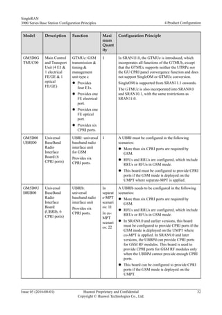
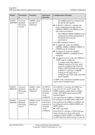
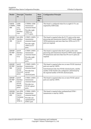
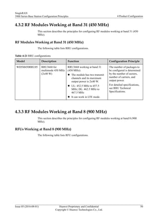
This document describes the principles for configuring hardware in 3900 series base stations. It provides definitions for base station components like BBUs, RRUs, and RFUs. It explains that 3900 series base stations use a modular design with BBUs and RF modules to support multiple radio access technologies (RATs) and installation scenarios. The BBU and RF modules can support single-mode and multi-mode configurations through software configurations to provide flexibility for network deployment and evolution.


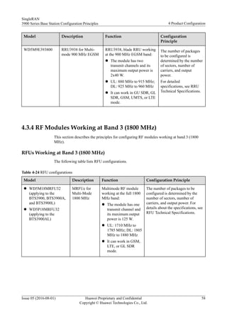
![GSM, UMTS, and LTE using different software configurations. A base station can
be configured with single-mode RF modules of GSM, UMTS, and LTE and
multimode RF modules to support any single mode as well as two or three modes
including GSM, UMTS, and LTE.
– RF modules working in different frequency bands can be used together to support
multi-band applications.
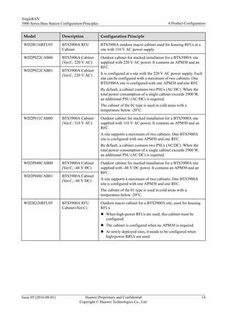
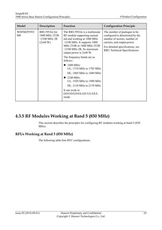
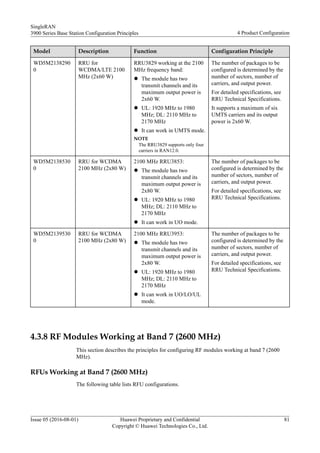
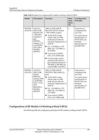
– High-power RFUs are as follows: MRFUd/MRFUe/WRFUd/WRFUe/LRFUe/
CRFUd/CRFUe. These RFUs are used together with the BTS3900 (Ver.C)/(Ver.D)/
(Ver.E) cabinets.
– High-power RRUs are as follows: RRU3829/RRU3929/RRU3942/RRU3841/
RRU3961/RRU3832/RRU3839/RRU3939/RRU3952/RRU3959/RRU3262/
RRU3953/RRU3962/RRU3962d/RRU3965/RRU3965d. These RRUs are used
together with the DCDU-11B or DCDU-12B. Ultra-high-power RRUs are used
together with the DCDU-12B. Except the preceding RRUs, other RRUs are low-
power ones. In addition, the 2100 MHz AAU3910, AWS AAU3910, AAU3920,
AAU3940, and AAU3911 are also high-power modules.
– Blade RRUs are as follows: RRU3962/RRU3965/RRU3936/RRU3938/RRU3939/
RRU3953/RRU3952/RRU3959/RRU3958/RRU3971/RRU3668/RRU3824/
RRU3826/RRU3838/RRU3832/RRU3839, and RRU3268/RRU3260/RRU3262/
RRU3249/RRU3269/RRU3281.
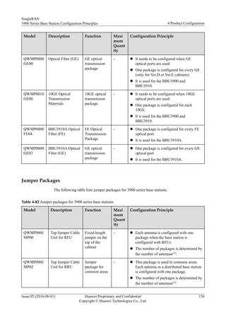
Description
The following table describes the meanings of some symbols and phrases in this document.
Table 2-1 Symbol meanings
Symbol Meaning
& It is used between different modes in a separate-MPT base station. For example,
GSM&UMTS, which can be shortened to GU, indicates a separate-MPT GU dual-mode
base station.
* It is used between different modes in a co-MPT base station. For example, GSM*UMTS,
which can be shortened to G*U, indicates a co-MPT GU dual-mode base station.
+ It is used between different modes for the two BBUs in a separate-MPT base station. For
example, GSM&UMTS+LTE, which can be shortened to GU+L, indicates a separate-MPT
GUL triple-mode base station.
[] [] contains co-MPT modes. For example, GSM[UMTS*LTE] can be shortened to G[U*L].
_ The underline and letters following a board's name is the actual configuration of the board
such as the co-MPT configuration of a UMPT and the baseband concurrency configuration
of a UBBP. For example, UMPT_GUL refers to a UMPT supporting GUL triple modes;
UBBP_UL refers to a UBBP supporting UL dual modes.
GU SDR GSM and UMTS share RF modules.
GL SDR GSM and LTE share RF modules.
UL SDR UMTS and LTE share RF modules.
GUL SDR GSM, UMTS, and LTE share RF modules.
SingleRAN
3900 Series Base Station Configuration Principles 2 Overview
Issue 05 (2016-08-01) Huawei Proprietary and Confidential
Copyright © Huawei Technologies Co., Ltd.
5](https://image.slidesharecdn.com/huaweisransiteconfigrationprinciples-210422124900/85/Huawei-sran-site-configration-principles-9-320.jpg)

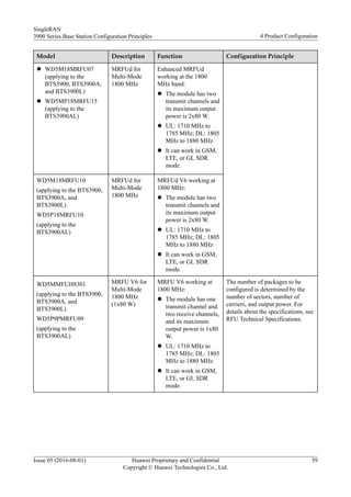
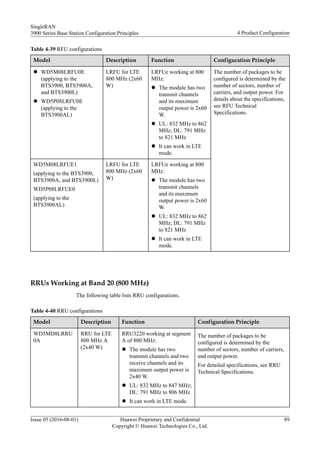
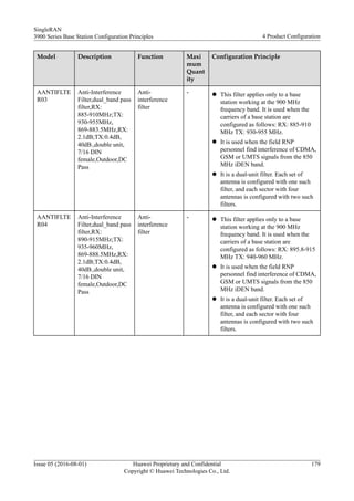
![(delivered in SRAN10.1, supported from SRAN8.0), 1800 MHz 2T2R 2x60 W
RRU3959w (delivered in SRAN10.1, supported from SRAN8.0), 700 MHz 2T4R 2x60
W RRU3262, 2600 MHz 2T2R 2x60 W LRFUe, 700 MHz band 12 RRU3249, and 700
MHz band 12&13 RRU3269.
l Added the BBU3900A1 and BBU3910A2.
l Added distributed Cloud BB scenarios.
SRAN10.0
The single-mode versions for SRAN10.0 are GBSS17.0, RAN17.0, and eRAN8.0. Compared
with SRAN9.0, SRAN10.0 includes the following changes:
l Added the BBU3910A3.
l Added the AAU3911.
l Added power modules: OPM50M and IBBS20D.
l Added the USU3910 for Cloud BB.
SRAN9.0
The single-mode versions for SRAN9.0 are GBSS16.0, RAN16.0, and eRAN7.0. Compared
with SRAN8.0, SRAN9.0 includes the following changes:
l Added the AAU3902 working as a 1.8 A module in GL mode.
l Added the UBBP and BBU3910. A BBU3910 can be installed in the following cabinets:
BTS3900 (Ver.D), BTS3900L (Ver.D), BTS3900A (Ver.D), APM30H (Ver.D), TMC11H
(Ver.D), IMB03, OMB (Ver.C) (applies to DBS3900 and BTS3900C [Ver.C]), and
BTS3900AL (Ver.A). Added the RRU3262 working in 2600 MHz and APT700M
LRFUe.
l Added the multimode baseband license.
l Added the ODM and OFD.
SRAN8.1
The single-mode versions for SRAN8.1 are GBSS15.1, RAN15.1, and eRAN6.1. Compared
with SRAN8.0, SRAN8.1 includes the following changes:
l Added the following RF modules: RRU3938 working at the EGSM, PGSM, and 1800
MHz frequency bands and enhanced MRFUd working at the EGSM, PGSM, and 1800
MHz frequency bands
l Added the RRU3268 working at 800 MHz for eRAN6.1.
l Added the AAU3902 working as a 1.8 A module in LO mode.
l Added the support for the GULT quadruple mode.
SRAN8.0
The single-mode versions for SRAN8.0 are GBSS15.0, RAN15.0, and eRAN6.0. Compared
with SRAN7.0, SRAN8.0 includes the following changes:
l Added the following BBU boards: UBRIb, UMPTb1, LBBPd3 (LTE baseband
processing unit), UTRPa (UMTS transmission processing unit), and UBBPd1/UBBPd2/
UBBPd3/UBBPd4 (UMTS baseband processing unit).
SingleRAN
3900 Series Base Station Configuration Principles 3 Version Difference
Issue 05 (2016-08-01) Huawei Proprietary and Confidential
Copyright © Huawei Technologies Co., Ltd.
7](https://image.slidesharecdn.com/huaweisransiteconfigrationprinciples-210422124900/85/Huawei-sran-site-configration-principles-11-320.jpg)


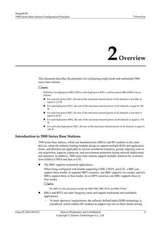
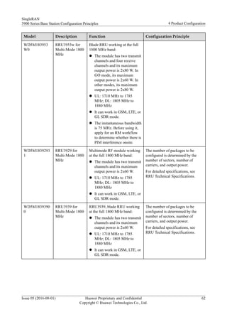
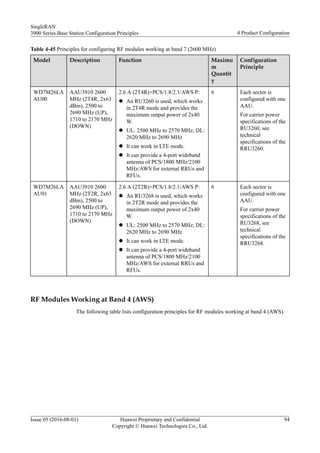
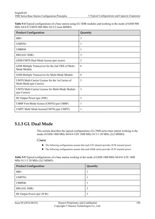
![Single/Dual/
Triple-Mode
Base Station
Configured
Mode
BBU Case Configuration Principles
UT Two modes share one BBU configured in WMPT/UMPT_U+LMPT/
UMPT_T mode.
L*T Two modes share one BBU in which the UMPT_L*T is configured.
Separate-MPT
triple-mode
base station
GU+L Two BBUs are configured, one shared by GSM and UMTS modes and the
other independently used by the LTE mode.
GL+U Two BBUs are configured, one shared by GSM and LTE modes and the other
independently used by the UMTS mode.
GU+UL Two BBUs are configured, one shared by GSM and UMTS modes and the
other shared by UMTS and LTE modes.
GU+L(G) Two BBUs are configured, one shared by GSM and UMTS modes and the
other independently used by the LTE mode. The two BBUs are
interconnected.
GL+U(G) Two BBUs are configured, one shared by GSM and LTE modes and the other
independently used by the UMTS mode. The two BBUs are interconnected.
GU+UL(G) Two BBUs are configured, one shared by GSM and UMTS modes and the
other shared by UMTS and LTE modes. The two BBUs are interconnected.
G[U*L] Three modes share one BBU. The UMTS and LTE FDD modes share the
UMPT_U*L while the GSM mode uses the GTMU.
G[L*T] Three modes share one BBU. The LTE FDD and LTE TDD modes share the
UMPT_L*T while the GSM mode uses the GTMU.
U[L*T] Three modes share one BBU. The LTE FDD and LTE TDD modes share the
UMPT_L*T while the UMTS mode uses the WMPT/UMPT_U.
G[U*T] Three modes share one BBU. The UMTS and LTE TDD modes share the
UMPT_U*T while the GSM mode uses the GTMU.
L[G*U] Three modes share one BBU. The GSM and UMTS modes share the
UMPT_G*U while the GSM mode uses the LMPT/UMPT_L.
Co-MPT
triple-mode
base station
G*U*L Three modes share one BBU in which the UMPT_G*U*L is configured.
G*U*T Three modes share one BBU in which the UMPT_G*U*T is configured.
G*L*T Three modes share one BBU in which the UMPT_G*L*T is configured.
U*L*T Three modes share one BBU in which the UMPT_U*L*T is configured.
Co-MPT
quadruple-
mode base
station
G*U*L*T Four modes share one BBU in which the UMPT_G*U*L*T is configured.
GU+[L*T]
(G)
Two BBUs are configured, one shared by GSM and UMTS modes and the
other shared by LTE FDD and LTE TDD modes. GSM and UMTS are
deployed on different main control boards, and LTE FDD and LTE TDD are
deployed on the same main control board. The two BBUs are interconnected.
SingleRAN
3900 Series Base Station Configuration Principles 4 Product Configuration
Issue 05 (2016-08-01) Huawei Proprietary and Confidential
Copyright © Huawei Technologies Co., Ltd.
22](https://image.slidesharecdn.com/huaweisransiteconfigrationprinciples-210422124900/85/Huawei-sran-site-configration-principles-26-320.jpg)

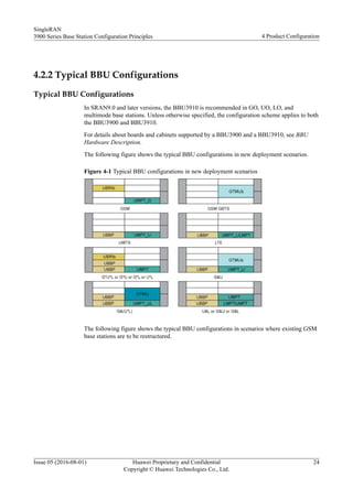

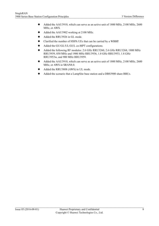
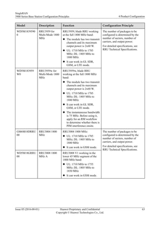
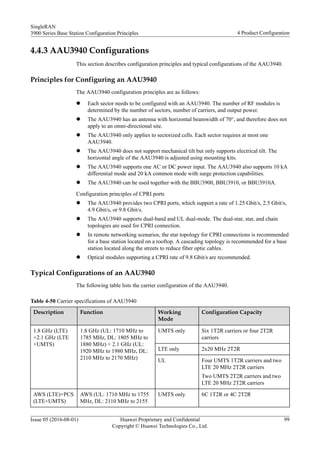
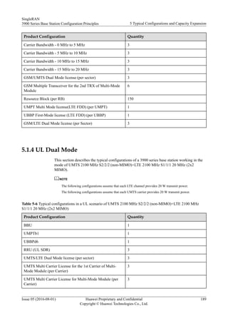
![Figure 4-4 Typical BBU configurations in scenarios with signaling extension
The following table lists the features supported by BBUs of different versions.
Version Supported Feature
SRAN6.0 GU+L (BBUs not interconnected) and GL+U (BBUs not interconnected)
are supported.
SRAN7.0 GU+L(GSM), GL+U(GSM), GU+UL, and GU+UL(GSM) are supported.
SDR RF modules are connected to two BBU3900s. Therefore, BBU3900s
need to be interconnected. In this case, the two BBU3900s are
interconnected by connecting the UCIU in the root BBU and the UMPT in
the leaf BBU.
SRAN8.0 From SRAN8.0 onwards, the multimode co-MPT application is
supported, including the following configurations: G*U, G*L, U*L,
G*U*L, and G[U*L].
In SRAN8.0, a single BBU3900 is recommended for the co-MPT
solution. If two BBUs are required for the co-MPT solution, only the basic
interconnection through UCIU+UMPT can be used.
SRAN8.1 The GULT quadruple-mode application and the basic interconnection
through UMPT+UMPT are supported.
SingleRAN
3900 Series Base Station Configuration Principles 4 Product Configuration
Issue 05 (2016-08-01) Huawei Proprietary and Confidential
Copyright © Huawei Technologies Co., Ltd.
26](https://image.slidesharecdn.com/huaweisransiteconfigrationprinciples-210422124900/85/Huawei-sran-site-configration-principles-30-320.jpg)
![Version Supported Feature
SRAN9.0 l The BBU3910 (with a fully-interconnected backplane) is supported
and it supports enhanced board interconnection technologies.
l Co-MPT and hybrid-MPT dual-BBU base stations support applications
such as [G*U*L]+[G*U*L] and G[U*L]+[U*L]. If each BBU is
configured with a UMPT, the UMPT+UMPT interconnection mode is
recommended as an alternative for the UCIU+UMPT interconnection
mode, which is supported since SRAN7.0.
l The GUL co-BBP technique is supported, which means that multiple
modes including GSM, UMTS, and LTE can be concurrently
configured on one baseband processing board. The co-BBP technique
is supported only by co-MPT base stations, not by separate-MPT base
stations.
SRAN10.0 The BBU3910A3 is supported, which can work in GSM only, UMTS
only, or LTE only mode and the three modes can be reconfigured to one
another. In addition, the BBU3910A3 can work in GU/GL/UL/GUL co-
MPT and co-BBP modes.
SRAN10.1 l LTE FDD and LTE TDD co-MPT is supported.
l The BBU3910A1 and BBU3910A2 are supported, which can work in
GSM only, UMTS only, or LTE only mode and the three modes can be
reconfigured to one another. In addition, the BBU3910A1 and
BBU3910A2 can work in GU/GL/UL co-MPT mode.
NOTE
In SRAN10.0 and SRAN10.1, a BBU3910A cannot be interconnected with a
BBU3900, BBU3910, or BBU3910A.
SRAN11.0 The GTMUc is supported.
SRAN11.1 The multimode co-MPT board UMPTe and multimode co-BBP board
UBBPe are supported.
CPRI Networking Configurations
The slot constraints and limitations in CPRI networking configuration apply only to the
BBU3900.
CPRI networking configurations in separate-MPT scenarios
In separate-MPT scenarios where multimode SDR RF modules are used, the dual-star CPRI
networking topology is recommended. In this networking topology, a CPRI fiber optic cable
from the baseband processing board of each mode is connected to its corresponding RF
modules.
SingleRAN
3900 Series Base Station Configuration Principles 4 Product Configuration
Issue 05 (2016-08-01) Huawei Proprietary and Confidential
Copyright © Huawei Technologies Co., Ltd.
27](https://image.slidesharecdn.com/huaweisransiteconfigrationprinciples-210422124900/85/Huawei-sran-site-configration-principles-31-320.jpg)


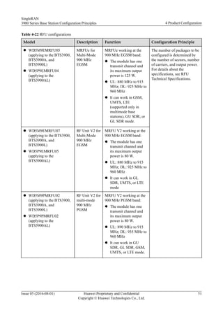


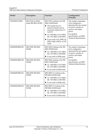


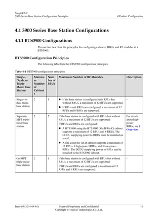
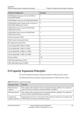
![Product Configuration Quantity (S2/2/2 Non-
MIMO)
Quantity (S2/2/2/2/2/2 Non-
MIMO)
Power License (per 20W) 3 6
UBBP First-Mode license (UMTS) (per
UBBP)
1 2
Typical Configuration of an LTE Base Station
The following describes typical configurations in scenarios of S1/1/1 20 MHz (DL 2x2
MIMO) and S1/1/1 20 MHz (DL 4x4 MIMO).
NOTE
This section assumes that each channel provides 20 W power.
Table 5-3 Typical configurations of an LTE base station using the RRU3201
Product Configuration Quantity (S1/1/1 20 MHz
[DL 2x2 MIMO])
Quantity (S1/1/1 20 MHz
[DL 4x4 MIMO])
BBU 1 1
UMPTb1 1 1
UBBPd6 1 1
RRU (2T2R) 3 6
RF Output Power (per 20W) 3 6
Carrier Bandwidth - 0 MHz to 5 MHz 3 3
Carrier Bandwidth - 5 MHz to 10 MHz 3 3
Carrier Bandwidth - 10 MHz to 15 MHz 3 3
Carrier Bandwidth - 15 MHz to 20 MHz 3 3
Resource Block (per RB) 150 150
5.1.2 GU Dual Mode
This section describes the typical configurations of a 3900 series base station working in the
mode of GSM 900 MHz S4/4/4+UMTS 900 MHz S2/2/2 (non-MIMO).
NOTE
Each UMTS carrier supports 20 W power.
SingleRAN
3900 Series Base Station Configuration Principles 5 Typical Configurations and Capacity Expansion
Issue 05 (2016-08-01) Huawei Proprietary and Confidential
Copyright © Huawei Technologies Co., Ltd.
187](https://image.slidesharecdn.com/huaweisransiteconfigrationprinciples-210422124900/85/Huawei-sran-site-configration-principles-191-320.jpg)


![E ran2[1].1 dbs3900 lte fdd product description(2011q1)](https://cdn.slidesharecdn.com/ss_thumbnails/eran21-1dbs3900ltefddproductdescription2011q1-120823005128-phpapp02-thumbnail.jpg?width=640&height=640&fit=bounds)


