Download to read offline
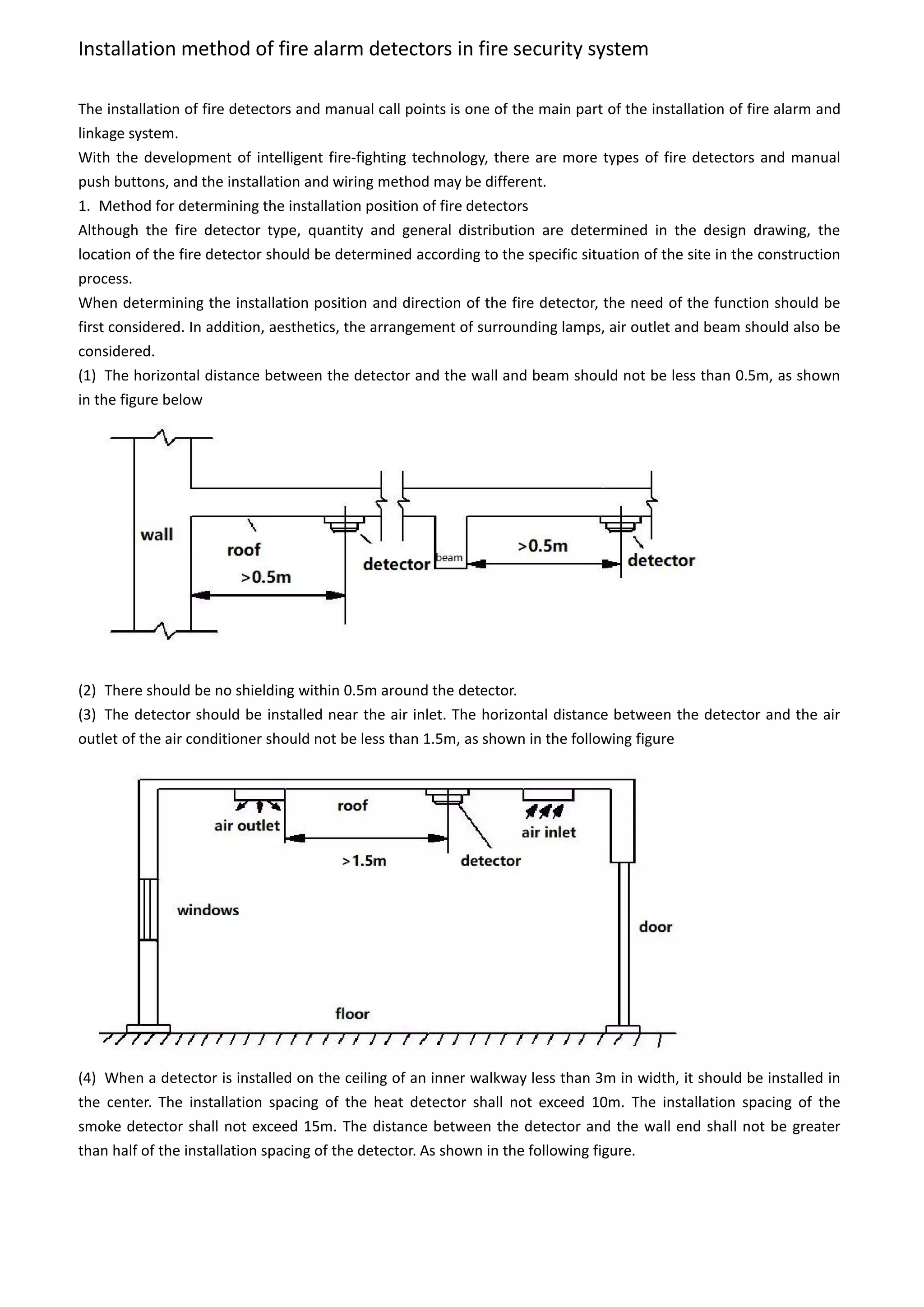
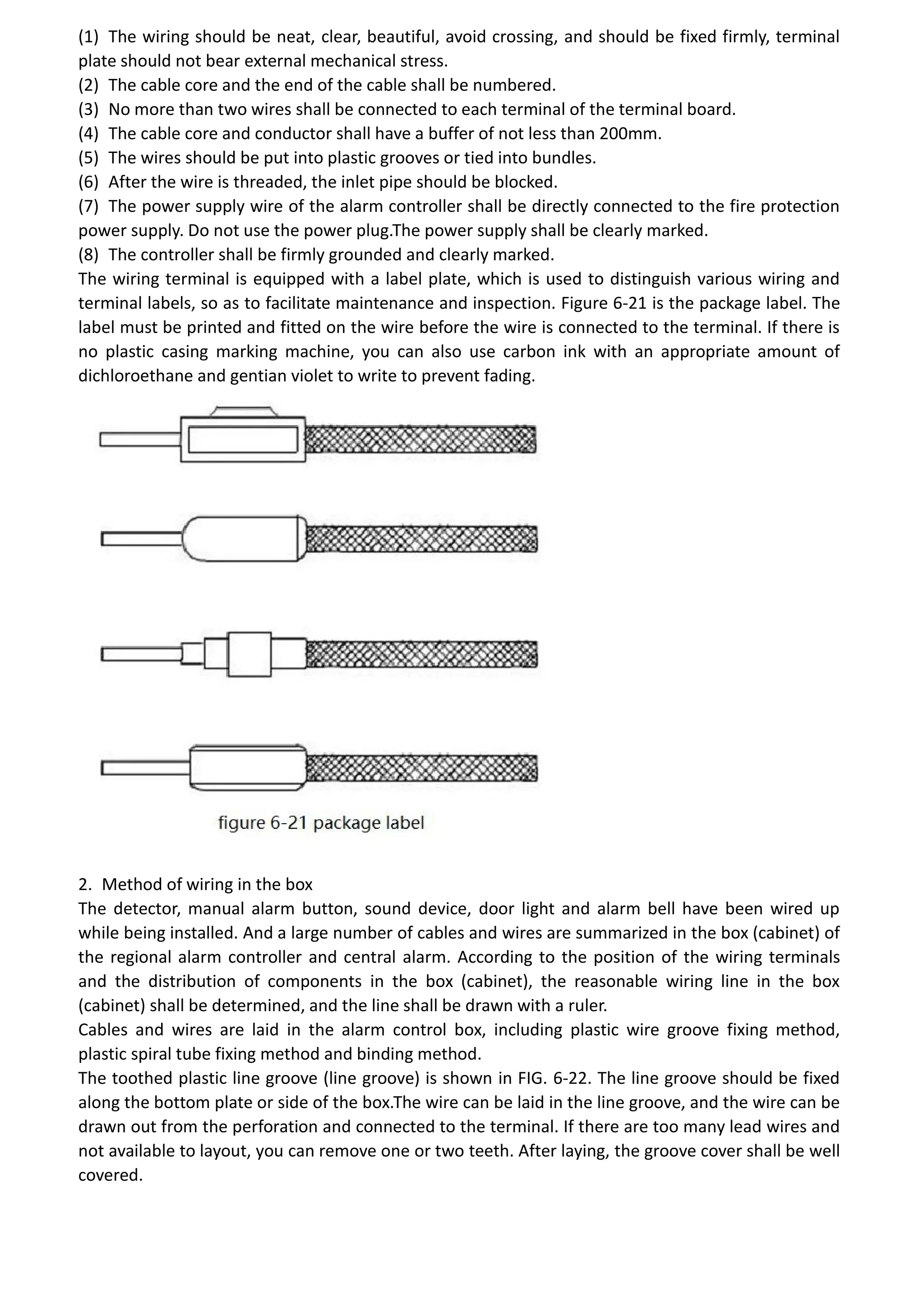
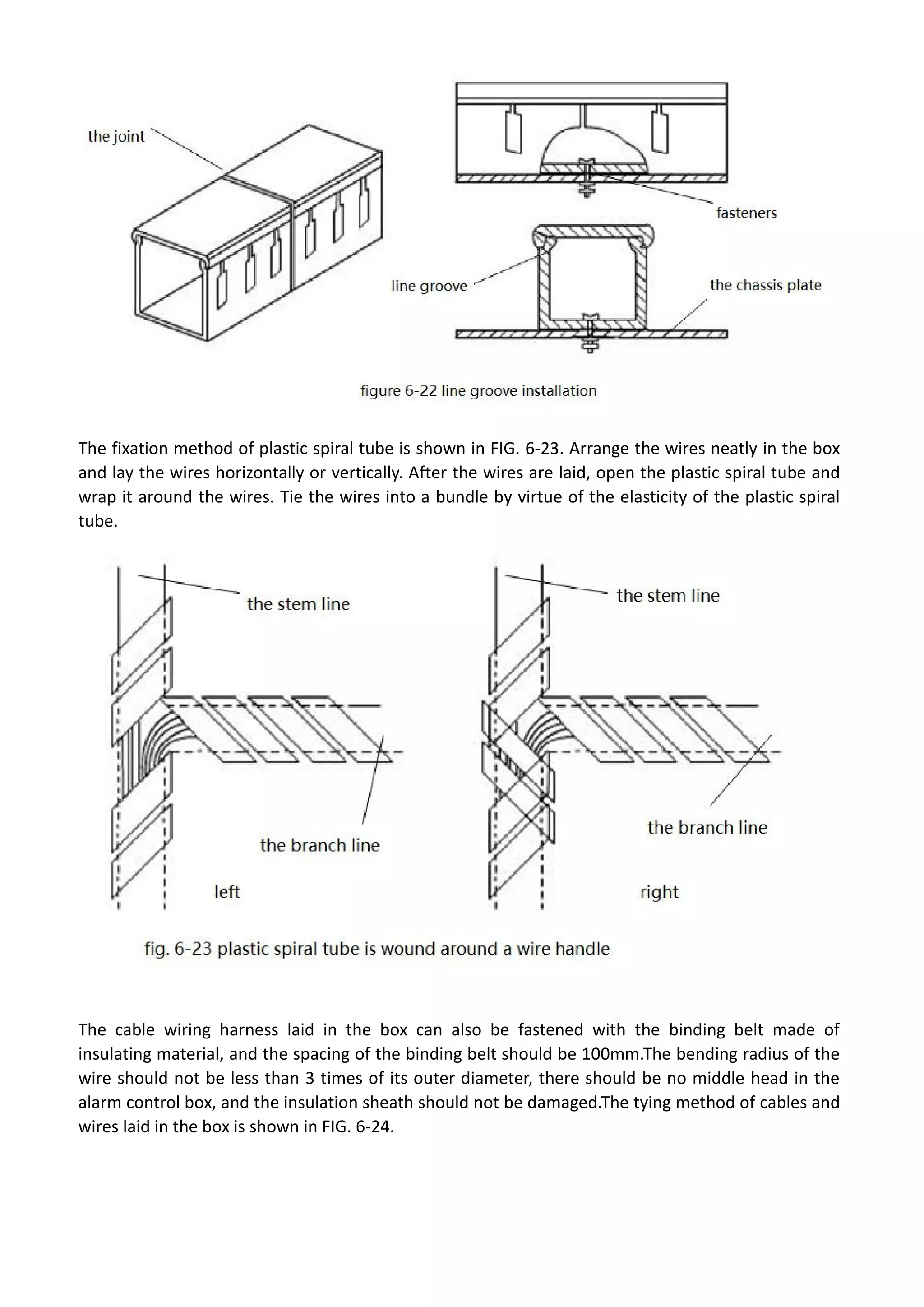
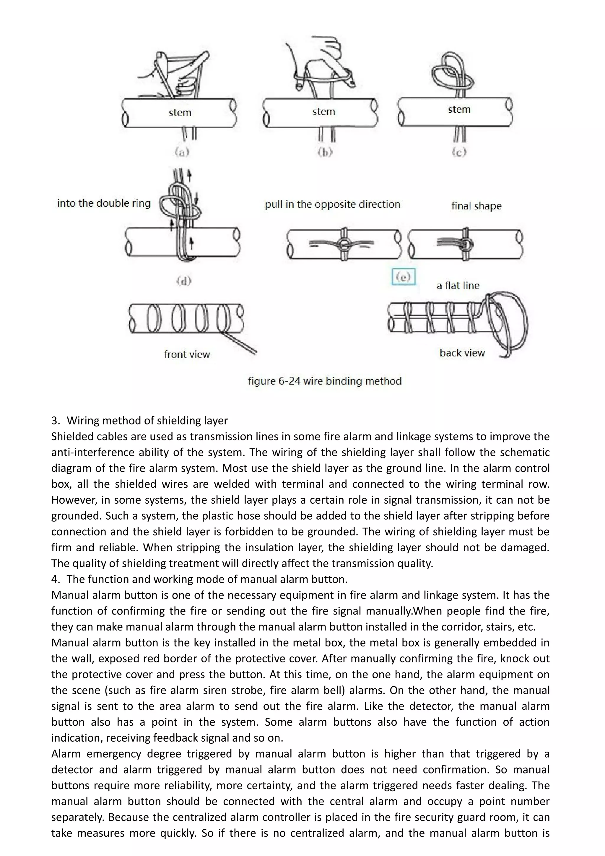
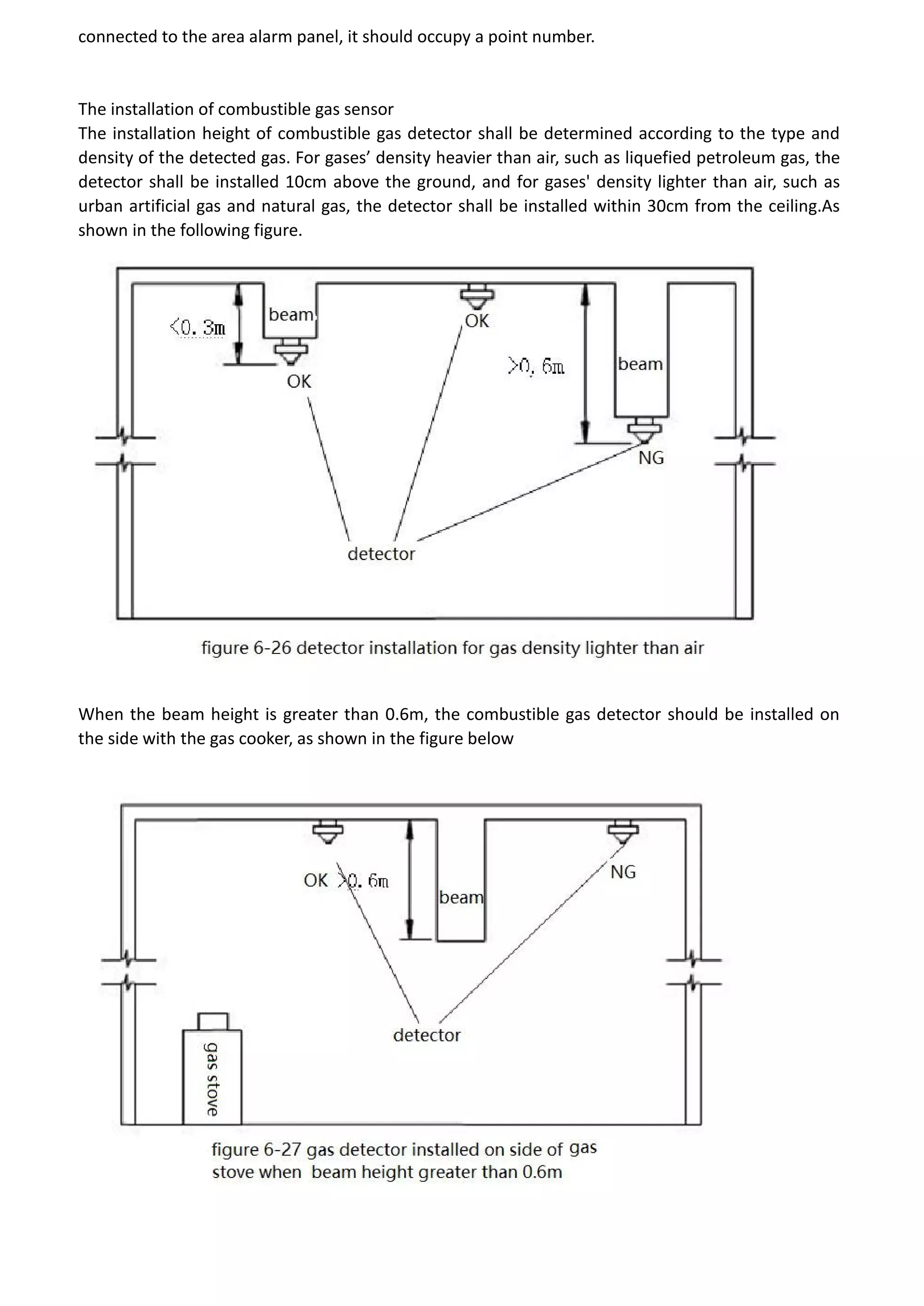

This document outlines the installation methods for fire alarm detectors and manual call points, detailing specific placement requirements based on various conditions such as detector type, site specifications, and building structure. It covers installation positioning for detectors, including proximity to walls and air outlets, as well as guidelines for manual alarm button placement and wiring procedures. Additionally, it details the importance of proper terminal connections and the functionality of manual alarm buttons in emergency situations.


