SlideShare a Scribd company logo
Include to or Exclude from a Z-WaveTM Network

SF812 SMOKE DETECTOR

Inside the detector, there is a link key which is used to carry out the function of
inclusion, exclusion, association and reset. When first power is applied, its LED
flashes on and off alternately and repeatedly for 4 minutes, which implies that it
has not been assigned a node ID and cannot work with Z-Wave enabled devices.
Please get familiar with the terms below before starting the operations.

The photoelectric Smoke Detector is a Z-WaveTM enabled device which is fully
compatible with any Z-WaveTM enabled network. Z-WaveTM enabled devices
displaying the Z-WaveTM logo can also be used with it regardless of the
manufacturer, and ours can also be used in other manufacturer’s Z-WaveTM
enabled networks. Inclusion of this detector on other manufacturer’s Wireless
Controller menu allows remote operation of connected modules when the
detector is triggered. Z-Wave node in the system also acts as a repeater, so as
to re-transmit the RF signal to ensure that the signal is received by its intended
destination by routing the signal around obstacles and radio dead spots.

Function
Inclusion
Exclusion

The detector is designed to sense smoke that comes into the detector chamber.
It does not sense gas, heat, or flame. The working principle is when the smoke
detector detects a certain density of smoke, the horn of smoke detector will
sound and in the meantime, the detector will emit the signals to the associated
devices for further execution. It can provide precious time for you and your
family to escape before a fire spreads.

Association

Reset

Description
Add a Z-Wave enabled device (e.g. Smoke Detector) to Z-Wave
network.
Delete a Z-Wave enabled device (e.g. Smoke Detector) from the
network.
After inclusion, you have to define the relationship between devices.
Trough association, device can be assigned as master/slave, and
specify which slave is going to be controlled by which master.
Restore Smoke Detector to factory default.

The table below lists an operation summary of basic Z-Wave functions. Please
refer to the instructions for your Z-WaveTM Certificated Primary Controller to
access the setup function, and to include/exclude/associate devices.

Product Overview
5

Action/Status

4

Description

Link LED Indication

No node ID

The Z-Wave Controller does not allocate

2-second on, 2-second off

6

a node ID to the detector.
1.
2.

Have Z-Wave Controller entered

Flashes when link key is

inclusion mode.

Inclusion

pressed

Pressing link key three times within 1.5
second will enter inclusion mode. The
Detector will stay “awake” for 10
minutes to allow time for setting and
device status enquiring.

1.
2.

Flashes when link key is

exclusion mode.

Exclusion

Have Z-Wave Controller entered

pressed

Pressing link key three times within 1.5
second will enter exclusion mode.

Horn
Test Button
LED
Connector’s Hole
Cover Latch
Battery Cover

Link Key
Connector
Tamper Switch
Link LED
Mounting Bracket

The Detector will stay “awake” for 10
minutes to allow time for setting and
device status enquiring.
Node ID has been excluded.

1

2-second on, 2-second off
Action/Status

Description

Link LED Indication

1.

Pressing link key three times within 1.5

Flashes when link key is

second will enter exclusion mode

pressed

2.

Within 1 second, press link key again

LED is on for 5 seconds

3.

Node ID is excluded, and it sets the

Reset

FIGURE 1
Locations for placing smoke
detectors for single residence with
only one sleeping area.

and hold it until LED is off
2-second on, 2-second off

device back to factory default state.
1.

Have Z-Wave Controller entered

Flashes when link key is

association mode.

Association

pressed

2.

Pressing link key 3 times within 1.5

3.

Refer to group support as described

second will enter association mode

FIGURE 2
Locations for placing smoke
detectors for single-floor residence
with more than one sleeping area.

on page 5
Failed or success in including/excluding the node ID can be viewed from the Z-Wave Controller.

Choosing a Mounting Location
The detector is designed for use in a single residential unit only, such as a single
family home or apartment. It is not meant to be used in lobbies, hallways,
basements, or another apartment in multi-family buildings, unless there are
already working detectors in each family unit. Smoke detectors, placed in
common areas outside of the individual living unit, such as on porches or in
hallways, may not provide early warning to residents. In multi-family buildings,
each family living unit should set up its own detectors.

2. Install a detector on every floor of a multi-floor home or apartment as shown
in FIGURE 3.

FIGURE 3
Locations for placing smoke
detectors for a multi-floor
residence.

The detector is not meant to be used in non-residential buildings. Warehouses,
industrial or commercial buildings, and special purpose non-residential buildings
require special fire detection and alarm systems. This detector is not a suitable
substitute for complete fire detection systems for places where many people live
or work, such as hotels or motels. The same is true of dormitories, hospitals,
nursing homes or group homes of any kind, even if they were once single family
homes.

3. Install a minimum of two detectors in any household.
4. Install a detector inside every bedroom.
5. Install smoke detectors at both ends of a bedroom hallway if the hallway is
more than 40 feet (12 meters) long.
6. Install a detector inside every room where one sleeps with the door partly or
completely closed, since smoke could be blocked by the closed door and a
hallway alarm may not wake up the sleeper if the door is closed.
7. Install detectors as close to the center of the ceiling as possible. If this is
not practical, put the detector on the ceiling, no closer than 4 inches (10 cm)
from any wall or corner as shown in FIGURE 4.

For complete coverage in residential units, it should be installed in all rooms,
halls, storage areas, basements and attics in each family living unit. Minimum
coverage is one detector on each floor and one in each sleeping area. Useful
tips are listed hereunder:
1. Install a detector in the hallway outside every separate bedroom area as
shown in FIGURE 1. Two detectors are required in homes with two
bedroom areas as shown in FIGURE 2.
2
distance is not possible, e.g. in a mobile home, try to install the detector as
far away from the combustion particles as possible, preferably on the wall.
To prevent nuisance alarms, provide good ventilation in such places.
IMPORTANT: For any reason, do not disable the detector to avoid nuisance
alarms.

FIGURE 4
Recommended best and
acceptable locations to
mount smoke detectors.

3. When air streams passing by kitchens, the way how a detector can sense
combustion particles in normal air-flow paths is graphically shown in
FIGURE 6, which indicates the correct and incorrect smoke detector
locations concerning this problem.

8. If ceiling mounting is not possible, put wall-mounted detectors between 4
and 6 inches (10~15 cm) from the ceiling (FIGURE 4).
9. If some of your rooms have sloped, peaked, or gabled ceilings, try to mount
detectors 3 feet (0.9 meter) measured horizontally from the highest point of
the ceiling as shown in FIGURE 5.

FIGURE 6
Recommended smoke detector locations
to avoid air streams with combustion
particles.

FIGURE 5
Recommended location to
mount smoke detectors in
rooms with sloped, gabled
or peaked ceiling.

4. In damp or very humid areas, or near bathrooms with showers. Moisture in
humid air can enter the sensing chamber, then turns into droplets upon
cooling, which can cause nuisance alarms. Install detectors at least 10 feet
(3 meters) away from bathrooms.
5. In very cold or very hot areas, including unheated buildings or outdoor
rooms. If the temperature goes above or below the operating range of
smoke detector, it will not work properly. The temperature range for your
smoke detector is 4°C to 38°C (40°F to 100°F).
6. In very dusty or dirty areas, dirt and dust can build up on the detector’s
sensing chamber, to make it overly sensitive. Additionally, dust or dirt can
block openings to the sensing chamber and keep the detector from sensing
smoke.
7. Near fresh air vents or very drafty areas like air conditioners, heaters or fans,
fresh air vents and drafts can drive smoke away from smoke detectors.
8. Dead air spaces are often at the top of a peaked roof, or in the corners
between ceilings and walls. Dead air may prevent smoke from reaching a
detector. Refer to FIGURE 4 and 5 for recommended mounting locations.
9. In insect-infested areas, it is probable that the insects may enter a detector’s

Locations Not To Install the Detector
Nuisance alarms take place when smoke detectors are installed where they will
not work properly. To avoid nuisance alarms, do not install smoke detectors in
the following situations:
1. Combustion particles are the by-products of something that is burning.
Thus, in or near areas where combustion particles are present you do not
install the smoke detectors to avoid nuisance alarms, such as kitchens with
few windows or poor ventilation, garages where there may be vehicle
exhaust, near furnaces, hot water heaters, and space heaters.
2. Do not install smoke detectors less than 20 feet (6 meters) away from places
where combustion particles are normally present, like kitchens. If a 20-foot
3
sensing chamber to cause a nuisance alarm. Where bugs are a problem,
please get rid of them before putting up a detector.
10. Near fluorescent lights, electrical “noise” from fluorescent lights may cause
nuisance alarms. Install smoke detectors at least 5 feet (1.5 meters) away
from such lights.
WARNING: Never remove batteries to stop a nuisance alarm. Cooking smoke or
a dusty furnace, sometimes called “friendly fires” can cause the alarm to sound.
If this happens, open a window or fan the air around the detector to get rid of the
smoke or dust. The alarm will turn itself off when the smoke is gone. If
nuisance alarms persist, attempt to clean the detector as described in this
Manual.

FIGURE 8

FIGURE 9

8. The steps to open the battery cover and to install the battery are listed as
follows:
a. To power the detector requires a 9V alkaline battery.
b. Open the battery cover and connect the battery with +ve and –ve in the
correct position. Push battery firmly in until it snaps and cannot be shaken
loose.
NOTE: It comes with cover latches that will prevent the battery cover
from closing if battery is not installed. (FIGURE 9) This tells you that the
smoke detector will not work until a new battery is properly installed.
c. Place the connector to the connector hole. Ensure that the direction of
connector is inserted correctly according to the sticker affixed on the
detector. (FIGURE 10)

WARNING: Do not stand close to the detector when the alarm is sounding. The
alarm is loud in order to wake you in an emergency. Too much exposure to the
horn at close range may be harmful to your hearing.

Installation
1. At the place where you are going to install the detector, draw a horizontal line
six inches long.
2. Remove the mounting bracket from the detector by rotating it counterclockwise.
(FIGURE 7)

FIGURE 7
3. Place the bracket so that the two longest hole slots are aligned on the line. In
each of keyhole slots, draw a mark to locate a mounting plug and screw.
4. Remove the bracket.
5. Using a 3/16-inch (5mm) drill bit, drills two holes at the marks and insert plastic
wall plugs. Put the detector away from getting plaster dust on it when you drill
holes for mounting.
6. Using the two screws and plastic wall plugs (all supplied), attach the bracket to
the wall.
7. Line up the slot of the bracket and the detector. Push the detector onto the
mounting bracket and turn it clockwise to fix it into place. (FIGURE 8) Pull
outward on the detector to make sure it is securely attached to the mounting
bracket.

FIGURE 10

Operation
1. The detector sounds as long as the test button is pressed for 3 seconds or
there is smoke in the detector. When the detector goes off, always check
carefully to see that there is no fire and never remove the battery from the
detector except when changing it!
2. Always test the detector immediately after returning from holiday, after a longer
period of absence or periodically to ensure the detector funtions normally.
Under the test button, there is a red control LED which flashes once every 30
4
SENSOR_ALARM_REPORT

seconds. It indicates the detector is under normal operation. When Smoke
Detector senses smoke and simultaneously sounds an audible alarm, the red
LED will flash frequently, once 0.67 seconds. If the detector does not sound
when testing, the battery must be replaced.

Event Present:
[Command Class Sensor Alarm, Sensor Alarm Report, Sensor Type
Smoke Alarm State = 255 (0 x FF), Seconds = 0x00]

WARNING: Never use an open flame to test your detector. You may set fire to
damage the detector, as well as your home.

Event Clear:
[Command Class Sensor Alarm, Sensor Alarm Report, Sensor Type
Smoke Alarm State = 0, Seconds = 0x00]

WARNING: When you are not testing the unit and the alarm horn sounds a loud
continuous sound, this means the detector has sensed smoke or combustion
particles in the air. Be sure that the alarm horn is a warning of a possible
serious situation, which requires your immediate attention.

1.3 Tamper Trigger Report
When the tamper is triggered (that is, the detector is opened with tamper switch
being released), the detector will emit ALARM_REPORT command to the
nodes of Grouping 1.

Programming

ALARM_REPORT Command:
[Command Class Alarm, Alarm Type = 0x01, Alarm Level = 17(0x11)]

1. Z-Wave’s Group (Association Command Class Version 2)
The Smoke Detector supports one association group with five nodes. This has
the effect that when the detector is triggered, all devices associated with the
detector will receive the relevant reports. There are two main kinds of reports:
ALARM_REPORT and SENSOR_ALARM_REPORT. Please refer to the
sections below for more details on the reports that the detector will emit when
event occurs.

Note: If you press test button under low battery status while tamper switch is
released, the status LED will flash once.
1.4 Low Battery Report
When the battery level of the detector drops to an unacceptable level, the
detector will sound once every 30 seconds and send BATTERY_REPORT
command to the nodes of Grouping 1 once per hour.

1.1 POWER_APPLIED command
The Smoke Detector will send ALARM_REPORT command to the nodes of
Grouping 1 to inform the devices that the detector is powered up.

BATTERY_REPORT Command:
[Command Class Alarm, Alarm Type = 0x01, Alarm Level = 255(0xFF)]

ALARM_REPORT Command:
[Command Class Alarm, Alarm Type = 0x02, Alarm Level = 0x01]

The users can also enquire the battery status of the detector by sending
BATTERY_ GET command via controller, however, this procedure can only be
done during 5-second time allowance after the tamper switch/detector being
triggered or 10 minutes wakeup time when power is first applied. Once the
detector receives the command, it will return BATTERY_REPORT command.

1.2 Smoke Event Report
Once the detector has been triggered by smoke, the detector will send
SENSOR_ALARM_REPORT (Sensor State = 0xFF) to the nodes of Grouping 1
to inform them there is a smoke event; wait till the smoke is discharged,
SENSOR_ALARM_REPORT (Sensor State = 0x00) will be sent to the
associated devices.

BATTERY_REPORT Command:
[Command Class Battery, Battery Report, Battery Level = 20%-100%]
If it displays with a message of “Battery Level = 255 (0xFF)”, it implies that the
detector is at low battery status. Please replace the batteries as soon as
possible.
5
Specifications

2. Command Classes
The Smoke Detector supports Command Classes including…

Operating Frequency

* COMMAND_CLASS_BATTERY
* COMMAND_CLASS_VERISON
* COMMAND_CLASS_SENSOR_ALARM
* COMMAND_CLASS_ASSOCIATION_V2
* COMMAND_CLASS_MANUFACTURER_SPECIFIC

868.42 MHz (SF812-1) / 908.42 MHz (SF812-2)

Battery Type

9V alkaline battery x 1

Operating Range

Up to 30 meters line of sight (indoor)

ZDK Version

V5.02

*Specifications are subject to change without notice

A501111353R01

Maintenance
The smoke detector is preferably powered by a 9V alkaline battery which under
normal conditions will have typical life in excess of 1 year. Replace the battery
once a year. When changing the battery, clean and vacuum the dust off the
detector’s sensing chamber carefully using a soft brush.

Federal Communication Commission Interference Statement
This equipment has been tested and found to comply with the limits for a Class B
digital device, pursuant to Part 15 of the FCC Rules. These limits are designed
to provide reasonable protection against harmful interference in a residential
installation. This equipment generates, uses and can radiate radio frequency
energy and, if not installed and used in accordance with the instructions, may
cause harmful interference to radio communications. However, there is no
guarantee that interference will not occur in a particular installation. If this
equipment does cause harmful interference to radio or television reception,
which can be determined by turning the equipment off and on, the user is
encouraged to try to correct the interference by one of the following measures:

Troubleshooting
Symptom

Possible Cause

Recommendation

LED not illuminating, the
detector not working

Run out of battery power;
check if reverse battery
polarity
Check if the detector is our of
order

Replace a new battery

LED cannot be displayed
and the detector not
working when pressing
the test button

The detector does not
stay awake for 10 minutes
when power is first
supplied

Reverse battery polarity or
poor battery connections
Run out of battery power
Button pressing time is not
long enough; it should be
pressed and held for more
than 1 second
Check if detector is out of
order

Do not open the detector;
send it to the local
retailer.
Refit the battery with
correct polarity

-

Replace a new battery
Press and hold the button
for longer than 1 second

Reorient or relocate the receiving antenna.
Increase the separation between the equipment and receiver.
Connect the equipment into an outlet on a circuit different from that to which
the receiver is connected.
Consult the dealer or an experienced radio/TV technician for help.

This device complies with Part 15 of the FCC Rules. Operation is subject to the
following two conditions: (1) This device may not cause harmful interference,
and (2) this device must accept any interference received, including interference
that may cause undesired operation.

Remove
the
battery,
press link key several
times to release the
existing battery power
and wait for approx.10
seconds before replacing
the battery.

FCC Caution: Any changes or modifications not expressly approved by the party
responsible for compliance could void the user's authority to operate this
equipment.
This transmitter must not be co-located or operating in conjunction with any
other antenna or transmitter.
6
WARNING:
Do not dispose of electrical appliances as unsorted municipal waste, use
separate collection facilities.
Contact your local government for information regarding the collection systems
available.
If electrical appliances are disposed of in landfills or dumps, hazardous
substances can leak into the groundwater and get into the food chain, damaging
your health and well-being.
When replacing old appliances with new once, the retailer is legally obligated to
take back your old appliance for disposal at least for free of charge.

7

More Related Content

What's hot

Honeywell is25100tc-spec-sheet
Honeywell is25100tc-spec-sheetHoneywell is25100tc-spec-sheet
Honeywell is25100tc-spec-sheetAlarm Grid
 
System sensor 1400 manual i56-0279
System sensor 1400 manual i56-0279System sensor 1400 manual i56-0279
System sensor 1400 manual i56-0279
Henry Rosa
 
Takex DA-101E Instruction Manual
Takex DA-101E Instruction ManualTakex DA-101E Instruction Manual
Takex DA-101E Instruction Manual
JMAC Supply
 
Advantage and disadvantage of security systems
Advantage and disadvantage of security systemsAdvantage and disadvantage of security systems
Advantage and disadvantage of security systems
BeverlyIssac
 
MultiSensor Strips Comfort - Z-Wave Plus- Sensative - Manual
MultiSensor Strips Comfort - Z-Wave Plus- Sensative - ManualMultiSensor Strips Comfort - Z-Wave Plus- Sensative - Manual
MultiSensor Strips Comfort - Z-Wave Plus- Sensative - Manual
Domotica daVinci
 
Manual ES-12-ZIP-PD01Z PIR Z-Wave Plus motion sensor
Manual ES-12-ZIP-PD01Z PIR Z-Wave Plus motion sensorManual ES-12-ZIP-PD01Z PIR Z-Wave Plus motion sensor
Manual ES-12-ZIP-PD01Z PIR Z-Wave Plus motion sensor
Domotica daVinci
 
Honeywell is2560-spec-sheet
Honeywell is2560-spec-sheetHoneywell is2560-spec-sheet
Honeywell is2560-spec-sheetAlarm Grid
 
Manual Smoke Detector. Z-Wave Plus - Zipato
Manual Smoke Detector. Z-Wave Plus - ZipatoManual Smoke Detector. Z-Wave Plus - Zipato
Manual Smoke Detector. Z-Wave Plus - Zipato
Domotica daVinci
 
Security Alarm Systems blaze automation
Security Alarm Systems blaze automationSecurity Alarm Systems blaze automation
Security Alarm Systems blaze automation
Blaze Automation
 
Kaipu Lm20 Z-Wave Plus door contact user guide
Kaipu Lm20 Z-Wave Plus door contact user guideKaipu Lm20 Z-Wave Plus door contact user guide
Kaipu Lm20 Z-Wave Plus door contact user guide
Domotica daVinci
 
Sensative Door Window Sensor Strip Z-Wave Plus User Manual
Sensative Door Window Sensor Strip Z-Wave Plus User ManualSensative Door Window Sensor Strip Z-Wave Plus User Manual
Sensative Door Window Sensor Strip Z-Wave Plus User Manual
Domotica daVinci
 
SenseTek Stratos Micra 25 installers handbook
SenseTek Stratos Micra 25 installers handbookSenseTek Stratos Micra 25 installers handbook
SenseTek Stratos Micra 25 installers handbook
Hans Bronkhorst
 
Fibaro Flood Sensor presentation
Fibaro Flood Sensor presentationFibaro Flood Sensor presentation
Fibaro Flood Sensor presentation
Domotica daVinci
 
Ph psm02-zipato-multisensor-quad-user-manual-v1.4
Ph psm02-zipato-multisensor-quad-user-manual-v1.4Ph psm02-zipato-multisensor-quad-user-manual-v1.4
Ph psm02-zipato-multisensor-quad-user-manual-v1.4
Ana Roza Braña
 
Mh8 fc um
Mh8 fc umMh8 fc um
Mh8 fc um
Domotica daVinci
 
Mh7 eu um v.02
Mh7 eu um v.02Mh7 eu um v.02
Mh7 eu um v.02
Domotica daVinci
 
Safety siren pro series 3 radon gas detector user guide user manual
Safety siren pro series 3 radon gas detector user guide  user manualSafety siren pro series 3 radon gas detector user guide  user manual
Safety siren pro series 3 radon gas detector user guide user manual
Ashish Kamble
 
Manual Opening Detector with temeperature sensor Z-Wave Plus Version 2- Fibaro
Manual Opening Detector with temeperature sensor Z-Wave Plus Version 2- FibaroManual Opening Detector with temeperature sensor Z-Wave Plus Version 2- Fibaro
Manual Opening Detector with temeperature sensor Z-Wave Plus Version 2- Fibaro
Domotica daVinci
 
Manual Carbon Monoxide Sensor CO. Z-Wave Plus - Zipato
Manual Carbon Monoxide Sensor CO. Z-Wave Plus - ZipatoManual Carbon Monoxide Sensor CO. Z-Wave Plus - Zipato
Manual Carbon Monoxide Sensor CO. Z-Wave Plus - Zipato
Domotica daVinci
 
Ph psg01 - zipato smoke sensor user manual v1.0
Ph psg01 - zipato smoke sensor user manual v1.0Ph psg01 - zipato smoke sensor user manual v1.0
Ph psg01 - zipato smoke sensor user manual v1.0
Domotica daVinci
 

What's hot (20)

Honeywell is25100tc-spec-sheet
Honeywell is25100tc-spec-sheetHoneywell is25100tc-spec-sheet
Honeywell is25100tc-spec-sheet
 
System sensor 1400 manual i56-0279
System sensor 1400 manual i56-0279System sensor 1400 manual i56-0279
System sensor 1400 manual i56-0279
 
Takex DA-101E Instruction Manual
Takex DA-101E Instruction ManualTakex DA-101E Instruction Manual
Takex DA-101E Instruction Manual
 
Advantage and disadvantage of security systems
Advantage and disadvantage of security systemsAdvantage and disadvantage of security systems
Advantage and disadvantage of security systems
 
MultiSensor Strips Comfort - Z-Wave Plus- Sensative - Manual
MultiSensor Strips Comfort - Z-Wave Plus- Sensative - ManualMultiSensor Strips Comfort - Z-Wave Plus- Sensative - Manual
MultiSensor Strips Comfort - Z-Wave Plus- Sensative - Manual
 
Manual ES-12-ZIP-PD01Z PIR Z-Wave Plus motion sensor
Manual ES-12-ZIP-PD01Z PIR Z-Wave Plus motion sensorManual ES-12-ZIP-PD01Z PIR Z-Wave Plus motion sensor
Manual ES-12-ZIP-PD01Z PIR Z-Wave Plus motion sensor
 
Honeywell is2560-spec-sheet
Honeywell is2560-spec-sheetHoneywell is2560-spec-sheet
Honeywell is2560-spec-sheet
 
Manual Smoke Detector. Z-Wave Plus - Zipato
Manual Smoke Detector. Z-Wave Plus - ZipatoManual Smoke Detector. Z-Wave Plus - Zipato
Manual Smoke Detector. Z-Wave Plus - Zipato
 
Security Alarm Systems blaze automation
Security Alarm Systems blaze automationSecurity Alarm Systems blaze automation
Security Alarm Systems blaze automation
 
Kaipu Lm20 Z-Wave Plus door contact user guide
Kaipu Lm20 Z-Wave Plus door contact user guideKaipu Lm20 Z-Wave Plus door contact user guide
Kaipu Lm20 Z-Wave Plus door contact user guide
 
Sensative Door Window Sensor Strip Z-Wave Plus User Manual
Sensative Door Window Sensor Strip Z-Wave Plus User ManualSensative Door Window Sensor Strip Z-Wave Plus User Manual
Sensative Door Window Sensor Strip Z-Wave Plus User Manual
 
SenseTek Stratos Micra 25 installers handbook
SenseTek Stratos Micra 25 installers handbookSenseTek Stratos Micra 25 installers handbook
SenseTek Stratos Micra 25 installers handbook
 
Fibaro Flood Sensor presentation
Fibaro Flood Sensor presentationFibaro Flood Sensor presentation
Fibaro Flood Sensor presentation
 
Ph psm02-zipato-multisensor-quad-user-manual-v1.4
Ph psm02-zipato-multisensor-quad-user-manual-v1.4Ph psm02-zipato-multisensor-quad-user-manual-v1.4
Ph psm02-zipato-multisensor-quad-user-manual-v1.4
 
Mh8 fc um
Mh8 fc umMh8 fc um
Mh8 fc um
 
Mh7 eu um v.02
Mh7 eu um v.02Mh7 eu um v.02
Mh7 eu um v.02
 
Safety siren pro series 3 radon gas detector user guide user manual
Safety siren pro series 3 radon gas detector user guide  user manualSafety siren pro series 3 radon gas detector user guide  user manual
Safety siren pro series 3 radon gas detector user guide user manual
 
Manual Opening Detector with temeperature sensor Z-Wave Plus Version 2- Fibaro
Manual Opening Detector with temeperature sensor Z-Wave Plus Version 2- FibaroManual Opening Detector with temeperature sensor Z-Wave Plus Version 2- Fibaro
Manual Opening Detector with temeperature sensor Z-Wave Plus Version 2- Fibaro
 
Manual Carbon Monoxide Sensor CO. Z-Wave Plus - Zipato
Manual Carbon Monoxide Sensor CO. Z-Wave Plus - ZipatoManual Carbon Monoxide Sensor CO. Z-Wave Plus - Zipato
Manual Carbon Monoxide Sensor CO. Z-Wave Plus - Zipato
 
Ph psg01 - zipato smoke sensor user manual v1.0
Ph psg01 - zipato smoke sensor user manual v1.0Ph psg01 - zipato smoke sensor user manual v1.0
Ph psg01 - zipato smoke sensor user manual v1.0
 

Similar to Manuel Détecteur de fumée Everspring SF812

Kidde smoke alarm 0916 manual
Kidde smoke alarm 0916 manualKidde smoke alarm 0916 manual
Kidde smoke alarm 0916 manualToy Hut
 
Kidde smoke alarm 0916,44037502,21006655 english,spanish 8200898 b
Kidde smoke alarm 0916,44037502,21006655 english,spanish 8200898 bKidde smoke alarm 0916,44037502,21006655 english,spanish 8200898 b
Kidde smoke alarm 0916,44037502,21006655 english,spanish 8200898 bToy Hut
 
Kiddie smoke detector 0916 manual
Kiddie smoke detector 0916 manualKiddie smoke detector 0916 manual
Kiddie smoke detector 0916 manualToy Hut
 
Smoke Detector Fibaro certified CE EN 14604
Smoke Detector Fibaro certified CE EN 14604Smoke Detector Fibaro certified CE EN 14604
Smoke Detector Fibaro certified CE EN 14604
Domotica daVinci
 
Manual Smoke Sensor 10 years autonomy - Popp
 Manual Smoke Sensor 10 years autonomy - Popp Manual Smoke Sensor 10 years autonomy - Popp
Manual Smoke Sensor 10 years autonomy - Popp
Domotica daVinci
 
Blaze Security Alarm Systems
Blaze Security Alarm SystemsBlaze Security Alarm Systems
Blaze Security Alarm Systemshomeautomation
 
Blaze Security Alarm Systems
Blaze Security Alarm SystemsBlaze Security Alarm Systems
Blaze Security Alarm Systems
automationsecurity
 
Burglar alarm basics-8
Burglar alarm basics-8Burglar alarm basics-8
Burglar alarm basics-8
grantlerc
 
E3 series system 9000 0574
E3 series system 9000 0574E3 series system 9000 0574
E3 series system 9000 0574
Joan Loyola Riquero
 
Why are fire detection & alarm system is required in buildings?
Why are fire detection & alarm system is required in buildings?Why are fire detection & alarm system is required in buildings?
Why are fire detection & alarm system is required in buildings?
Shubham .
 
Manual de instalacion detector honeywell
Manual de instalacion detector honeywellManual de instalacion detector honeywell
Manual de instalacion detector honeywell
César Ortiz Rincón
 
PoPP Smoke detector-siren_English
PoPP Smoke detector-siren_EnglishPoPP Smoke detector-siren_English
PoPP Smoke detector-siren_English
Domotica daVinci
 
Fibaro FGSS-001 Smoke Sensor Manual (English)
Fibaro FGSS-001 Smoke Sensor Manual (English)Fibaro FGSS-001 Smoke Sensor Manual (English)
Fibaro FGSS-001 Smoke Sensor Manual (English)
Domotica daVinci
 
Manual 10 year smoke detector Z-Wave Plus-Popp
Manual 10 year smoke detector Z-Wave Plus-PoppManual 10 year smoke detector Z-Wave Plus-Popp
Manual 10 year smoke detector Z-Wave Plus-Popp
Domotica daVinci
 
Ph psm02-zipato-multisensor-quad-user-manual-v1.4
Ph psm02-zipato-multisensor-quad-user-manual-v1.4Ph psm02-zipato-multisensor-quad-user-manual-v1.4
Ph psm02-zipato-multisensor-quad-user-manual-v1.4
Domotica daVinci
 
EVR SM103 Manual
EVR SM103 ManualEVR SM103 Manual
EVR SM103 Manual
Domotica daVinci
 
Manual pop 004308
Manual pop 004308Manual pop 004308
Manual pop 004308
Domotica daVinci
 
Honeywell Vista 15p Honeywell Vista 20P Install Guide
Honeywell Vista 15p Honeywell Vista 20P Install GuideHoneywell Vista 15p Honeywell Vista 20P Install Guide
Honeywell Vista 15p Honeywell Vista 20P Install Guide
Alarm Grid
 
Cistermiser Sensazone - Installation Guide
Cistermiser Sensazone - Installation GuideCistermiser Sensazone - Installation Guide
Cistermiser Sensazone - Installation Guide
Thorne & Derrick International
 
Manual neocoolcam door sensor
Manual neocoolcam door sensorManual neocoolcam door sensor
Manual neocoolcam door sensor
Domotica daVinci
 

Similar to Manuel Détecteur de fumée Everspring SF812 (20)

Kidde smoke alarm 0916 manual
Kidde smoke alarm 0916 manualKidde smoke alarm 0916 manual
Kidde smoke alarm 0916 manual
 
Kidde smoke alarm 0916,44037502,21006655 english,spanish 8200898 b
Kidde smoke alarm 0916,44037502,21006655 english,spanish 8200898 bKidde smoke alarm 0916,44037502,21006655 english,spanish 8200898 b
Kidde smoke alarm 0916,44037502,21006655 english,spanish 8200898 b
 
Kiddie smoke detector 0916 manual
Kiddie smoke detector 0916 manualKiddie smoke detector 0916 manual
Kiddie smoke detector 0916 manual
 
Smoke Detector Fibaro certified CE EN 14604
Smoke Detector Fibaro certified CE EN 14604Smoke Detector Fibaro certified CE EN 14604
Smoke Detector Fibaro certified CE EN 14604
 
Manual Smoke Sensor 10 years autonomy - Popp
 Manual Smoke Sensor 10 years autonomy - Popp Manual Smoke Sensor 10 years autonomy - Popp
Manual Smoke Sensor 10 years autonomy - Popp
 
Blaze Security Alarm Systems
Blaze Security Alarm SystemsBlaze Security Alarm Systems
Blaze Security Alarm Systems
 
Blaze Security Alarm Systems
Blaze Security Alarm SystemsBlaze Security Alarm Systems
Blaze Security Alarm Systems
 
Burglar alarm basics-8
Burglar alarm basics-8Burglar alarm basics-8
Burglar alarm basics-8
 
E3 series system 9000 0574
E3 series system 9000 0574E3 series system 9000 0574
E3 series system 9000 0574
 
Why are fire detection & alarm system is required in buildings?
Why are fire detection & alarm system is required in buildings?Why are fire detection & alarm system is required in buildings?
Why are fire detection & alarm system is required in buildings?
 
Manual de instalacion detector honeywell
Manual de instalacion detector honeywellManual de instalacion detector honeywell
Manual de instalacion detector honeywell
 
PoPP Smoke detector-siren_English
PoPP Smoke detector-siren_EnglishPoPP Smoke detector-siren_English
PoPP Smoke detector-siren_English
 
Fibaro FGSS-001 Smoke Sensor Manual (English)
Fibaro FGSS-001 Smoke Sensor Manual (English)Fibaro FGSS-001 Smoke Sensor Manual (English)
Fibaro FGSS-001 Smoke Sensor Manual (English)
 
Manual 10 year smoke detector Z-Wave Plus-Popp
Manual 10 year smoke detector Z-Wave Plus-PoppManual 10 year smoke detector Z-Wave Plus-Popp
Manual 10 year smoke detector Z-Wave Plus-Popp
 
Ph psm02-zipato-multisensor-quad-user-manual-v1.4
Ph psm02-zipato-multisensor-quad-user-manual-v1.4Ph psm02-zipato-multisensor-quad-user-manual-v1.4
Ph psm02-zipato-multisensor-quad-user-manual-v1.4
 
EVR SM103 Manual
EVR SM103 ManualEVR SM103 Manual
EVR SM103 Manual
 
Manual pop 004308
Manual pop 004308Manual pop 004308
Manual pop 004308
 
Honeywell Vista 15p Honeywell Vista 20P Install Guide
Honeywell Vista 15p Honeywell Vista 20P Install GuideHoneywell Vista 15p Honeywell Vista 20P Install Guide
Honeywell Vista 15p Honeywell Vista 20P Install Guide
 
Cistermiser Sensazone - Installation Guide
Cistermiser Sensazone - Installation GuideCistermiser Sensazone - Installation Guide
Cistermiser Sensazone - Installation Guide
 
Manual neocoolcam door sensor
Manual neocoolcam door sensorManual neocoolcam door sensor
Manual neocoolcam door sensor
 

Recently uploaded

Epistemic Interaction - tuning interfaces to provide information for AI support
Epistemic Interaction - tuning interfaces to provide information for AI supportEpistemic Interaction - tuning interfaces to provide information for AI support
Epistemic Interaction - tuning interfaces to provide information for AI support
Alan Dix
 
Kubernetes & AI - Beauty and the Beast !?! @KCD Istanbul 2024
Kubernetes & AI - Beauty and the Beast !?! @KCD Istanbul 2024Kubernetes & AI - Beauty and the Beast !?! @KCD Istanbul 2024
Kubernetes & AI - Beauty and the Beast !?! @KCD Istanbul 2024
Tobias Schneck
 
De-mystifying Zero to One: Design Informed Techniques for Greenfield Innovati...
De-mystifying Zero to One: Design Informed Techniques for Greenfield Innovati...De-mystifying Zero to One: Design Informed Techniques for Greenfield Innovati...
De-mystifying Zero to One: Design Informed Techniques for Greenfield Innovati...
Product School
 
DevOps and Testing slides at DASA Connect
DevOps and Testing slides at DASA ConnectDevOps and Testing slides at DASA Connect
DevOps and Testing slides at DASA Connect
Kari Kakkonen
 
Essentials of Automations: Optimizing FME Workflows with Parameters
Essentials of Automations: Optimizing FME Workflows with ParametersEssentials of Automations: Optimizing FME Workflows with Parameters
Essentials of Automations: Optimizing FME Workflows with Parameters
Safe Software
 
GenAISummit 2024 May 28 Sri Ambati Keynote: AGI Belongs to The Community in O...
GenAISummit 2024 May 28 Sri Ambati Keynote: AGI Belongs to The Community in O...GenAISummit 2024 May 28 Sri Ambati Keynote: AGI Belongs to The Community in O...
GenAISummit 2024 May 28 Sri Ambati Keynote: AGI Belongs to The Community in O...
Sri Ambati
 
Knowledge engineering: from people to machines and back
Knowledge engineering: from people to machines and backKnowledge engineering: from people to machines and back
Knowledge engineering: from people to machines and back
Elena Simperl
 
Key Trends Shaping the Future of Infrastructure.pdf
Key Trends Shaping the Future of Infrastructure.pdfKey Trends Shaping the Future of Infrastructure.pdf
Key Trends Shaping the Future of Infrastructure.pdf
Cheryl Hung
 
Mission to Decommission: Importance of Decommissioning Products to Increase E...
Mission to Decommission: Importance of Decommissioning Products to Increase E...Mission to Decommission: Importance of Decommissioning Products to Increase E...
Mission to Decommission: Importance of Decommissioning Products to Increase E...
Product School
 
How world-class product teams are winning in the AI era by CEO and Founder, P...
How world-class product teams are winning in the AI era by CEO and Founder, P...How world-class product teams are winning in the AI era by CEO and Founder, P...
How world-class product teams are winning in the AI era by CEO and Founder, P...
Product School
 
FIDO Alliance Osaka Seminar: Overview.pdf
FIDO Alliance Osaka Seminar: Overview.pdfFIDO Alliance Osaka Seminar: Overview.pdf
FIDO Alliance Osaka Seminar: Overview.pdf
FIDO Alliance
 
GDG Cloud Southlake #33: Boule & Rebala: Effective AppSec in SDLC using Deplo...
GDG Cloud Southlake #33: Boule & Rebala: Effective AppSec in SDLC using Deplo...GDG Cloud Southlake #33: Boule & Rebala: Effective AppSec in SDLC using Deplo...
GDG Cloud Southlake #33: Boule & Rebala: Effective AppSec in SDLC using Deplo...
James Anderson
 
Assuring Contact Center Experiences for Your Customers With ThousandEyes
Assuring Contact Center Experiences for Your Customers With ThousandEyesAssuring Contact Center Experiences for Your Customers With ThousandEyes
Assuring Contact Center Experiences for Your Customers With ThousandEyes
ThousandEyes
 
UiPath Test Automation using UiPath Test Suite series, part 3
UiPath Test Automation using UiPath Test Suite series, part 3UiPath Test Automation using UiPath Test Suite series, part 3
UiPath Test Automation using UiPath Test Suite series, part 3
DianaGray10
 
Search and Society: Reimagining Information Access for Radical Futures
Search and Society: Reimagining Information Access for Radical FuturesSearch and Society: Reimagining Information Access for Radical Futures
Search and Society: Reimagining Information Access for Radical Futures
Bhaskar Mitra
 
Dev Dives: Train smarter, not harder – active learning and UiPath LLMs for do...
Dev Dives: Train smarter, not harder – active learning and UiPath LLMs for do...Dev Dives: Train smarter, not harder – active learning and UiPath LLMs for do...
Dev Dives: Train smarter, not harder – active learning and UiPath LLMs for do...
UiPathCommunity
 
When stars align: studies in data quality, knowledge graphs, and machine lear...
When stars align: studies in data quality, knowledge graphs, and machine lear...When stars align: studies in data quality, knowledge graphs, and machine lear...
When stars align: studies in data quality, knowledge graphs, and machine lear...
Elena Simperl
 
To Graph or Not to Graph Knowledge Graph Architectures and LLMs
To Graph or Not to Graph Knowledge Graph Architectures and LLMsTo Graph or Not to Graph Knowledge Graph Architectures and LLMs
To Graph or Not to Graph Knowledge Graph Architectures and LLMs
Paul Groth
 
FIDO Alliance Osaka Seminar: Passkeys at Amazon.pdf
FIDO Alliance Osaka Seminar: Passkeys at Amazon.pdfFIDO Alliance Osaka Seminar: Passkeys at Amazon.pdf
FIDO Alliance Osaka Seminar: Passkeys at Amazon.pdf
FIDO Alliance
 
From Daily Decisions to Bottom Line: Connecting Product Work to Revenue by VP...
From Daily Decisions to Bottom Line: Connecting Product Work to Revenue by VP...From Daily Decisions to Bottom Line: Connecting Product Work to Revenue by VP...
From Daily Decisions to Bottom Line: Connecting Product Work to Revenue by VP...
Product School
 

Recently uploaded (20)

Epistemic Interaction - tuning interfaces to provide information for AI support
Epistemic Interaction - tuning interfaces to provide information for AI supportEpistemic Interaction - tuning interfaces to provide information for AI support
Epistemic Interaction - tuning interfaces to provide information for AI support
 
Kubernetes & AI - Beauty and the Beast !?! @KCD Istanbul 2024
Kubernetes & AI - Beauty and the Beast !?! @KCD Istanbul 2024Kubernetes & AI - Beauty and the Beast !?! @KCD Istanbul 2024
Kubernetes & AI - Beauty and the Beast !?! @KCD Istanbul 2024
 
De-mystifying Zero to One: Design Informed Techniques for Greenfield Innovati...
De-mystifying Zero to One: Design Informed Techniques for Greenfield Innovati...De-mystifying Zero to One: Design Informed Techniques for Greenfield Innovati...
De-mystifying Zero to One: Design Informed Techniques for Greenfield Innovati...
 
DevOps and Testing slides at DASA Connect
DevOps and Testing slides at DASA ConnectDevOps and Testing slides at DASA Connect
DevOps and Testing slides at DASA Connect
 
Essentials of Automations: Optimizing FME Workflows with Parameters
Essentials of Automations: Optimizing FME Workflows with ParametersEssentials of Automations: Optimizing FME Workflows with Parameters
Essentials of Automations: Optimizing FME Workflows with Parameters
 
GenAISummit 2024 May 28 Sri Ambati Keynote: AGI Belongs to The Community in O...
GenAISummit 2024 May 28 Sri Ambati Keynote: AGI Belongs to The Community in O...GenAISummit 2024 May 28 Sri Ambati Keynote: AGI Belongs to The Community in O...
GenAISummit 2024 May 28 Sri Ambati Keynote: AGI Belongs to The Community in O...
 
Knowledge engineering: from people to machines and back
Knowledge engineering: from people to machines and backKnowledge engineering: from people to machines and back
Knowledge engineering: from people to machines and back
 
Key Trends Shaping the Future of Infrastructure.pdf
Key Trends Shaping the Future of Infrastructure.pdfKey Trends Shaping the Future of Infrastructure.pdf
Key Trends Shaping the Future of Infrastructure.pdf
 
Mission to Decommission: Importance of Decommissioning Products to Increase E...
Mission to Decommission: Importance of Decommissioning Products to Increase E...Mission to Decommission: Importance of Decommissioning Products to Increase E...
Mission to Decommission: Importance of Decommissioning Products to Increase E...
 
How world-class product teams are winning in the AI era by CEO and Founder, P...
How world-class product teams are winning in the AI era by CEO and Founder, P...How world-class product teams are winning in the AI era by CEO and Founder, P...
How world-class product teams are winning in the AI era by CEO and Founder, P...
 
FIDO Alliance Osaka Seminar: Overview.pdf
FIDO Alliance Osaka Seminar: Overview.pdfFIDO Alliance Osaka Seminar: Overview.pdf
FIDO Alliance Osaka Seminar: Overview.pdf
 
GDG Cloud Southlake #33: Boule & Rebala: Effective AppSec in SDLC using Deplo...
GDG Cloud Southlake #33: Boule & Rebala: Effective AppSec in SDLC using Deplo...GDG Cloud Southlake #33: Boule & Rebala: Effective AppSec in SDLC using Deplo...
GDG Cloud Southlake #33: Boule & Rebala: Effective AppSec in SDLC using Deplo...
 
Assuring Contact Center Experiences for Your Customers With ThousandEyes
Assuring Contact Center Experiences for Your Customers With ThousandEyesAssuring Contact Center Experiences for Your Customers With ThousandEyes
Assuring Contact Center Experiences for Your Customers With ThousandEyes
 
UiPath Test Automation using UiPath Test Suite series, part 3
UiPath Test Automation using UiPath Test Suite series, part 3UiPath Test Automation using UiPath Test Suite series, part 3
UiPath Test Automation using UiPath Test Suite series, part 3
 
Search and Society: Reimagining Information Access for Radical Futures
Search and Society: Reimagining Information Access for Radical FuturesSearch and Society: Reimagining Information Access for Radical Futures
Search and Society: Reimagining Information Access for Radical Futures
 
Dev Dives: Train smarter, not harder – active learning and UiPath LLMs for do...
Dev Dives: Train smarter, not harder – active learning and UiPath LLMs for do...Dev Dives: Train smarter, not harder – active learning and UiPath LLMs for do...
Dev Dives: Train smarter, not harder – active learning and UiPath LLMs for do...
 
When stars align: studies in data quality, knowledge graphs, and machine lear...
When stars align: studies in data quality, knowledge graphs, and machine lear...When stars align: studies in data quality, knowledge graphs, and machine lear...
When stars align: studies in data quality, knowledge graphs, and machine lear...
 
To Graph or Not to Graph Knowledge Graph Architectures and LLMs
To Graph or Not to Graph Knowledge Graph Architectures and LLMsTo Graph or Not to Graph Knowledge Graph Architectures and LLMs
To Graph or Not to Graph Knowledge Graph Architectures and LLMs
 
FIDO Alliance Osaka Seminar: Passkeys at Amazon.pdf
FIDO Alliance Osaka Seminar: Passkeys at Amazon.pdfFIDO Alliance Osaka Seminar: Passkeys at Amazon.pdf
FIDO Alliance Osaka Seminar: Passkeys at Amazon.pdf
 
From Daily Decisions to Bottom Line: Connecting Product Work to Revenue by VP...
From Daily Decisions to Bottom Line: Connecting Product Work to Revenue by VP...From Daily Decisions to Bottom Line: Connecting Product Work to Revenue by VP...
From Daily Decisions to Bottom Line: Connecting Product Work to Revenue by VP...
 

Manuel Détecteur de fumée Everspring SF812

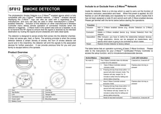
  • 1. Include to or Exclude from a Z-WaveTM Network SF812 SMOKE DETECTOR Inside the detector, there is a link key which is used to carry out the function of inclusion, exclusion, association and reset. When first power is applied, its LED flashes on and off alternately and repeatedly for 4 minutes, which implies that it has not been assigned a node ID and cannot work with Z-Wave enabled devices. Please get familiar with the terms below before starting the operations. The photoelectric Smoke Detector is a Z-WaveTM enabled device which is fully compatible with any Z-WaveTM enabled network. Z-WaveTM enabled devices displaying the Z-WaveTM logo can also be used with it regardless of the manufacturer, and ours can also be used in other manufacturer’s Z-WaveTM enabled networks. Inclusion of this detector on other manufacturer’s Wireless Controller menu allows remote operation of connected modules when the detector is triggered. Z-Wave node in the system also acts as a repeater, so as to re-transmit the RF signal to ensure that the signal is received by its intended destination by routing the signal around obstacles and radio dead spots. Function Inclusion Exclusion The detector is designed to sense smoke that comes into the detector chamber. It does not sense gas, heat, or flame. The working principle is when the smoke detector detects a certain density of smoke, the horn of smoke detector will sound and in the meantime, the detector will emit the signals to the associated devices for further execution. It can provide precious time for you and your family to escape before a fire spreads. Association Reset Description Add a Z-Wave enabled device (e.g. Smoke Detector) to Z-Wave network. Delete a Z-Wave enabled device (e.g. Smoke Detector) from the network. After inclusion, you have to define the relationship between devices. Trough association, device can be assigned as master/slave, and specify which slave is going to be controlled by which master. Restore Smoke Detector to factory default. The table below lists an operation summary of basic Z-Wave functions. Please refer to the instructions for your Z-WaveTM Certificated Primary Controller to access the setup function, and to include/exclude/associate devices. Product Overview 5 Action/Status 4 Description Link LED Indication No node ID The Z-Wave Controller does not allocate 2-second on, 2-second off 6 a node ID to the detector. 1. 2. Have Z-Wave Controller entered Flashes when link key is inclusion mode. Inclusion pressed Pressing link key three times within 1.5 second will enter inclusion mode. The Detector will stay “awake” for 10 minutes to allow time for setting and device status enquiring. 1. 2. Flashes when link key is exclusion mode. Exclusion Have Z-Wave Controller entered pressed Pressing link key three times within 1.5 second will enter exclusion mode. Horn Test Button LED Connector’s Hole Cover Latch Battery Cover Link Key Connector Tamper Switch Link LED Mounting Bracket The Detector will stay “awake” for 10 minutes to allow time for setting and device status enquiring. Node ID has been excluded. 1 2-second on, 2-second off
  • 2. Action/Status Description Link LED Indication 1. Pressing link key three times within 1.5 Flashes when link key is second will enter exclusion mode pressed 2. Within 1 second, press link key again LED is on for 5 seconds 3. Node ID is excluded, and it sets the Reset FIGURE 1 Locations for placing smoke detectors for single residence with only one sleeping area. and hold it until LED is off 2-second on, 2-second off device back to factory default state. 1. Have Z-Wave Controller entered Flashes when link key is association mode. Association pressed 2. Pressing link key 3 times within 1.5 3. Refer to group support as described second will enter association mode FIGURE 2 Locations for placing smoke detectors for single-floor residence with more than one sleeping area. on page 5 Failed or success in including/excluding the node ID can be viewed from the Z-Wave Controller. Choosing a Mounting Location The detector is designed for use in a single residential unit only, such as a single family home or apartment. It is not meant to be used in lobbies, hallways, basements, or another apartment in multi-family buildings, unless there are already working detectors in each family unit. Smoke detectors, placed in common areas outside of the individual living unit, such as on porches or in hallways, may not provide early warning to residents. In multi-family buildings, each family living unit should set up its own detectors. 2. Install a detector on every floor of a multi-floor home or apartment as shown in FIGURE 3. FIGURE 3 Locations for placing smoke detectors for a multi-floor residence. The detector is not meant to be used in non-residential buildings. Warehouses, industrial or commercial buildings, and special purpose non-residential buildings require special fire detection and alarm systems. This detector is not a suitable substitute for complete fire detection systems for places where many people live or work, such as hotels or motels. The same is true of dormitories, hospitals, nursing homes or group homes of any kind, even if they were once single family homes. 3. Install a minimum of two detectors in any household. 4. Install a detector inside every bedroom. 5. Install smoke detectors at both ends of a bedroom hallway if the hallway is more than 40 feet (12 meters) long. 6. Install a detector inside every room where one sleeps with the door partly or completely closed, since smoke could be blocked by the closed door and a hallway alarm may not wake up the sleeper if the door is closed. 7. Install detectors as close to the center of the ceiling as possible. If this is not practical, put the detector on the ceiling, no closer than 4 inches (10 cm) from any wall or corner as shown in FIGURE 4. For complete coverage in residential units, it should be installed in all rooms, halls, storage areas, basements and attics in each family living unit. Minimum coverage is one detector on each floor and one in each sleeping area. Useful tips are listed hereunder: 1. Install a detector in the hallway outside every separate bedroom area as shown in FIGURE 1. Two detectors are required in homes with two bedroom areas as shown in FIGURE 2. 2
  • 3. distance is not possible, e.g. in a mobile home, try to install the detector as far away from the combustion particles as possible, preferably on the wall. To prevent nuisance alarms, provide good ventilation in such places. IMPORTANT: For any reason, do not disable the detector to avoid nuisance alarms. FIGURE 4 Recommended best and acceptable locations to mount smoke detectors. 3. When air streams passing by kitchens, the way how a detector can sense combustion particles in normal air-flow paths is graphically shown in FIGURE 6, which indicates the correct and incorrect smoke detector locations concerning this problem. 8. If ceiling mounting is not possible, put wall-mounted detectors between 4 and 6 inches (10~15 cm) from the ceiling (FIGURE 4). 9. If some of your rooms have sloped, peaked, or gabled ceilings, try to mount detectors 3 feet (0.9 meter) measured horizontally from the highest point of the ceiling as shown in FIGURE 5. FIGURE 6 Recommended smoke detector locations to avoid air streams with combustion particles. FIGURE 5 Recommended location to mount smoke detectors in rooms with sloped, gabled or peaked ceiling. 4. In damp or very humid areas, or near bathrooms with showers. Moisture in humid air can enter the sensing chamber, then turns into droplets upon cooling, which can cause nuisance alarms. Install detectors at least 10 feet (3 meters) away from bathrooms. 5. In very cold or very hot areas, including unheated buildings or outdoor rooms. If the temperature goes above or below the operating range of smoke detector, it will not work properly. The temperature range for your smoke detector is 4°C to 38°C (40°F to 100°F). 6. In very dusty or dirty areas, dirt and dust can build up on the detector’s sensing chamber, to make it overly sensitive. Additionally, dust or dirt can block openings to the sensing chamber and keep the detector from sensing smoke. 7. Near fresh air vents or very drafty areas like air conditioners, heaters or fans, fresh air vents and drafts can drive smoke away from smoke detectors. 8. Dead air spaces are often at the top of a peaked roof, or in the corners between ceilings and walls. Dead air may prevent smoke from reaching a detector. Refer to FIGURE 4 and 5 for recommended mounting locations. 9. In insect-infested areas, it is probable that the insects may enter a detector’s Locations Not To Install the Detector Nuisance alarms take place when smoke detectors are installed where they will not work properly. To avoid nuisance alarms, do not install smoke detectors in the following situations: 1. Combustion particles are the by-products of something that is burning. Thus, in or near areas where combustion particles are present you do not install the smoke detectors to avoid nuisance alarms, such as kitchens with few windows or poor ventilation, garages where there may be vehicle exhaust, near furnaces, hot water heaters, and space heaters. 2. Do not install smoke detectors less than 20 feet (6 meters) away from places where combustion particles are normally present, like kitchens. If a 20-foot 3
  • 4. sensing chamber to cause a nuisance alarm. Where bugs are a problem, please get rid of them before putting up a detector. 10. Near fluorescent lights, electrical “noise” from fluorescent lights may cause nuisance alarms. Install smoke detectors at least 5 feet (1.5 meters) away from such lights. WARNING: Never remove batteries to stop a nuisance alarm. Cooking smoke or a dusty furnace, sometimes called “friendly fires” can cause the alarm to sound. If this happens, open a window or fan the air around the detector to get rid of the smoke or dust. The alarm will turn itself off when the smoke is gone. If nuisance alarms persist, attempt to clean the detector as described in this Manual. FIGURE 8 FIGURE 9 8. The steps to open the battery cover and to install the battery are listed as follows: a. To power the detector requires a 9V alkaline battery. b. Open the battery cover and connect the battery with +ve and –ve in the correct position. Push battery firmly in until it snaps and cannot be shaken loose. NOTE: It comes with cover latches that will prevent the battery cover from closing if battery is not installed. (FIGURE 9) This tells you that the smoke detector will not work until a new battery is properly installed. c. Place the connector to the connector hole. Ensure that the direction of connector is inserted correctly according to the sticker affixed on the detector. (FIGURE 10) WARNING: Do not stand close to the detector when the alarm is sounding. The alarm is loud in order to wake you in an emergency. Too much exposure to the horn at close range may be harmful to your hearing. Installation 1. At the place where you are going to install the detector, draw a horizontal line six inches long. 2. Remove the mounting bracket from the detector by rotating it counterclockwise. (FIGURE 7) FIGURE 7 3. Place the bracket so that the two longest hole slots are aligned on the line. In each of keyhole slots, draw a mark to locate a mounting plug and screw. 4. Remove the bracket. 5. Using a 3/16-inch (5mm) drill bit, drills two holes at the marks and insert plastic wall plugs. Put the detector away from getting plaster dust on it when you drill holes for mounting. 6. Using the two screws and plastic wall plugs (all supplied), attach the bracket to the wall. 7. Line up the slot of the bracket and the detector. Push the detector onto the mounting bracket and turn it clockwise to fix it into place. (FIGURE 8) Pull outward on the detector to make sure it is securely attached to the mounting bracket. FIGURE 10 Operation 1. The detector sounds as long as the test button is pressed for 3 seconds or there is smoke in the detector. When the detector goes off, always check carefully to see that there is no fire and never remove the battery from the detector except when changing it! 2. Always test the detector immediately after returning from holiday, after a longer period of absence or periodically to ensure the detector funtions normally. Under the test button, there is a red control LED which flashes once every 30 4
  • 5. SENSOR_ALARM_REPORT seconds. It indicates the detector is under normal operation. When Smoke Detector senses smoke and simultaneously sounds an audible alarm, the red LED will flash frequently, once 0.67 seconds. If the detector does not sound when testing, the battery must be replaced. Event Present: [Command Class Sensor Alarm, Sensor Alarm Report, Sensor Type Smoke Alarm State = 255 (0 x FF), Seconds = 0x00] WARNING: Never use an open flame to test your detector. You may set fire to damage the detector, as well as your home. Event Clear: [Command Class Sensor Alarm, Sensor Alarm Report, Sensor Type Smoke Alarm State = 0, Seconds = 0x00] WARNING: When you are not testing the unit and the alarm horn sounds a loud continuous sound, this means the detector has sensed smoke or combustion particles in the air. Be sure that the alarm horn is a warning of a possible serious situation, which requires your immediate attention. 1.3 Tamper Trigger Report When the tamper is triggered (that is, the detector is opened with tamper switch being released), the detector will emit ALARM_REPORT command to the nodes of Grouping 1. Programming ALARM_REPORT Command: [Command Class Alarm, Alarm Type = 0x01, Alarm Level = 17(0x11)] 1. Z-Wave’s Group (Association Command Class Version 2) The Smoke Detector supports one association group with five nodes. This has the effect that when the detector is triggered, all devices associated with the detector will receive the relevant reports. There are two main kinds of reports: ALARM_REPORT and SENSOR_ALARM_REPORT. Please refer to the sections below for more details on the reports that the detector will emit when event occurs. Note: If you press test button under low battery status while tamper switch is released, the status LED will flash once. 1.4 Low Battery Report When the battery level of the detector drops to an unacceptable level, the detector will sound once every 30 seconds and send BATTERY_REPORT command to the nodes of Grouping 1 once per hour. 1.1 POWER_APPLIED command The Smoke Detector will send ALARM_REPORT command to the nodes of Grouping 1 to inform the devices that the detector is powered up. BATTERY_REPORT Command: [Command Class Alarm, Alarm Type = 0x01, Alarm Level = 255(0xFF)] ALARM_REPORT Command: [Command Class Alarm, Alarm Type = 0x02, Alarm Level = 0x01] The users can also enquire the battery status of the detector by sending BATTERY_ GET command via controller, however, this procedure can only be done during 5-second time allowance after the tamper switch/detector being triggered or 10 minutes wakeup time when power is first applied. Once the detector receives the command, it will return BATTERY_REPORT command. 1.2 Smoke Event Report Once the detector has been triggered by smoke, the detector will send SENSOR_ALARM_REPORT (Sensor State = 0xFF) to the nodes of Grouping 1 to inform them there is a smoke event; wait till the smoke is discharged, SENSOR_ALARM_REPORT (Sensor State = 0x00) will be sent to the associated devices. BATTERY_REPORT Command: [Command Class Battery, Battery Report, Battery Level = 20%-100%] If it displays with a message of “Battery Level = 255 (0xFF)”, it implies that the detector is at low battery status. Please replace the batteries as soon as possible. 5
  • 6. Specifications 2. Command Classes The Smoke Detector supports Command Classes including… Operating Frequency * COMMAND_CLASS_BATTERY * COMMAND_CLASS_VERISON * COMMAND_CLASS_SENSOR_ALARM * COMMAND_CLASS_ASSOCIATION_V2 * COMMAND_CLASS_MANUFACTURER_SPECIFIC 868.42 MHz (SF812-1) / 908.42 MHz (SF812-2) Battery Type 9V alkaline battery x 1 Operating Range Up to 30 meters line of sight (indoor) ZDK Version V5.02 *Specifications are subject to change without notice A501111353R01 Maintenance The smoke detector is preferably powered by a 9V alkaline battery which under normal conditions will have typical life in excess of 1 year. Replace the battery once a year. When changing the battery, clean and vacuum the dust off the detector’s sensing chamber carefully using a soft brush. Federal Communication Commission Interference Statement This equipment has been tested and found to comply with the limits for a Class B digital device, pursuant to Part 15 of the FCC Rules. These limits are designed to provide reasonable protection against harmful interference in a residential installation. This equipment generates, uses and can radiate radio frequency energy and, if not installed and used in accordance with the instructions, may cause harmful interference to radio communications. However, there is no guarantee that interference will not occur in a particular installation. If this equipment does cause harmful interference to radio or television reception, which can be determined by turning the equipment off and on, the user is encouraged to try to correct the interference by one of the following measures: Troubleshooting Symptom Possible Cause Recommendation LED not illuminating, the detector not working Run out of battery power; check if reverse battery polarity Check if the detector is our of order Replace a new battery LED cannot be displayed and the detector not working when pressing the test button The detector does not stay awake for 10 minutes when power is first supplied Reverse battery polarity or poor battery connections Run out of battery power Button pressing time is not long enough; it should be pressed and held for more than 1 second Check if detector is out of order Do not open the detector; send it to the local retailer. Refit the battery with correct polarity - Replace a new battery Press and hold the button for longer than 1 second Reorient or relocate the receiving antenna. Increase the separation between the equipment and receiver. Connect the equipment into an outlet on a circuit different from that to which the receiver is connected. Consult the dealer or an experienced radio/TV technician for help. This device complies with Part 15 of the FCC Rules. Operation is subject to the following two conditions: (1) This device may not cause harmful interference, and (2) this device must accept any interference received, including interference that may cause undesired operation. Remove the battery, press link key several times to release the existing battery power and wait for approx.10 seconds before replacing the battery. FCC Caution: Any changes or modifications not expressly approved by the party responsible for compliance could void the user's authority to operate this equipment. This transmitter must not be co-located or operating in conjunction with any other antenna or transmitter. 6
  • 7. WARNING: Do not dispose of electrical appliances as unsorted municipal waste, use separate collection facilities. Contact your local government for information regarding the collection systems available. If electrical appliances are disposed of in landfills or dumps, hazardous substances can leak into the groundwater and get into the food chain, damaging your health and well-being. When replacing old appliances with new once, the retailer is legally obligated to take back your old appliance for disposal at least for free of charge. 7