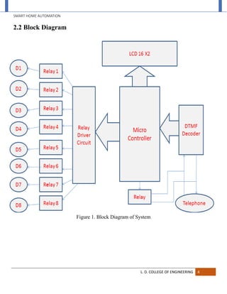
SMART HOME AUTOMATION
Project Guide:
Prof. S. K. Rana
Assistant Professor,
Electronics & Communication Engg Department,
L. D. College of Engineering,
Ahmedabad-3800015.
Prepared By:
Mitul Lakhani
Dhaval Sonani
Rahil Shah
SMART HOME AUTOMATION
L. D. COLLEGE OF ENGINEERING II
SMART HOME AUTOMATION USING MOBILE PHONE
A Project Report
Submitted by
Rahil Shah
Mitul Lakhani
Dhaval Sonani
In fulfillment for the award of the degree
of
BACHELOR OF ENGINEERING
in
Department of Electronics & Communication Engineering
L. D. College Of Engineering, Ahmedabad-380015
Gujarat Technological University, Ahmedabad
Approved by
Prof. S. K. Rana
Assistant Professor,
Electronics & Communication Engg. Department
May 2014
SMART HOME AUTOMATION
L. D. COLLEGE OF ENGINEERING III
L. D. College Of Engineering
Electronics & Communication Engineering Department
2013-14
Certificate
Date:
This is to certify that the dissertation entitled “SMART HOME AUTOMATION
USING MOBILE PHONE” has been carried out by Rahil Shah (100280111046),
Mitulkumar Lakhani (100280111038), Dhaval Sonani (100280111026) under
my guidance in fulfillment of the degree of Bachelor of Engineering in Electronics
and Communication Engineering of Gujarat Technological University, Ahmedabad
during the academic year 2013-14.
------------------------------- ----------------------------------
Project Guide Examiner
Prof. S. K. Rana
Assistant Professor,
Electronics & Communication Engg. Department
L. D. College of Engineering, Ahmedabad
---------------------------------------
Head of Department
Prof. A. B. Nandurbarkar
Electronics & Communication Engg. Department
L. D. College of Engineering, Ahmedabad
SMART HOME AUTOMATION
L. D. COLLEGE OF ENGINEERING IV
ACKNOWLEDGEMENT
“Perseverance, inspiration and motivation have always played a key role in any venture. It is
not just the brain that matters most, but that which guides them. The character, the heart,
generous qualities and progressive forces. What was conceived just as an idea materialized
slowly into concrete facts. The metamorphosis took endless hours of toil, had its moments of
frustration, but in the end everything seemed to have sense”.
At this level of understanding it is often difficult to understand the wide spectrum of knowledge
without proper guidance and advice. Hence, we take this opportunity to express our heartfelt
gratitude to our project guide Prof. S. K. Rana who had faith in us and allowed us to work on
this project.
We would like to thanks all the faculty members for his immense interest, valuable guidance,
constant inspiration and kind co-operation throughout the period of word undertaken, which has
been instrumented in the success of our project.
We would like to pay our sincere gratitude to our respected Prof. A. B. Nandurbarkar (HOD,
EC Deptt) for providing us opportunity to work in computer lab as a part of the major part.
We also acknowledge our profound sense of gratitude to all the non teaching staff members of
our department who have been instrumental for providing us the instruments in laboratories and
moral support to complete the project.
We thank our friends and family for their moral support to carve out this project and above all
GOD for removing all hurdles in the way.
SMART HOME AUTOMATION
L. D. COLLEGE OF ENGINEERING V
Abstract
The home automation becomes important, because it gives the user the comfortable and
easily for using the home devices. The implementation and design of wireless home automation
control used two methods, WLAN technology and RF remote control handheld to control of the
selective home devices with integral security and protected system. The system is low cost and
flexible with the increasing variety of devices to be controlled.
The objective of this project is to enable users to remotely control their home appliances
and systems using a cell phone-based interface. To access the control unit, the user should send
an authentication code along with the required/desired function/action to his/her home control
system via GSM. Upon being properly authenticated, the cell phone-based interface at home
(control unit) would relay the commands to a microcontroller that would perform the required
function/action.
SMART HOME AUTOMATION
L. D. COLLEGE OF ENGINEERING VI
LIST OF FIGURES
Figure Page
01. Block Diagram of System 4
02. Circuit Diagram of the System 7
03. Block Diagram of AT89S52 11
04. Pin Diagram of AT89S52 12
05. Block Diagram of MT8870D 18
06. Pin Diagram of MT8870D 18
07. LCD Display 21
08. Relay 24
09. SPDT Relay 24
10. Pin Diagram of MCT2E 25
11. Connection Diagram of MT8870D 30
12. Splitter 31
13. Connection of splitter with landline and system 32
SMART HOME AUTOMATION
L. D. COLLEGE OF ENGINEERING VII
TABLE OF CONTENTS
Acknowledgement IV
Abstract V
List of Figures VI
Table of Contents VII
Chapter 1: Introduction 1
1.1 Problem statement
1.2 Operating environment
1.3 Assumptions
1.4 Review of related literature
1.5 Present scenario
1.6 Present and Future scope
Chapter 2: System Information 3
2.1 System Specifications
2.2 Block Diagram
2.3 Block Diagram description
2.4 System Flowchart
SMART HOME AUTOMATION
L. D. COLLEGE OF ENGINEERING VIII
Chapter 3: Working and Modules Details 8
3.1 System Working
3.2 System Schematic
3.3 Information of All The Circuit Components
3.3.1 Microcontroller AT89S52
3.3.2 DTMF decoder MT8870D
3.3.3 LCD 16X2 Module
3.3.4 Relay
3.3.5 MCT2E optpisolator
Chapter 4: About DTMF 27
4.1 What is DTMF code?
4.2 Transmission of DTMF code in GSM network
4.3 Decoding DTMF code
4.4 Connecting mobile phone with MT8870
4.5 Connection Diagram for MT8870
4.6 Splitter and Its Connection with Landline Phone
Chapter 5: Conclusion & Future Scope 33
5.1 Conclusion
5.2 Future Scope
References 34
SMART HOME AUTOMATION
L. D. COLLEGE OF ENGINEERING IX
Annexures 35
 OAPS report
 Undertaking about originality of work
 User utilization certificates of each team member
 User feedback certificates of each team member
 Completely filled and downloaded PDE report
 Online project report submission certificate
SMART HOME AUTOMATION
L. D. COLLEGE OF ENGINEERING 1
CHAPTER 1: Introduction
1.1 Problem Statement
The objective of this project is to develop a device that allows for a user to remotely
control and monitor multiple home appliances using a cellular phone. This system will be a
powerful and flexible tool that will offer this service at any time, and from anywhere with the
constraints of the technologies being applied. Possible target appliances include (but are not
limited to) climate control systems, security systems and lights; anything with an electrical
interface.
The proposed approach for designing this system is to implement a microcontroller based
control module that receives its instructions and commands from a cellular phone over the GSM
network. The microcontroller then will carry out the issued commands. For security purposes, a
means of identification and user authentication will be implemented, and will combine caller
identification with a password authorization.
1.2 Operating Environment
The control system will include two separate units: the cellular phone, and the control unit.
There will therefore be two operating environments. The cellular phone will operate indoors
and outdoors whereas the control unit will operate indoors.
SMART HOME AUTOMATION
L. D. COLLEGE OF ENGINEERING 2
1.3 Assumptions
The following is a list of assumptions for the project:
1. The user and control unit will establish communication via GSM.
2. All service charges from service provider apply.
3. The controlled appliances will have to have an electrical interface in order to be controlled
By microcontroller.
1.4 Review of related literature
This project has been made by several people, but no one has used DTMF technology for
controlling home appliances. They have used DTMF technology for different purposes but not
for controlling home appliances.
In our project we have used the auto answer facility which is present in many of the cell
phones today, so we escaped from designing the ring detector circuit.
1.5 Present Scenario
Possible customers for this product would be home improvement contractors, and supply
stores. The benefit of this is the end-product can be sold in large quantities and it can be
incorporated into the construction of modernize homes. The end-product will be not sold in
retails stores because reconfiguring of the end-product to control different electrical appliances
will be complicated and it should only be attempted by trained technicians. Retail stores would
also not be a good target for commercialization due to the system requiring a cellular phone
plan in order to operate. Advertising through cellular phone providers would be a more feasible
option.
SMART HOME AUTOMATION
L. D. COLLEGE OF ENGINEERING 3
CHAPTER 2: System Information
2.1 System Specifications
 An authenticated user can control eight home appliances from any remote place
having mobile phone network.
 Regulated power supply: 5V and 500ma.
 Relay: 230V AC
 The system requires two phones out of which the one present at the control unit has
to be a cell phone with auto answer facility.
 The system requires ATMEL microcontroller AT89S52 and DTMF decoder
MT8870D IC.
 It requires 16X2 LCD (Liquid Crystal Display) to display the device status.
SMART HOME AUTOMATION
L. D. COLLEGE OF ENGINEERING 4
2.2 Block Diagram
Figure 1. Block Diagram of System
SMART HOME AUTOMATION
L. D. COLLEGE OF ENGINEERING 5
2.3 Block Diagram Description
 Phone on the transmitting side:
The person who wants to switch on/off any device kept at the controller side calls
from a phone and, once the call gets picked up, enters the password and tones for a
corresponding device. Every key has to be pressed for a minimum amount of time to get
it latched at the decoder IC.
 Mobile phone on the receiving side:
The mobile phone on the receiver side picks up the phone automatically after
5seconds, and then makes the tones available to the DTMF tone decoder IC through the
headphone jack of the phone.
 DTMF Tone Decoder IC:
The DTMF tone decoder IC converts the received tones to their respective binary
values and then gives them as an input to the microcontroller.
The DTMF tone decoder IC’s internal architecture consists of a band split filter
section which separates the low and the high tone of the received tone pair, followed by a
digital decode(counting) section which verifies both the frequency and duration of the
received tones before passing resultant 4-bit code to the output bus. These 4-bits along
with a bit which validates a received tone are given as an input to the port1 of
microcontroller.
SMART HOME AUTOMATION
L. D. COLLEGE OF ENGINEERING 6
 The Microcontroller:
The five output bits of the decoder IC serve as an input to port 1 of the
microcontroller. Then each tone is verified by the programmed microcontroller and once
a correct sequence of code is received, output corresponding to the tones sent by the user
is made available at the port0, which is connected to relay through a relay driver.
 Relay Circuitry:
The output from the port0 of the microcontroller is given to the relay driver IC
which drives the corresponding relay, to which the home appliances are connected.
 Home Appliances:
One terminal of each appliance is connected to relay and the other terminal is
connected to 230v AC. As soon as the relay gets driven by the microcontroller the device
gets switched on/off.
SMART HOME AUTOMATION
L. D. COLLEGE OF ENGINEERING 7
2.4 System Flowchart:
SMART HOME AUTOMATION
L. D. COLLEGE OF ENGINEERING 8
Chapter 3: Working and Module Details:
3.1 System Working:
Home automation system automatically controls the home appliances when the
users are not able to access the devices physically. Microcontroller is the heart of the
system. The main technology used in the system is a DTMF (Dial Tone Multiple
Frequency). The system decodes the received code and gives the input to the
microcontroller. It generates the specific code according to saved program and controls
the connected home appliances. It also displays the device status on 16x2 LCD (Liquid
Crystal Display). Our system controls maximum eight devices. It is also possible to
connect more than eight devices. It is also possible to connect more than eight devices by
little modifications of the system.
In our system we have used AT89S52 microcontroller but it is also possible to use
another microcontroller. The working of DTMF decoder IC is explained in chapter 4 of
this report. We have used MCT2E optoisolator. It isolates the high voltage signal from the
sensitive system. So it prevents system damage. In the device driver circuit connection of
the two transistors provides current amplification. It is shown in the system schematic.
The diode connected parallel with the relay contacts provides a freewheeling of high
voltage. Hence it prevents the circuit from high voltage damage.
SMART HOME AUTOMATION
L. D. COLLEGE OF ENGINEERING 9
3.2 System Schematic:
Figure 2.Circuit Diagram of the System
SMART HOME AUTOMATION
L. D. COLLEGE OF ENGINEERING 10
3.3 Information of all the Circuit Components:
Microcontrotroller AT89S52
 Features:-
 Compatible with MCS-51® Products
 8K Bytes of In-System Programmable (ISP) Flash Memory
 Endurance: 1000 Write/Erase Cycles
 4.0V to 5.5V Operating Range
 Fully Static Operation: 0 Hz to 33 MHz
 Three-level Program Memory Lock
 256 x 8-bit Internal RAM
 32 Programmable I/O Lines
 Three 16-bit Timer/Counters
 Eight Interrupt Sources
 Full Duplex UART Serial Channel
 Low-power Idle and Power-down Modes
 Interrupt Recovery from Power-down Mode
 Watchdog Timer
 Dual Data Pointer
 Power-off Flag
 Fast Programming Time
 Flexible ISP Programming (Byte and Page Mode)
SMART HOME AUTOMATION
L. D. COLLEGE OF ENGINEERING 11
 Description:-
The AT89S52 is a low-power, high-performance CMOS 8-bit microcontroller with
8K bytes of in-system programmable Flash memory. The device is manufactured using
Atmel’s high-density nonvolatile memory technology and is compatible with the
industry-standard 80C51 instruction set and pin out. The on-chip Flash allows the
program memory to be reprogrammed in-system or by a conventional nonvolatile
memory programmer. By combining a versatile 8-bit CPU with in-system programmable
Flash on a monolithic chip, the Atmel AT89S52 is a powerful microcontroller which
provides a highly-flexible and cost-effective solution to many embedded control
applications.
The AT89S52 provides the following standard features: 8K bytes of Flash, 256
bytes of RAM, 32 I/O lines, Watchdog timer, two data pointers, three 16-bit
timer/counters, a six-vector two-level interrupt architecture, a full duplex serial port, on-
chip oscillator, and clock circuitry. In addition, the AT89S52 is designed with static logic
for operation down to zero frequency and supports two software selectable power saving
modes. The Idle Mode stops the CPU while allowing the RAM, timer/counters, serial
port, and interrupt system to continue functioning. The Power-down mode saves the
RAM contents but freezes the oscillator, disabling all other chip functions until the next
interrupt or hardware reset.
SMART HOME AUTOMATION
L. D. COLLEGE OF ENGINEERING 12
 Block Diagram:-
Figure 3. Block Diagram of AT89S52
SMART HOME AUTOMATION
L. D. COLLEGE OF ENGINEERING 13
 Pin Configuration:-
Figure 4. Pin Diagram of AT89S52
SMART HOME AUTOMATION
L. D. COLLEGE OF ENGINEERING 14
 Pin Description:-
VCC Supply voltage.
GND Ground.
Port 0 Port 0 is an 8-bit open drain bidirectional I/O port. As an output
port, each pin can sink eight TTL inputs. When 1s are written to port 0
pins, the pins can be used as high impedance inputs.
Port 0 can also be configured to be the multiplexed low-order
address/data bus during accesses to external program and data
memory.
In this mode, P0 has internal pull-ups. Port 0 also receives the code
bytes during Flash programming and outputs the code bytes during
program verification. External pull-ups are required during program
verification.
Port 1 Port 1 is an 8-bit bidirectional I/O port with internal pull-ups.
The Port 1 output buffers can sink/source four TTL inputs. When 1s
are written to Port 1 pins, they are pulled high by the internal pull-ups
and can be used as inputs.
As inputs, Port 1 pins that are externally being pulled low will source
current (IIL) because of the internal pull-ups. In addition, P1.0 and
P1.1 can be configured to be the timer/counter 2 external count input
(P1.0/T2) and the timer/counter 2 trigger input (P1.1/T2EX),
respectively, as shown in the following table. Port 1 also receives the
low-order address bytes during Flash Programming and verification.
SMART HOME AUTOMATION
L. D. COLLEGE OF ENGINEERING 15
Port 2 Port 2 is an 8-bit bidirectional I/O port with internal pull-ups. The Port
2 output buffers can sink/source four TTL inputs. When 1s are written to
Port 2 pins, they are pulled high by the internal pull-ups and can be used as
inputs. As inputs, Port 2 pins that are externally being pulled low will source
current (IIL) because of the internal pull-ups.
Port 2 emits the high-order address byte during fetches from external
program memory and during accesses to external data memory that use 16-
bit addresses (MOVX @DPTR).
In this application, Port 2 uses strong internal pull-ups when emitting 1s.
During accesses to external data memory that use 8-bit addresses (MOVX @
RI), Port 2 emits the contents of the P2 Special Function Register.
Port 2 also receives the high-order address bits and some control signals
during Flash programming and verification.
Port 3 Port 3 is an 8-bit bidirectional I/O port with internal pull-ups. The Port
3 output buffers can sink/source four TTL inputs. When 1s are written to
Port 3 pins, they are pulled high by the internal pull-ups and can be used as
inputs. As inputs, Port 3 pins that are externally being pulled low will source
current (IIL) because of the pull-ups.
SMART HOME AUTOMATION
L. D. COLLEGE OF ENGINEERING 16
Port 3 receives some control signals for Flash programming and verification.
Port 3 also serves the functions of various special features of the AT89S52,
as shown in the following table.
RST Reset input. A high on this pin for two machine cycles while
the oscillator is running resets the device. This pin drives high for 98
oscillator periods after the Watchdog times out. The DISRTO bit in
SFR AUXR (address 8EH) can be used to disable this feature. In the
default state of bit DISRTO, the RESET HIGH out feature is enabled.
ALE/PROG Address Latch Enable (ALE) is an output pulse for
latching the low byte of the address during accesses to external
memory. This pin is also the program pulse input (PROG) during
Flash programming. In normal operation, ALE is emitted at a constant
rate of 1/6 the oscillator frequency and may be used for external
timing or clocking purposes. Note, however, that one ALE pulse is
skipped during each access to external data memory. If desired, ALE
SMART HOME AUTOMATION
L. D. COLLEGE OF ENGINEERING 17
operation can be disabled by setting bit 0 of SFR location 8EH. With
the bit set, ALE is active only during a MOVX or MOVC instruction.
Otherwise, the pin is weakly pulled high. Setting the ALE-disable bit
has no effect if the microcontroller is in external execution mode.
PSEN Program Store Enable (PSEN) is the read strobe to external
program memory. When the AT89S52 is executing code from
external program memory, PSEN is activated twice each machine
cycle, except that two PSEN activations are skipped during each
access to external data memory.
EA/VPP External Access Enable. EA must be strapped to GND in order
to enable the device to fetch code from external program memory
locations starting at 0000H up to FFFFH.
Note, however, that if lock bit 1 is programmed, EA will be internally
latched on reset. EA should be strapped to VCC for internal program
executions. This pin also receives the 12-volt programming enable
voltage (VPP) during Flash programming.
XTAL1 Input to the inverting oscillator amplifier and input to the
internal clock operating circuit.
XTAL2 Output from the inverting oscillator amplifier.
SMART HOME AUTOMATION
L. D. COLLEGE OF ENGINEERING 18
DTMF Decoder MT8870D
Description:-
The is a complete DTMF receiver integrating both the band split filter
and digital decoder functions. The filter section uses switched capacitor techniques for
high and low group filters; the decoder uses digital counting techniques to detect and
decode all 16 DTMF tone pairs into a 4-bit code. External component count is minimized
by on chip provision of a differential input amplifier, clock oscillator and latched three-
state bus interface.
 Features:-
 Complete DTMF Receiver
 Low power consumption
 Internal gain setting amplifier
 Adjustable guard time
 Central office quality
 Power-down mode
 Inhibit mode
 Backward compatible with MT8870C/MT8870C-1
 Application:-
 Receiver system for British Telecom (BT) or CEPT Spec (MT8870D-1)
Paging systems Repeater systems/mobile radio Credit card systems Remote
control Personal computers Telephone answering machine.
 Chip Power Bias IN GS Dial Tone Filter.
 High Group Filter Zero Crossing Detectors Low Group Filter.
SMART HOME AUTOMATION
L. D. COLLEGE OF ENGINEERING 19
 Block Diagram:-
Figure 5. Block Diagram of MT8870D
 Pin Diagram:-

Figure 6. Pin Diagram of MT8870D
SMART HOME AUTOMATION
L. D. COLLEGE OF ENGINEERING 20
 Pin Description of MT8870D:-
SMART HOME AUTOMATION
L. D. COLLEGE OF ENGINEERING 21
LCD 16X 2 Modules
 Description:-
A liquid crystal display (LCD) is a thin, flat electronic visual display that uses the
light modulating properties of liquid crystals (LCs). LCs does not emit light directly.
They are used in a wide range of applications, including computer
monitors, television, instrument panels, aircraft cockpit displays, signage, etc. They are
common in consumer devices such as video players, gaming devices, clocks, watches,
calculators, and telephones. LCDs have displaced cathode ray tube (CRT) displays in
most applications. They are usually more compact, lightweight, portable, less expensive,
more reliable, and easier on the eyes. They are available in a wider range of screen sizes
than CRT and plasma displays, and since they do not use phosphors, they cannot suffer
image burn-in.
LCDs are more energy efficient and offer safer disposal than CRTs. Its low
electrical power consumption enables it to be used in battery-
powered electronic equipment. It is an electronically-modulated optical device made up
of any number of pixels filled with liquid crystals and arrayed in front of a light
source (backlight) or reflector to produce images in color or monochrome. The earliest
discovery leading to the development of LCD technology, the discovery of liquid
crystals, dates from 1888. By 2008, worldwide sales of televisions with LCD screens had
surpassed the sale of CRT units.
SMART HOME AUTOMATION
L. D. COLLEGE OF ENGINEERING 22
 Features:-
 It can be used to display corresponding characters in ASCII code.
 The module will automatically convert and display the data according to its
data type.
 255 steps backlight control.
 For continuous inputs, the module will carriage return automatically.
 Cursor position assignment and Tab function with configurable Tab steps
and HOME function.
 Destructive backspace, clear to end of line or end of screen from the cursor
position.
 Set the user defined characters to display various creative characters.
 Display off command to reduce power consumption.
 Pin Diagram:-
Figure 7. LCD Display
SMART HOME AUTOMATION
L. D. COLLEGE OF ENGINEERING 23
Pin Description:-
SMART HOME AUTOMATION
L. D. COLLEGE OF ENGINEERING 24
Relay
Description:-
A relay is an electrically operated switch. Many relays use
an electromagnet to operate a switching mechanism mechanically, but other
operating principles are also used. Relays are used where it is necessary to
control a circuit by a low-power signal (with complete electrical isolation
between control and controlled circuits), or where several circuits must be
controlled by one signal.
 Operation:-
A simple electromagnetic relay consists of a coil of wire wrapped
around a soft ironcore, an iron yoke which provides a low reluctance path
for magnetic flux, a movable iron armature, and one or more sets of contacts
(there are two in the relay pictured).
The armature is hinged to the yoke and mechanically linked to one or
more sets of moving contacts. It is held in place by a spring so that when the
relay is de-energized there is an air gap in the magnetic circuit. In this
condition, one of the two sets of contacts in the relay pictured is closed, and
the other set is open.
Other relays may have more or fewer sets of contacts depending on
their function. The relay in the picture also has a wire connecting the
armature to the yoke.
SMART HOME AUTOMATION
L. D. COLLEGE OF ENGINEERING 25
This ensures continuity of the circuit between the moving contacts on
the armature, and the circuit track on the printed circuit board (PCB) via the
yoke, which is soldered to the PCB.
When an electric current is passed through the coil it generates a magnetic
field that activates the armature and the consequent movement of the
movable contact either makes or breaks (depending upon construction) a
connection with a fixed contact.
If the set of contacts was closed when the relay was de-energized,
then the movement opens the contacts and breaks the connection, and vice
versa if the contacts were open. When the current to the coil is switched off,
the armature is returned by a force, approximately half as strong as the
magnetic force, to its relaxed position.
Figure 8. Relay Figure 9. SPDT Relay
SMART HOME AUTOMATION
L. D. COLLEGE OF ENGINEERING 26
MCT2E Optoisolator
 Features:-
 2500 or 1500 V Isolation.
 High DC Current Transfer Ratio.
 Low Cost Dual-In-Line Package.
 Description:-
The MCT2E, MCT2 are optically coupled isolators consisting of a Gallium
Arsenide infrared emitting diode and an NPN silicon phototransistor
mounted in a standard 6-pin dual-in-line package. Surface Mount Option
Available.
All electrical parameters are 100% tested by manufacturing. Specifications
are guaranteed to a cumulative 0.65% AQL.
 Pin Diagram:-
Figure 10. Pin Diagram of MCT2E
SMART HOME AUTOMATION
L. D. COLLEGE OF ENGINEERING 27
CHAPTER 4: About DTMF
4.1 DTMF (Dial Tone Multiple Frequency)
DTMF stands for dual tone multiple frequency. DTMF is a term which used in
telephone industry. When any key on telephone or mobile phone is pressed one tone is
generated and it is audible which nothing but a DTMF tone is to decode DTMF tone
from mobile phone we need MT8870 DTMF decoder IC, 3.5mm male and female
connector.
SMART HOME AUTOMATION
L. D. COLLEGE OF ENGINEERING 28
4.2 What is DTMF code?
When any of the key like "1", "2", "*", "#" etc is pressed particular code is
transmitted. This code is consisting of two frequencies among which one is higher
frequency and second one is lower frequency. Following table shows the combination of
frequency for respected keys.
According to above table "8" is combination of lower frequency of 852 Hz and higher
frequency of 1336 Hz and "#" is of lower frequency of 941 Hz and higher frequency of
1447 Hz. So this is all about DTMF code, now let see about how DTMF code are
generated, transmitted and Decoded in mobile phone system. Here i am only talk about
GSM system.
SMART HOME AUTOMATION
L. D. COLLEGE OF ENGINEERING 29
4.3 Transmission of DTMF code in GSM network
In GSM networks so many channels are available but mainly there is only two
channels...
1) Physical Channels
2) Logical Channels
DTMF code are transmitted in FACCH i.e. fast associated control channel. Complete
hierarchy of FACCH is given below
FACCH is a bidirectional channel i.e. uplink and downlink. It is used to transmit and
receive emergency controlling signal messages. When any data or message need to be
transmitted through this channel, it will replace the voice signal to digital signalling data
for very short amount of time.
SMART HOME AUTOMATION
L. D. COLLEGE OF ENGINEERING 30
4.4 Decoding DTMF code
When any DTMF code has been received at mobile phone it can be audible
through speaker. So to decode this DTMF code speaker output it self can be used. Output
of speaker is connected to IC MT8870 which is DTMF decoder IC. It used widely to
decode DTMF code. It gives 4-bit digital output q1, q2, q3, and q4 according to the
received key. Following table shows the equivalent digital output for each key.
SMART HOME AUTOMATION
L. D. COLLEGE OF ENGINEERING 31
4.5 Connection Diagram
Figure 11. Connection Diagram of MT8870D
SMART HOME AUTOMATION
L. D. COLLEGE OF ENGINEERING 32
4.6 Splitter and Its Connection with Landline Phone
Splitter is used to split the single line into two separate lines. It is same as the
device that we use for landline.
Figure 12. Splitter
Figure 13. Connection of splitter with landline and system
SMART HOME AUTOMATION
L. D. COLLEGE OF ENGINEERING 33
CHAPTER 5: Conclusion & Future Scope
5.1 Conclusion
The project has been developed by integrating features of all the hardware components
used. Presence of every module has been reasoned out and placed carefully thus contributing to
the best working of the unit. Using highly advanced IC’s and with the help of growing
technology the project has been successfully implemented. Finally we conclude that “HOME
AUTOMATION” is an emerging field and there is a huge scope for research and development.
5.2 Future Scope
This product is aimed toward average consumers who wish to control household
appliances remotely from their cell phones provided that the appliances are electrically
controllable. Example of feasible appliances and applications under consideration include;
enable/disable security systems, fans, lights, kitchen appliances, and heating/ventilation/air
conditioning system.
Right now we have designed the project for control of eight devices but it can be
designed for more number of devices. It can be further expanded with a voice interactive system
facility. A feedback system can also be included which provides the state of a device (whether it
is on/off) to the remote user.
SMART HOME AUTOMATION
L. D. COLLEGE OF ENGINEERING 34
References
Books
1. The 8051 Microcontroller And Embedded Systems Using Assembly And C, 2/E By Muhammad
Ali Mazidi
2. The 8051 Microcontroller By Kenneth J. Ayala
3. The essential guide to telecommunications By Annabel Z. Dodd
4. Power Supply Devices and Systems of Relay Protection By Valadimir Gurevich
Web References
www.atmel.in
www.motorola.com
www.engineersgarage.com
www.fadooengineers.com
www.buildcircuit.com
www.controlanything.com
www.circuitstoday.com
UNDERTAKING ABOUT ORIGINALITY OF WORK
We hereby certify that we are the sole authors of this IDP/UDP project report and that neither any part of this
IDP/UDP project report nor the whole of the IDP/UDP Project report has been submitted for a degree by other
student(s) to any other University or Institution.
We certify that, to the best of our knowledge, the current IDP/UDP Project report does not infringe upon anyone’s
copyright nor violate any proprietary rights and that any ideas, techniques, quotations or any other material from the
work of other people included in our IDP/UDP Project report, published or otherwise, are fully acknowledged in
accordance with the standard referencing practices. Furthermore, to the extent that we have included copyrighted
material that surpasses the boundary of fair dealing within the meaning of the Indian Copyright (Amendment) Act
2012, we certify that we have obtained a written permission from the copyright owner(s) to include such material(s)
in the current IDP/UDP Project report and have included copies of such copyright clearances to our appendix.
We have checked the write up of the present IDP/UDP Project report using anti-plagiarism database and it is in the
allowable limit. In case of any complaints pertaining to plagiarism, we certify that we shall be solely responsible for
the same and we understand that as per norms, University can even revoke BE degree conferred upon the student(s)
submitting this IDP/UDP Project report, in case it is found to be plagiarized.
Team:
Enrollment Number Name Signature
100280111038 LAKHANI
MITULKUMAR
LABHUBHAI
100280111026 SONANI DHAVAL
VINODBHAI
100280111046 SHAH RAHIL
PARESHBHAI
Place:Ahmedabad Date:2/5/14
Prof. S. K. Rana
Name of Guide Signature of Guide
GOVERNMENT OF GUJARAT
L. D. COLLEGE OF ENGINEERING, AHMEDABAD-380015.
Phone: 26306752(Office), 26302887 (Principal)
Fax : 079-26302887
MAY 02, 2014
USER UTILIZATION CERTIFICATE
NAME OF THE STUDENT: SHAH RAHIL PARESHBHAI
ENROLLMENT NUMBER: 100280111046
TITLE OF THE PROJECT: SMART HOME AUTOMATION
NAME OF THE GUIDE : PROF. S. K. RANA
TEAM ID : 130007605
1. QUALITY OF PROJECT WORK :
2. INNOVATIVE IDEA SUGGESTED/IMPLEMENTED :
3. USED IN INDUSTRY/BY OTHER USER:
4. WORK THAT CAN BE USED IN FEATURE:
PROF. S. K. RANA/EXTERNAL GUIDE
(E.C. DEPT., L.D.C.E.)
GOVERNMENT OF GUJARAT
L. D. COLLEGE OF ENGINEERING, AHMEDABAD-380015.
Phone: 26306752(Office), 26302887 (Principal)
Fax : 079-26302887
MAY 02, 2014
USER UTILIZATION CERTIFICATE
NAME OF THE STUDENT: LAKHANI MITULKUMAR LABHUBHAI
ENROLLMENT NUMBER: 100280111038
TITLE OF THE PROJECT: SMART HOME AUTOMATION
NAME OF THE GUIDE : PROF. S. K. RANA
TEAM ID :130007605
1. QUALITY OF PROJECT WORK :
2. INNOVATIVE IDEA SUGGESTED/IMPLEMENTED :
3. USED IN INDUSTRY/BY OTHER USER:
4. WORK THAT CAN BE USED IN FEATURE:
PROF. S. K. RANA/EXTERNAL GUIDE
(E.C. DEPT., L.D.C.E.)
GOVERNMENT OF GUJARAT
L. D. COLLEGE OF ENGINEERING, AHMEDABAD-380015.
Phone: 26306752(Office), 26302887 (Principal)
Fax : 079-26302887
MAY 02, 2014
USER UTILIZATION CERTIFICATE
NAME OF THE STUDENT: SONANI DHAVAL VINODBHAI
ENROLLMENT NUMBER: 100280111026
TITLE OF THE PROJECT: SMART HOME AUTOMATION
NAME OF THE GUIDE : PROF. S. K. RANA
TEAM ID : 130007605
1. QUALITY OF PROJECT WORK :
2. INNOVATIVE IDEA SUGGESTED/IMPLEMENTED :
3. USED IN INDUSTRY/BY OTHER USER:
4. WORK THAT CAN BE USED IN FEATURE:
PROF. S. K. RANA/EXTERNAL GUIDE
(E.C. DEPT., L.D.C.E.)
GOVERNMENT OF GUJARAT
L. D. COLLEGE OF ENGINEERING, AHMEDABAD-380015.
Phone: 26306752(Office), 26302887 (Principal)
Fax : 079-26302887
MAY 02, 2014
USER FEEDBACK CERTIFICATE
NAME OF THE STUDENT:LAKHANI MITULKUMAR LABHUBHAI
ENROLLMENT NUMBER:100280111038
TITLE OF THE PROJECT:SMART HOME AUTOMATION
NAME OF THE GUIDE : PROF. S. K. RANA
TEAM ID : 130007605
PROFICIENCY SHOWN BY THE STUDENT
1. ATTENDANCE :
2. CONDUCT :
3. THOROUGH LITERATURE STUDY DONE :
4. PRACTICAL ABILITY :
5. OBJECTIVES ACHIEVED :
INTERNAL/EXTERNAL GUIDE
(E.C. DEPT., L.D.C.E.)
GOVERNMENT OF GUJARAT
L. D. COLLEGE OF ENGINEERING, AHMEDABAD-380015.
Phone: 26306752(Office), 26302887 (Principal)
Fax : 079-26302887
MAY 02, 2014
USER FEEDBACK CERTIFICATE
NAME OF THE STUDENT:SONANI DHAVAL VINODBHAI
ENROLLMENT NUMBER:100280111026
TITLE OF THE PROJECT:SMART HOME AUTOMATION
NAME OF THE GUIDE : PROF. S. K. RANA
TEAM ID : 130007605
PROFICIENCY SHOWN BY THE STUDENT
1. ATTENDANCE :
2. CONDUCT :
3. THOROUGH LITERATURE STUDY DONE :
4. PRACTICAL ABILITY :
5. OBJECTIVES ACHIEVED :
INTERNAL/EXTERNAL GUIDE
(E.C. DEPT., L.D.C.E.)
GOVERNMENT OF GUJARAT
L. D. COLLEGE OF ENGINEERING, AHMEDABAD-380015.
Phone: 26306752(Office), 26302887 (Principal)
Fax : 079-26302887
MAY 02, 2014
USER FEEDBACK CERTIFICATE
NAME OF THE STUDENT:SHAH RAHIL PARESHBHAI
ENROLLMENT NUMBER:100280111046
TITLE OF THE PROJECT:SMART HOME AUTOMATION
NAME OF THE GUIDE : PROF. S. K. RANA
TEAM ID : 130007605
PROFICIENCY SHOWN BY THE STUDENT
1. ATTENDANCE :
2. CONDUCT :
3. THOROUGH LITERATURE STUDY DONE :
4. PRACTICAL ABILITY :
5. OBJECTIVES ACHIEVED :
INTERNAL/EXTERNAL GUIDE
(E.C. DEPT., L.D.C.E.)
GIC Patent Drafting Exercise 569Project Team:
(FOR OFFICE USE ONLY)
Application No:
Filing Date:
Amount of Fee paid:
CBR No:
FORM 1
THE PATENTS ACT 1970
(39 OF 1970)
&
THE PATENTS RULES, 2003
APPLICATION FOR GRANT OF PATENT
691
1. APPLICANT(S)
AddressID Email AddressMobile No.NationalityName
LAKHANI MITULKUMAR
LABHUBHAI
Indian 9998593726 lml.mitul@gmail.com1 B 408, GANGA
RESIDENCY, CAUSEWAY
CHAR RASTA,
SINGANPORE,
SURAT-395004
SHAH RAHIL
PARESHBHAI
Indian 9173985057 rpshah09@hotmail.com2 82,PRASAD
SOCIETY,OPP. INOX,
MAKTAMPUR ROAD,
BHARUCH-392012
SONANI DHAVAL
VINODBHAI
Indian 9173380390 dhavalsonani2921@gmail.co
m
3 RAMAN PARK, NAVO
MAHOLLO,
SINGANPORE,
SURAT-395004
2. INVENTOR(S)
NOTE: This is just a mock Patent Drafting Exercise (PDE) for semester 8, BE students of GTU. These documents are not to be submitted
with any patent office.
Page 1 of 5
GIC Patent Drafting Exercise 569Project Team:
Email AddressMobile No.AddressNationalityNameID
1 LAKHANI MITULKUMAR LABHUBHAIIndian B 408, GANGA
RESIDENCY,
CAUSEWAY CHAR
RASTA, SINGANPORE,
SURAT-395004
9998593726 lml.mitul@gmail.com
2 SHAH RAHIL PARESHBHAIIndian 82,PRASAD
SOCIETY,OPP. INOX,
MAKTAMPUR ROAD,
BHARUCH-392012
9173985057 rpshah09@hotmail.com
3 SONANI DHAVAL VINODBHAIIndian RAMAN PARK, NAVO
MAHOLLO,
SINGANPORE,
SURAT-395004
9173380390 dhavalsonani2921@gmail.co
m
3. TITLE OF INVENTION / PROJECT
SMART HOME AUTOMATION USING MOBILE
4. ADDRESS FOR CORRESPONDENCE OF APPLICANT/AUTHORIZED PATENT AGENT IN INDIA
NA
NA
Name:
Address:
Mobile: NA
NAEmail ID:
NOTE: This is just a mock Patent Drafting Exercise (PDE) for semester 8, BE students of GTU. These documents are not to be submitted
with any patent office.
Page 2 of 5
GIC Patent Drafting Exercise 569Project Team:
5. PRIORITY PARTICULARS OF THE APPLICATION(S) FIELD IN CONVENTION COUNTRY
6. PARTICULARS FOR FILING PATENT COOPERATION TREATY (PCT) NATIONAL PHASE
APPLICATION
7. PARTICULARS FOR FILING DIVISIONAL APPLICATION
8. PARTICULARS FOR FILING PATENT OF ADDITION
Country Application No. Filing Date Name of the Applicant Title of the Invention
N/A N/A N/A N/A N/A
International application number International filing date as alloted by the receiving office
N/A N/A
Main Application / Patent Number
Original(First) Application Number Date of filing of Original (first) application
Date of filing of main application
N/A N/A
N/A N/A
9. DECLARATIONS:
(i) Declaration by the inventor(s)
I/We, the above named inventor(s) is/are true & first inventor(s) for this invention and declare that the applicant(s)
herein is/are my/our assignee or legal representative.
Date: 29-April-2014
Name Sign & Date
LAKHANI MITULKUMAR
LABHUBHAI
1
SHAH RAHIL PARESHBHAI2
SONANI DHAVAL VINODBHAI3
(ii) Declaration by the applicant(s) in the convention country
I/We, the applicant (s) in the convention country declare that the applicant(s) herein is/are my/our
assignee or legal representative.
Not Applicable
NOTE: This is just a mock Patent Drafting Exercise (PDE) for semester 8, BE students of GTU. These documents are not to be submitted
with any patent office.
Page 3 of 5
GIC Patent Drafting Exercise 569Project Team:
The said invention is an improvement in or modification of the invention particulars of which are given in para 8.
The application is divided out of my/our application(s) particulars of which are given in para 7 and pray that this
application may be treated as deemed to have been filed on ___________under section 16 of the Act.
My/Our application in India is based on international application under Patent Cooperation Treaty (PCT) as
mentioned in para 6.
I/we claim the priority from the above mentioned applications(s) filed in the convention country/countries & state
that no application for protection in respect of invention had been made in a convention country before that date
by me/us or by any person from which I/we derived the title.
The application or each of the application,particulars of each are given in the para 5 was the first application in
the convention country/countries in respect of my/our invention.
I am/we are the assignee or the legal representative of true & first inventors.
There is no lawful ground of objection to the grant of the patent to me/us.
The invention as disclosed in the specification uses the biological material from India and the necessary
permission from the competent authority shall be submitted by me/us before the grant of patent to me/us.
The provisional specification relating to the invention is filed with this application.
I am/We are in possession of the above mentioned invention.
I/We, the applicant(s) hereby declare(s) that:-
(iii) Declaration by the applicant(s)
NOTE: This is just a mock Patent Drafting Exercise (PDE) for semester 8, BE students of GTU. These documents are not to be submitted
with any patent office.
Page 4 of 5
GIC Patent Drafting Exercise 569Project Team:
10. FOLLOWING ARE THE ATTACHMENTS WITH THE APPLICATION:
(j) ........................................
Fees Rs.XXX in Cash/Cheque/Bank Draft bearing No.XXX Date: XXX on XXX Bank.
I/We hereby declare that to the best of my /our knowledge, information and belief the fact and mtters stated
herein are correct and I/We request that a patent may be granted to me/us for the said invention.
Dated this ........ day of .......... 20.......
(a) Provisional specification/Complete specification
(b) Complete specification(In confirmation with the international application) / as amended before the
international.Preliminary Examination Authority(IPEA),as applicable(2 copies),No.of pages.....No.of claims.....
(c) Drawings(In confirmation with the international application)/as amended before the international Preliminary
Examination Authority(IPEA),as applicable(2 copies),No.of sheets.....
(d) Priority documents
(e) Translations of priority documents/specification/international search reports
(f) Statement and undertaking on Form 3
(g) Power of Authority
(h) Declaration of inventorship on Form 5
(i) Sequence listing in electronic Form
Sign & DateName
LAKHANI MITULKUMAR
LABHUBHAI
1
SHAH RAHIL PARESHBHAI2
SONANI DHAVAL VINODBHAI3
To
The Controller of Patent
The Patent Office, at Mumbai.
NOTE: This is just a mock Patent Drafting Exercise (PDE) for semester 8, BE students of GTU. These documents are not to be submitted
with any patent office.
Page 5 of 5
GIC Patent Drafting Exercise 569Project Team:
FORM 2
THE PATENTS ACT, 1970
(39 OF 1970)
&
THE PATENTS RULES, 2003
PROVISIONAL SPECIFICATION
1. TITLE OF INVENTION / PROJECT
SMART HOME AUTOMATION USING MOBILE
2. APPLICANT(S)
LAKHANI MITULKUMAR LABHUBHAI (Indian )
B 408, GANGA RESIDENCY, CAUSEWAY CHAR RASTA, SINGANPORE, SURAT-395004
SHAH RAHIL PARESHBHAI (Indian )
82,PRASAD SOCIETY,OPP. INOX, MAKTAMPUR ROAD, BHARUCH-392012
SONANI DHAVAL VINODBHAI (Indian )
RAMAN PARK, NAVO MAHOLLO, SINGANPORE, SURAT-395004
3. PREAMBLE TO THE DESCRIPTION
The following specification describes the invention.
NOTE: This is just a mock Patent Drafting Exercise (PDE) for semester 8, BE students of GTU. These documents are not to be submitted
with any patent office.
Page 1 of 3
GIC Patent Drafting Exercise 569Project Team:
4. DESCRIPTION
a. Field of Application / Project / Invention
Home automation and security systems currently are controlled by equipment installed at a customer
b. Prior Art / Background of the Invention / References
The control system will include two separate units: the cellular phone, and the control unit. There will therefore be two
operating environments. The cellular phone will operate indoors and outdoors whereas the control unit will operate
indoors.
c. Summary of the Invention/Project
The project has been developed by integrating features of all the hardware components used. Presence of every module
has been reasoned out and placed carefully thus contributing to the best working of the unit. Using highly advanced IC’
s and with the help of growing technology the project has been successfully implemented. Finally we conclude that
“HOME AUTOMATION” is an emerging field and there is a huge scope for research and development .
d. Objects of the Invention/Project
System and method for home automation and security
e. Drawing(s)
f. Description of the Invention
A home automation and security system is provided in which a home automation and security controller in a
customer premises is coupled with a remotely located central control facility using a continuous connectivity
access line providing a data channel separate from a voice channel. The controller at the customer premises is
responsible for monitoring and applying control signals to devices in the home and for supporting a human
interface. The remotely located central control facility is responsible for providing the computational and
database resources to the controller.
g. Examples
home automation system using an infrared (IR)/radio frequency (RF) integration remote control module
based on a network.
h. Unique Features of the Project
20
5. DATE & SIGNATURE
29-April-2014Date:
Sign & DateName
LAKHANI MITULKUMAR
LABHUBHAI
1
SHAH RAHIL PARESHBHAI2
SONANI DHAVAL VINODBHAI3
NOTE: This is just a mock Patent Drafting Exercise (PDE) for semester 8, BE students of GTU. These documents are not to be submitted
with any patent office.
Page 2 of 3
GIC Patent Drafting Exercise 569Project Team:
6. ABSTRACT OF THE INVENTION
The home automation becomes important, because it gives the user the comfortable and easily for using the home
devices. The implementation and design of wireless home automation control used two methods, WLAN technology and
RF remote control handheld to control of the selective home devices with integral security and protected system. The
system is low cost and flexible with the increasing variety of devices to be controlled.
NOTE: This is just a mock Patent Drafting Exercise (PDE) for semester 8, BE students of GTU. These documents are not to be submitted
with any patent office.
Page 3 of 3
GIC Patent Drafting Exercise 569Project Team:
NOTE: This is just a mock Patent Drafting Exercise (PDE) for semester 8, BE students of GTU. These documents are not to be submitted
with any patent office.
Page 1 of 1
GIC Patent Drafting Exercise 569Project Team:
FORM 3
THE PATENTS ACT, 1970
(39 OF 1970)
&
THE PATENTS RULES, 2003
STATEMENT AND UNDERTAKING UNDER SECTION 8
1. Declaration
I/We, LAKHANI MITULKUMAR LABHUBHAI
SHAH RAHIL PARESHBHAI
SONANI DHAVAL VINODBHAI
2. Name, Address and Nationality of the joint Applicant
LAKHANI MITULKUMAR LABHUBHAI (Indian )
B 408, GANGA RESIDENCY, CAUSEWAY CHAR RASTA, SINGANPORE, SURAT-395004
SHAH RAHIL PARESHBHAI (Indian )
82,PRASAD SOCIETY,OPP. INOX, MAKTAMPUR ROAD, BHARUCH-392012
SONANI DHAVAL VINODBHAI (Indian )
RAMAN PARK, NAVO MAHOLLO, SINGANPORE, SURAT-395004
(i) that I/We have not made any application for the same/substantially the same
invention outside India.
(ii) that the right in the application(s) has/have been assigned to,
hereby declare:
Name of the
Country
Date of
Application
Application
Number
Status of the
Application
Date of
Publication
Date of Grant
N/A N/A N/A N/A N/A N/A
(iii) that I/We undertake that up to the date of grant of patent by the Controller, I/We
would keep him inform in writing the details regarding corresponding application(s)
for patents filed outside India within 3 months from the date of filing of such
application.
Dated this _____________day of ___________ ,20____
3. Signature of Applicants
(Sign and Date)
LAKHANI MITULKUMAR
LABHUBHAI
(Sign and Date)
SHAH RAHIL PARESHBHAI
(Sign and Date)
SONANI DHAVAL
VINODBHAI
To
The Controller of Patent
The Patent Office, at Mumbai.
NOTE: This is just a mock Patent Drafting Exercise (PDE) for semester 8, BE students of GTU. These documents are not to be submitted
with any patent office.
Page 1 of 1
GUJARAT TECHNOLOGICAL UNIVERSITY
ONLINE PROJECT REPORT SUBMISSION CERTIFICATE
Date of Receipt: 4/29/2014 8:50:32AM _
This is to certify that, GTU has received the project report of
SHAH RAHIL PARESHBHAI, SONANI DHAVAL
VINODBHAI, LAKHANI MITULKUMAR LABHUBHAI
entitled on SMART HOME AUTOMATION USING MOBILE
from Electronics & Communication Engineering of L. D.
College Of Engineering, Ahmedabad
The Receipt No is: GTU/PT/2014/BE/569
Disclaimer:
This is a computer generated copy and does not indicate that your report has been evaluated. This is the receipt that
GTU has received a copy of the file that you have uploaded as your project report.

Smart Home Automation

  • 1.
    SMART HOME AUTOMATION ProjectGuide: Prof. S. K. Rana Assistant Professor, Electronics & Communication Engg Department, L. D. College of Engineering, Ahmedabad-3800015. Prepared By: Mitul Lakhani Dhaval Sonani Rahil Shah
  • 2.
    SMART HOME AUTOMATION L.D. COLLEGE OF ENGINEERING II SMART HOME AUTOMATION USING MOBILE PHONE A Project Report Submitted by Rahil Shah Mitul Lakhani Dhaval Sonani In fulfillment for the award of the degree of BACHELOR OF ENGINEERING in Department of Electronics & Communication Engineering L. D. College Of Engineering, Ahmedabad-380015 Gujarat Technological University, Ahmedabad Approved by Prof. S. K. Rana Assistant Professor, Electronics & Communication Engg. Department May 2014
  • 3.
    SMART HOME AUTOMATION L.D. COLLEGE OF ENGINEERING III L. D. College Of Engineering Electronics & Communication Engineering Department 2013-14 Certificate Date: This is to certify that the dissertation entitled “SMART HOME AUTOMATION USING MOBILE PHONE” has been carried out by Rahil Shah (100280111046), Mitulkumar Lakhani (100280111038), Dhaval Sonani (100280111026) under my guidance in fulfillment of the degree of Bachelor of Engineering in Electronics and Communication Engineering of Gujarat Technological University, Ahmedabad during the academic year 2013-14. ------------------------------- ---------------------------------- Project Guide Examiner Prof. S. K. Rana Assistant Professor, Electronics & Communication Engg. Department L. D. College of Engineering, Ahmedabad --------------------------------------- Head of Department Prof. A. B. Nandurbarkar Electronics & Communication Engg. Department L. D. College of Engineering, Ahmedabad
  • 4.
    SMART HOME AUTOMATION L.D. COLLEGE OF ENGINEERING IV ACKNOWLEDGEMENT “Perseverance, inspiration and motivation have always played a key role in any venture. It is not just the brain that matters most, but that which guides them. The character, the heart, generous qualities and progressive forces. What was conceived just as an idea materialized slowly into concrete facts. The metamorphosis took endless hours of toil, had its moments of frustration, but in the end everything seemed to have sense”. At this level of understanding it is often difficult to understand the wide spectrum of knowledge without proper guidance and advice. Hence, we take this opportunity to express our heartfelt gratitude to our project guide Prof. S. K. Rana who had faith in us and allowed us to work on this project. We would like to thanks all the faculty members for his immense interest, valuable guidance, constant inspiration and kind co-operation throughout the period of word undertaken, which has been instrumented in the success of our project. We would like to pay our sincere gratitude to our respected Prof. A. B. Nandurbarkar (HOD, EC Deptt) for providing us opportunity to work in computer lab as a part of the major part. We also acknowledge our profound sense of gratitude to all the non teaching staff members of our department who have been instrumental for providing us the instruments in laboratories and moral support to complete the project. We thank our friends and family for their moral support to carve out this project and above all GOD for removing all hurdles in the way.
  • 5.
    SMART HOME AUTOMATION L.D. COLLEGE OF ENGINEERING V Abstract The home automation becomes important, because it gives the user the comfortable and easily for using the home devices. The implementation and design of wireless home automation control used two methods, WLAN technology and RF remote control handheld to control of the selective home devices with integral security and protected system. The system is low cost and flexible with the increasing variety of devices to be controlled. The objective of this project is to enable users to remotely control their home appliances and systems using a cell phone-based interface. To access the control unit, the user should send an authentication code along with the required/desired function/action to his/her home control system via GSM. Upon being properly authenticated, the cell phone-based interface at home (control unit) would relay the commands to a microcontroller that would perform the required function/action.
  • 6.
    SMART HOME AUTOMATION L.D. COLLEGE OF ENGINEERING VI LIST OF FIGURES Figure Page 01. Block Diagram of System 4 02. Circuit Diagram of the System 7 03. Block Diagram of AT89S52 11 04. Pin Diagram of AT89S52 12 05. Block Diagram of MT8870D 18 06. Pin Diagram of MT8870D 18 07. LCD Display 21 08. Relay 24 09. SPDT Relay 24 10. Pin Diagram of MCT2E 25 11. Connection Diagram of MT8870D 30 12. Splitter 31 13. Connection of splitter with landline and system 32
  • 7.
    SMART HOME AUTOMATION L.D. COLLEGE OF ENGINEERING VII TABLE OF CONTENTS Acknowledgement IV Abstract V List of Figures VI Table of Contents VII Chapter 1: Introduction 1 1.1 Problem statement 1.2 Operating environment 1.3 Assumptions 1.4 Review of related literature 1.5 Present scenario 1.6 Present and Future scope Chapter 2: System Information 3 2.1 System Specifications 2.2 Block Diagram 2.3 Block Diagram description 2.4 System Flowchart
  • 8.
    SMART HOME AUTOMATION L.D. COLLEGE OF ENGINEERING VIII Chapter 3: Working and Modules Details 8 3.1 System Working 3.2 System Schematic 3.3 Information of All The Circuit Components 3.3.1 Microcontroller AT89S52 3.3.2 DTMF decoder MT8870D 3.3.3 LCD 16X2 Module 3.3.4 Relay 3.3.5 MCT2E optpisolator Chapter 4: About DTMF 27 4.1 What is DTMF code? 4.2 Transmission of DTMF code in GSM network 4.3 Decoding DTMF code 4.4 Connecting mobile phone with MT8870 4.5 Connection Diagram for MT8870 4.6 Splitter and Its Connection with Landline Phone Chapter 5: Conclusion & Future Scope 33 5.1 Conclusion 5.2 Future Scope References 34
  • 9.
    SMART HOME AUTOMATION L.D. COLLEGE OF ENGINEERING IX Annexures 35  OAPS report  Undertaking about originality of work  User utilization certificates of each team member  User feedback certificates of each team member  Completely filled and downloaded PDE report  Online project report submission certificate
  • 10.
    SMART HOME AUTOMATION L.D. COLLEGE OF ENGINEERING 1 CHAPTER 1: Introduction 1.1 Problem Statement The objective of this project is to develop a device that allows for a user to remotely control and monitor multiple home appliances using a cellular phone. This system will be a powerful and flexible tool that will offer this service at any time, and from anywhere with the constraints of the technologies being applied. Possible target appliances include (but are not limited to) climate control systems, security systems and lights; anything with an electrical interface. The proposed approach for designing this system is to implement a microcontroller based control module that receives its instructions and commands from a cellular phone over the GSM network. The microcontroller then will carry out the issued commands. For security purposes, a means of identification and user authentication will be implemented, and will combine caller identification with a password authorization. 1.2 Operating Environment The control system will include two separate units: the cellular phone, and the control unit. There will therefore be two operating environments. The cellular phone will operate indoors and outdoors whereas the control unit will operate indoors.
  • 11.
    SMART HOME AUTOMATION L.D. COLLEGE OF ENGINEERING 2 1.3 Assumptions The following is a list of assumptions for the project: 1. The user and control unit will establish communication via GSM. 2. All service charges from service provider apply. 3. The controlled appliances will have to have an electrical interface in order to be controlled By microcontroller. 1.4 Review of related literature This project has been made by several people, but no one has used DTMF technology for controlling home appliances. They have used DTMF technology for different purposes but not for controlling home appliances. In our project we have used the auto answer facility which is present in many of the cell phones today, so we escaped from designing the ring detector circuit. 1.5 Present Scenario Possible customers for this product would be home improvement contractors, and supply stores. The benefit of this is the end-product can be sold in large quantities and it can be incorporated into the construction of modernize homes. The end-product will be not sold in retails stores because reconfiguring of the end-product to control different electrical appliances will be complicated and it should only be attempted by trained technicians. Retail stores would also not be a good target for commercialization due to the system requiring a cellular phone plan in order to operate. Advertising through cellular phone providers would be a more feasible option.
  • 12.
    SMART HOME AUTOMATION L.D. COLLEGE OF ENGINEERING 3 CHAPTER 2: System Information 2.1 System Specifications  An authenticated user can control eight home appliances from any remote place having mobile phone network.  Regulated power supply: 5V and 500ma.  Relay: 230V AC  The system requires two phones out of which the one present at the control unit has to be a cell phone with auto answer facility.  The system requires ATMEL microcontroller AT89S52 and DTMF decoder MT8870D IC.  It requires 16X2 LCD (Liquid Crystal Display) to display the device status.
  • 13.
    SMART HOME AUTOMATION L.D. COLLEGE OF ENGINEERING 4 2.2 Block Diagram Figure 1. Block Diagram of System
  • 14.
    SMART HOME AUTOMATION L.D. COLLEGE OF ENGINEERING 5 2.3 Block Diagram Description  Phone on the transmitting side: The person who wants to switch on/off any device kept at the controller side calls from a phone and, once the call gets picked up, enters the password and tones for a corresponding device. Every key has to be pressed for a minimum amount of time to get it latched at the decoder IC.  Mobile phone on the receiving side: The mobile phone on the receiver side picks up the phone automatically after 5seconds, and then makes the tones available to the DTMF tone decoder IC through the headphone jack of the phone.  DTMF Tone Decoder IC: The DTMF tone decoder IC converts the received tones to their respective binary values and then gives them as an input to the microcontroller. The DTMF tone decoder IC’s internal architecture consists of a band split filter section which separates the low and the high tone of the received tone pair, followed by a digital decode(counting) section which verifies both the frequency and duration of the received tones before passing resultant 4-bit code to the output bus. These 4-bits along with a bit which validates a received tone are given as an input to the port1 of microcontroller.
  • 15.
    SMART HOME AUTOMATION L.D. COLLEGE OF ENGINEERING 6  The Microcontroller: The five output bits of the decoder IC serve as an input to port 1 of the microcontroller. Then each tone is verified by the programmed microcontroller and once a correct sequence of code is received, output corresponding to the tones sent by the user is made available at the port0, which is connected to relay through a relay driver.  Relay Circuitry: The output from the port0 of the microcontroller is given to the relay driver IC which drives the corresponding relay, to which the home appliances are connected.  Home Appliances: One terminal of each appliance is connected to relay and the other terminal is connected to 230v AC. As soon as the relay gets driven by the microcontroller the device gets switched on/off.
  • 16.
    SMART HOME AUTOMATION L.D. COLLEGE OF ENGINEERING 7 2.4 System Flowchart:
  • 17.
    SMART HOME AUTOMATION L.D. COLLEGE OF ENGINEERING 8 Chapter 3: Working and Module Details: 3.1 System Working: Home automation system automatically controls the home appliances when the users are not able to access the devices physically. Microcontroller is the heart of the system. The main technology used in the system is a DTMF (Dial Tone Multiple Frequency). The system decodes the received code and gives the input to the microcontroller. It generates the specific code according to saved program and controls the connected home appliances. It also displays the device status on 16x2 LCD (Liquid Crystal Display). Our system controls maximum eight devices. It is also possible to connect more than eight devices. It is also possible to connect more than eight devices by little modifications of the system. In our system we have used AT89S52 microcontroller but it is also possible to use another microcontroller. The working of DTMF decoder IC is explained in chapter 4 of this report. We have used MCT2E optoisolator. It isolates the high voltage signal from the sensitive system. So it prevents system damage. In the device driver circuit connection of the two transistors provides current amplification. It is shown in the system schematic. The diode connected parallel with the relay contacts provides a freewheeling of high voltage. Hence it prevents the circuit from high voltage damage.
  • 18.
    SMART HOME AUTOMATION L.D. COLLEGE OF ENGINEERING 9 3.2 System Schematic: Figure 2.Circuit Diagram of the System
  • 19.
    SMART HOME AUTOMATION L.D. COLLEGE OF ENGINEERING 10 3.3 Information of all the Circuit Components: Microcontrotroller AT89S52  Features:-  Compatible with MCS-51® Products  8K Bytes of In-System Programmable (ISP) Flash Memory  Endurance: 1000 Write/Erase Cycles  4.0V to 5.5V Operating Range  Fully Static Operation: 0 Hz to 33 MHz  Three-level Program Memory Lock  256 x 8-bit Internal RAM  32 Programmable I/O Lines  Three 16-bit Timer/Counters  Eight Interrupt Sources  Full Duplex UART Serial Channel  Low-power Idle and Power-down Modes  Interrupt Recovery from Power-down Mode  Watchdog Timer  Dual Data Pointer  Power-off Flag  Fast Programming Time  Flexible ISP Programming (Byte and Page Mode)
  • 20.
    SMART HOME AUTOMATION L.D. COLLEGE OF ENGINEERING 11  Description:- The AT89S52 is a low-power, high-performance CMOS 8-bit microcontroller with 8K bytes of in-system programmable Flash memory. The device is manufactured using Atmel’s high-density nonvolatile memory technology and is compatible with the industry-standard 80C51 instruction set and pin out. The on-chip Flash allows the program memory to be reprogrammed in-system or by a conventional nonvolatile memory programmer. By combining a versatile 8-bit CPU with in-system programmable Flash on a monolithic chip, the Atmel AT89S52 is a powerful microcontroller which provides a highly-flexible and cost-effective solution to many embedded control applications. The AT89S52 provides the following standard features: 8K bytes of Flash, 256 bytes of RAM, 32 I/O lines, Watchdog timer, two data pointers, three 16-bit timer/counters, a six-vector two-level interrupt architecture, a full duplex serial port, on- chip oscillator, and clock circuitry. In addition, the AT89S52 is designed with static logic for operation down to zero frequency and supports two software selectable power saving modes. The Idle Mode stops the CPU while allowing the RAM, timer/counters, serial port, and interrupt system to continue functioning. The Power-down mode saves the RAM contents but freezes the oscillator, disabling all other chip functions until the next interrupt or hardware reset.
  • 21.
    SMART HOME AUTOMATION L.D. COLLEGE OF ENGINEERING 12  Block Diagram:- Figure 3. Block Diagram of AT89S52
  • 22.
    SMART HOME AUTOMATION L.D. COLLEGE OF ENGINEERING 13  Pin Configuration:- Figure 4. Pin Diagram of AT89S52
  • 23.
    SMART HOME AUTOMATION L.D. COLLEGE OF ENGINEERING 14  Pin Description:- VCC Supply voltage. GND Ground. Port 0 Port 0 is an 8-bit open drain bidirectional I/O port. As an output port, each pin can sink eight TTL inputs. When 1s are written to port 0 pins, the pins can be used as high impedance inputs. Port 0 can also be configured to be the multiplexed low-order address/data bus during accesses to external program and data memory. In this mode, P0 has internal pull-ups. Port 0 also receives the code bytes during Flash programming and outputs the code bytes during program verification. External pull-ups are required during program verification. Port 1 Port 1 is an 8-bit bidirectional I/O port with internal pull-ups. The Port 1 output buffers can sink/source four TTL inputs. When 1s are written to Port 1 pins, they are pulled high by the internal pull-ups and can be used as inputs. As inputs, Port 1 pins that are externally being pulled low will source current (IIL) because of the internal pull-ups. In addition, P1.0 and P1.1 can be configured to be the timer/counter 2 external count input (P1.0/T2) and the timer/counter 2 trigger input (P1.1/T2EX), respectively, as shown in the following table. Port 1 also receives the low-order address bytes during Flash Programming and verification.
  • 24.
    SMART HOME AUTOMATION L.D. COLLEGE OF ENGINEERING 15 Port 2 Port 2 is an 8-bit bidirectional I/O port with internal pull-ups. The Port 2 output buffers can sink/source four TTL inputs. When 1s are written to Port 2 pins, they are pulled high by the internal pull-ups and can be used as inputs. As inputs, Port 2 pins that are externally being pulled low will source current (IIL) because of the internal pull-ups. Port 2 emits the high-order address byte during fetches from external program memory and during accesses to external data memory that use 16- bit addresses (MOVX @DPTR). In this application, Port 2 uses strong internal pull-ups when emitting 1s. During accesses to external data memory that use 8-bit addresses (MOVX @ RI), Port 2 emits the contents of the P2 Special Function Register. Port 2 also receives the high-order address bits and some control signals during Flash programming and verification. Port 3 Port 3 is an 8-bit bidirectional I/O port with internal pull-ups. The Port 3 output buffers can sink/source four TTL inputs. When 1s are written to Port 3 pins, they are pulled high by the internal pull-ups and can be used as inputs. As inputs, Port 3 pins that are externally being pulled low will source current (IIL) because of the pull-ups.
  • 25.
    SMART HOME AUTOMATION L.D. COLLEGE OF ENGINEERING 16 Port 3 receives some control signals for Flash programming and verification. Port 3 also serves the functions of various special features of the AT89S52, as shown in the following table. RST Reset input. A high on this pin for two machine cycles while the oscillator is running resets the device. This pin drives high for 98 oscillator periods after the Watchdog times out. The DISRTO bit in SFR AUXR (address 8EH) can be used to disable this feature. In the default state of bit DISRTO, the RESET HIGH out feature is enabled. ALE/PROG Address Latch Enable (ALE) is an output pulse for latching the low byte of the address during accesses to external memory. This pin is also the program pulse input (PROG) during Flash programming. In normal operation, ALE is emitted at a constant rate of 1/6 the oscillator frequency and may be used for external timing or clocking purposes. Note, however, that one ALE pulse is skipped during each access to external data memory. If desired, ALE
  • 26.
    SMART HOME AUTOMATION L.D. COLLEGE OF ENGINEERING 17 operation can be disabled by setting bit 0 of SFR location 8EH. With the bit set, ALE is active only during a MOVX or MOVC instruction. Otherwise, the pin is weakly pulled high. Setting the ALE-disable bit has no effect if the microcontroller is in external execution mode. PSEN Program Store Enable (PSEN) is the read strobe to external program memory. When the AT89S52 is executing code from external program memory, PSEN is activated twice each machine cycle, except that two PSEN activations are skipped during each access to external data memory. EA/VPP External Access Enable. EA must be strapped to GND in order to enable the device to fetch code from external program memory locations starting at 0000H up to FFFFH. Note, however, that if lock bit 1 is programmed, EA will be internally latched on reset. EA should be strapped to VCC for internal program executions. This pin also receives the 12-volt programming enable voltage (VPP) during Flash programming. XTAL1 Input to the inverting oscillator amplifier and input to the internal clock operating circuit. XTAL2 Output from the inverting oscillator amplifier.
  • 27.
    SMART HOME AUTOMATION L.D. COLLEGE OF ENGINEERING 18 DTMF Decoder MT8870D Description:- The is a complete DTMF receiver integrating both the band split filter and digital decoder functions. The filter section uses switched capacitor techniques for high and low group filters; the decoder uses digital counting techniques to detect and decode all 16 DTMF tone pairs into a 4-bit code. External component count is minimized by on chip provision of a differential input amplifier, clock oscillator and latched three- state bus interface.  Features:-  Complete DTMF Receiver  Low power consumption  Internal gain setting amplifier  Adjustable guard time  Central office quality  Power-down mode  Inhibit mode  Backward compatible with MT8870C/MT8870C-1  Application:-  Receiver system for British Telecom (BT) or CEPT Spec (MT8870D-1) Paging systems Repeater systems/mobile radio Credit card systems Remote control Personal computers Telephone answering machine.  Chip Power Bias IN GS Dial Tone Filter.  High Group Filter Zero Crossing Detectors Low Group Filter.
  • 28.
    SMART HOME AUTOMATION L.D. COLLEGE OF ENGINEERING 19  Block Diagram:- Figure 5. Block Diagram of MT8870D  Pin Diagram:-  Figure 6. Pin Diagram of MT8870D
  • 29.
    SMART HOME AUTOMATION L.D. COLLEGE OF ENGINEERING 20  Pin Description of MT8870D:-
  • 30.
    SMART HOME AUTOMATION L.D. COLLEGE OF ENGINEERING 21 LCD 16X 2 Modules  Description:- A liquid crystal display (LCD) is a thin, flat electronic visual display that uses the light modulating properties of liquid crystals (LCs). LCs does not emit light directly. They are used in a wide range of applications, including computer monitors, television, instrument panels, aircraft cockpit displays, signage, etc. They are common in consumer devices such as video players, gaming devices, clocks, watches, calculators, and telephones. LCDs have displaced cathode ray tube (CRT) displays in most applications. They are usually more compact, lightweight, portable, less expensive, more reliable, and easier on the eyes. They are available in a wider range of screen sizes than CRT and plasma displays, and since they do not use phosphors, they cannot suffer image burn-in. LCDs are more energy efficient and offer safer disposal than CRTs. Its low electrical power consumption enables it to be used in battery- powered electronic equipment. It is an electronically-modulated optical device made up of any number of pixels filled with liquid crystals and arrayed in front of a light source (backlight) or reflector to produce images in color or monochrome. The earliest discovery leading to the development of LCD technology, the discovery of liquid crystals, dates from 1888. By 2008, worldwide sales of televisions with LCD screens had surpassed the sale of CRT units.
  • 31.
    SMART HOME AUTOMATION L.D. COLLEGE OF ENGINEERING 22  Features:-  It can be used to display corresponding characters in ASCII code.  The module will automatically convert and display the data according to its data type.  255 steps backlight control.  For continuous inputs, the module will carriage return automatically.  Cursor position assignment and Tab function with configurable Tab steps and HOME function.  Destructive backspace, clear to end of line or end of screen from the cursor position.  Set the user defined characters to display various creative characters.  Display off command to reduce power consumption.  Pin Diagram:- Figure 7. LCD Display
  • 32.
    SMART HOME AUTOMATION L.D. COLLEGE OF ENGINEERING 23 Pin Description:-
  • 33.
    SMART HOME AUTOMATION L.D. COLLEGE OF ENGINEERING 24 Relay Description:- A relay is an electrically operated switch. Many relays use an electromagnet to operate a switching mechanism mechanically, but other operating principles are also used. Relays are used where it is necessary to control a circuit by a low-power signal (with complete electrical isolation between control and controlled circuits), or where several circuits must be controlled by one signal.  Operation:- A simple electromagnetic relay consists of a coil of wire wrapped around a soft ironcore, an iron yoke which provides a low reluctance path for magnetic flux, a movable iron armature, and one or more sets of contacts (there are two in the relay pictured). The armature is hinged to the yoke and mechanically linked to one or more sets of moving contacts. It is held in place by a spring so that when the relay is de-energized there is an air gap in the magnetic circuit. In this condition, one of the two sets of contacts in the relay pictured is closed, and the other set is open. Other relays may have more or fewer sets of contacts depending on their function. The relay in the picture also has a wire connecting the armature to the yoke.
  • 34.
    SMART HOME AUTOMATION L.D. COLLEGE OF ENGINEERING 25 This ensures continuity of the circuit between the moving contacts on the armature, and the circuit track on the printed circuit board (PCB) via the yoke, which is soldered to the PCB. When an electric current is passed through the coil it generates a magnetic field that activates the armature and the consequent movement of the movable contact either makes or breaks (depending upon construction) a connection with a fixed contact. If the set of contacts was closed when the relay was de-energized, then the movement opens the contacts and breaks the connection, and vice versa if the contacts were open. When the current to the coil is switched off, the armature is returned by a force, approximately half as strong as the magnetic force, to its relaxed position. Figure 8. Relay Figure 9. SPDT Relay
  • 35.
    SMART HOME AUTOMATION L.D. COLLEGE OF ENGINEERING 26 MCT2E Optoisolator  Features:-  2500 or 1500 V Isolation.  High DC Current Transfer Ratio.  Low Cost Dual-In-Line Package.  Description:- The MCT2E, MCT2 are optically coupled isolators consisting of a Gallium Arsenide infrared emitting diode and an NPN silicon phototransistor mounted in a standard 6-pin dual-in-line package. Surface Mount Option Available. All electrical parameters are 100% tested by manufacturing. Specifications are guaranteed to a cumulative 0.65% AQL.  Pin Diagram:- Figure 10. Pin Diagram of MCT2E
  • 36.
    SMART HOME AUTOMATION L.D. COLLEGE OF ENGINEERING 27 CHAPTER 4: About DTMF 4.1 DTMF (Dial Tone Multiple Frequency) DTMF stands for dual tone multiple frequency. DTMF is a term which used in telephone industry. When any key on telephone or mobile phone is pressed one tone is generated and it is audible which nothing but a DTMF tone is to decode DTMF tone from mobile phone we need MT8870 DTMF decoder IC, 3.5mm male and female connector.
  • 37.
    SMART HOME AUTOMATION L.D. COLLEGE OF ENGINEERING 28 4.2 What is DTMF code? When any of the key like "1", "2", "*", "#" etc is pressed particular code is transmitted. This code is consisting of two frequencies among which one is higher frequency and second one is lower frequency. Following table shows the combination of frequency for respected keys. According to above table "8" is combination of lower frequency of 852 Hz and higher frequency of 1336 Hz and "#" is of lower frequency of 941 Hz and higher frequency of 1447 Hz. So this is all about DTMF code, now let see about how DTMF code are generated, transmitted and Decoded in mobile phone system. Here i am only talk about GSM system.
  • 38.
    SMART HOME AUTOMATION L.D. COLLEGE OF ENGINEERING 29 4.3 Transmission of DTMF code in GSM network In GSM networks so many channels are available but mainly there is only two channels... 1) Physical Channels 2) Logical Channels DTMF code are transmitted in FACCH i.e. fast associated control channel. Complete hierarchy of FACCH is given below FACCH is a bidirectional channel i.e. uplink and downlink. It is used to transmit and receive emergency controlling signal messages. When any data or message need to be transmitted through this channel, it will replace the voice signal to digital signalling data for very short amount of time.
  • 39.
    SMART HOME AUTOMATION L.D. COLLEGE OF ENGINEERING 30 4.4 Decoding DTMF code When any DTMF code has been received at mobile phone it can be audible through speaker. So to decode this DTMF code speaker output it self can be used. Output of speaker is connected to IC MT8870 which is DTMF decoder IC. It used widely to decode DTMF code. It gives 4-bit digital output q1, q2, q3, and q4 according to the received key. Following table shows the equivalent digital output for each key.
  • 40.
    SMART HOME AUTOMATION L.D. COLLEGE OF ENGINEERING 31 4.5 Connection Diagram Figure 11. Connection Diagram of MT8870D
  • 41.
    SMART HOME AUTOMATION L.D. COLLEGE OF ENGINEERING 32 4.6 Splitter and Its Connection with Landline Phone Splitter is used to split the single line into two separate lines. It is same as the device that we use for landline. Figure 12. Splitter Figure 13. Connection of splitter with landline and system
  • 42.
    SMART HOME AUTOMATION L.D. COLLEGE OF ENGINEERING 33 CHAPTER 5: Conclusion & Future Scope 5.1 Conclusion The project has been developed by integrating features of all the hardware components used. Presence of every module has been reasoned out and placed carefully thus contributing to the best working of the unit. Using highly advanced IC’s and with the help of growing technology the project has been successfully implemented. Finally we conclude that “HOME AUTOMATION” is an emerging field and there is a huge scope for research and development. 5.2 Future Scope This product is aimed toward average consumers who wish to control household appliances remotely from their cell phones provided that the appliances are electrically controllable. Example of feasible appliances and applications under consideration include; enable/disable security systems, fans, lights, kitchen appliances, and heating/ventilation/air conditioning system. Right now we have designed the project for control of eight devices but it can be designed for more number of devices. It can be further expanded with a voice interactive system facility. A feedback system can also be included which provides the state of a device (whether it is on/off) to the remote user.
  • 43.
    SMART HOME AUTOMATION L.D. COLLEGE OF ENGINEERING 34 References Books 1. The 8051 Microcontroller And Embedded Systems Using Assembly And C, 2/E By Muhammad Ali Mazidi 2. The 8051 Microcontroller By Kenneth J. Ayala 3. The essential guide to telecommunications By Annabel Z. Dodd 4. Power Supply Devices and Systems of Relay Protection By Valadimir Gurevich Web References www.atmel.in www.motorola.com www.engineersgarage.com www.fadooengineers.com www.buildcircuit.com www.controlanything.com www.circuitstoday.com
  • 45.
    UNDERTAKING ABOUT ORIGINALITYOF WORK We hereby certify that we are the sole authors of this IDP/UDP project report and that neither any part of this IDP/UDP project report nor the whole of the IDP/UDP Project report has been submitted for a degree by other student(s) to any other University or Institution. We certify that, to the best of our knowledge, the current IDP/UDP Project report does not infringe upon anyone’s copyright nor violate any proprietary rights and that any ideas, techniques, quotations or any other material from the work of other people included in our IDP/UDP Project report, published or otherwise, are fully acknowledged in accordance with the standard referencing practices. Furthermore, to the extent that we have included copyrighted material that surpasses the boundary of fair dealing within the meaning of the Indian Copyright (Amendment) Act 2012, we certify that we have obtained a written permission from the copyright owner(s) to include such material(s) in the current IDP/UDP Project report and have included copies of such copyright clearances to our appendix. We have checked the write up of the present IDP/UDP Project report using anti-plagiarism database and it is in the allowable limit. In case of any complaints pertaining to plagiarism, we certify that we shall be solely responsible for the same and we understand that as per norms, University can even revoke BE degree conferred upon the student(s) submitting this IDP/UDP Project report, in case it is found to be plagiarized. Team: Enrollment Number Name Signature 100280111038 LAKHANI MITULKUMAR LABHUBHAI 100280111026 SONANI DHAVAL VINODBHAI 100280111046 SHAH RAHIL PARESHBHAI Place:Ahmedabad Date:2/5/14 Prof. S. K. Rana Name of Guide Signature of Guide
  • 46.
    GOVERNMENT OF GUJARAT L.D. COLLEGE OF ENGINEERING, AHMEDABAD-380015. Phone: 26306752(Office), 26302887 (Principal) Fax : 079-26302887 MAY 02, 2014 USER UTILIZATION CERTIFICATE NAME OF THE STUDENT: SHAH RAHIL PARESHBHAI ENROLLMENT NUMBER: 100280111046 TITLE OF THE PROJECT: SMART HOME AUTOMATION NAME OF THE GUIDE : PROF. S. K. RANA TEAM ID : 130007605 1. QUALITY OF PROJECT WORK : 2. INNOVATIVE IDEA SUGGESTED/IMPLEMENTED : 3. USED IN INDUSTRY/BY OTHER USER: 4. WORK THAT CAN BE USED IN FEATURE: PROF. S. K. RANA/EXTERNAL GUIDE (E.C. DEPT., L.D.C.E.)
  • 47.
    GOVERNMENT OF GUJARAT L.D. COLLEGE OF ENGINEERING, AHMEDABAD-380015. Phone: 26306752(Office), 26302887 (Principal) Fax : 079-26302887 MAY 02, 2014 USER UTILIZATION CERTIFICATE NAME OF THE STUDENT: LAKHANI MITULKUMAR LABHUBHAI ENROLLMENT NUMBER: 100280111038 TITLE OF THE PROJECT: SMART HOME AUTOMATION NAME OF THE GUIDE : PROF. S. K. RANA TEAM ID :130007605 1. QUALITY OF PROJECT WORK : 2. INNOVATIVE IDEA SUGGESTED/IMPLEMENTED : 3. USED IN INDUSTRY/BY OTHER USER: 4. WORK THAT CAN BE USED IN FEATURE: PROF. S. K. RANA/EXTERNAL GUIDE (E.C. DEPT., L.D.C.E.)
  • 48.
    GOVERNMENT OF GUJARAT L.D. COLLEGE OF ENGINEERING, AHMEDABAD-380015. Phone: 26306752(Office), 26302887 (Principal) Fax : 079-26302887 MAY 02, 2014 USER UTILIZATION CERTIFICATE NAME OF THE STUDENT: SONANI DHAVAL VINODBHAI ENROLLMENT NUMBER: 100280111026 TITLE OF THE PROJECT: SMART HOME AUTOMATION NAME OF THE GUIDE : PROF. S. K. RANA TEAM ID : 130007605 1. QUALITY OF PROJECT WORK : 2. INNOVATIVE IDEA SUGGESTED/IMPLEMENTED : 3. USED IN INDUSTRY/BY OTHER USER: 4. WORK THAT CAN BE USED IN FEATURE: PROF. S. K. RANA/EXTERNAL GUIDE (E.C. DEPT., L.D.C.E.)
  • 49.
    GOVERNMENT OF GUJARAT L.D. COLLEGE OF ENGINEERING, AHMEDABAD-380015. Phone: 26306752(Office), 26302887 (Principal) Fax : 079-26302887 MAY 02, 2014 USER FEEDBACK CERTIFICATE NAME OF THE STUDENT:LAKHANI MITULKUMAR LABHUBHAI ENROLLMENT NUMBER:100280111038 TITLE OF THE PROJECT:SMART HOME AUTOMATION NAME OF THE GUIDE : PROF. S. K. RANA TEAM ID : 130007605 PROFICIENCY SHOWN BY THE STUDENT 1. ATTENDANCE : 2. CONDUCT : 3. THOROUGH LITERATURE STUDY DONE : 4. PRACTICAL ABILITY : 5. OBJECTIVES ACHIEVED : INTERNAL/EXTERNAL GUIDE (E.C. DEPT., L.D.C.E.)
  • 50.
    GOVERNMENT OF GUJARAT L.D. COLLEGE OF ENGINEERING, AHMEDABAD-380015. Phone: 26306752(Office), 26302887 (Principal) Fax : 079-26302887 MAY 02, 2014 USER FEEDBACK CERTIFICATE NAME OF THE STUDENT:SONANI DHAVAL VINODBHAI ENROLLMENT NUMBER:100280111026 TITLE OF THE PROJECT:SMART HOME AUTOMATION NAME OF THE GUIDE : PROF. S. K. RANA TEAM ID : 130007605 PROFICIENCY SHOWN BY THE STUDENT 1. ATTENDANCE : 2. CONDUCT : 3. THOROUGH LITERATURE STUDY DONE : 4. PRACTICAL ABILITY : 5. OBJECTIVES ACHIEVED : INTERNAL/EXTERNAL GUIDE (E.C. DEPT., L.D.C.E.)
  • 51.
    GOVERNMENT OF GUJARAT L.D. COLLEGE OF ENGINEERING, AHMEDABAD-380015. Phone: 26306752(Office), 26302887 (Principal) Fax : 079-26302887 MAY 02, 2014 USER FEEDBACK CERTIFICATE NAME OF THE STUDENT:SHAH RAHIL PARESHBHAI ENROLLMENT NUMBER:100280111046 TITLE OF THE PROJECT:SMART HOME AUTOMATION NAME OF THE GUIDE : PROF. S. K. RANA TEAM ID : 130007605 PROFICIENCY SHOWN BY THE STUDENT 1. ATTENDANCE : 2. CONDUCT : 3. THOROUGH LITERATURE STUDY DONE : 4. PRACTICAL ABILITY : 5. OBJECTIVES ACHIEVED : INTERNAL/EXTERNAL GUIDE (E.C. DEPT., L.D.C.E.)
  • 52.
    GIC Patent DraftingExercise 569Project Team: (FOR OFFICE USE ONLY) Application No: Filing Date: Amount of Fee paid: CBR No: FORM 1 THE PATENTS ACT 1970 (39 OF 1970) & THE PATENTS RULES, 2003 APPLICATION FOR GRANT OF PATENT 691 1. APPLICANT(S) AddressID Email AddressMobile No.NationalityName LAKHANI MITULKUMAR LABHUBHAI Indian 9998593726 lml.mitul@gmail.com1 B 408, GANGA RESIDENCY, CAUSEWAY CHAR RASTA, SINGANPORE, SURAT-395004 SHAH RAHIL PARESHBHAI Indian 9173985057 rpshah09@hotmail.com2 82,PRASAD SOCIETY,OPP. INOX, MAKTAMPUR ROAD, BHARUCH-392012 SONANI DHAVAL VINODBHAI Indian 9173380390 dhavalsonani2921@gmail.co m 3 RAMAN PARK, NAVO MAHOLLO, SINGANPORE, SURAT-395004 2. INVENTOR(S) NOTE: This is just a mock Patent Drafting Exercise (PDE) for semester 8, BE students of GTU. These documents are not to be submitted with any patent office. Page 1 of 5
  • 53.
    GIC Patent DraftingExercise 569Project Team: Email AddressMobile No.AddressNationalityNameID 1 LAKHANI MITULKUMAR LABHUBHAIIndian B 408, GANGA RESIDENCY, CAUSEWAY CHAR RASTA, SINGANPORE, SURAT-395004 9998593726 lml.mitul@gmail.com 2 SHAH RAHIL PARESHBHAIIndian 82,PRASAD SOCIETY,OPP. INOX, MAKTAMPUR ROAD, BHARUCH-392012 9173985057 rpshah09@hotmail.com 3 SONANI DHAVAL VINODBHAIIndian RAMAN PARK, NAVO MAHOLLO, SINGANPORE, SURAT-395004 9173380390 dhavalsonani2921@gmail.co m 3. TITLE OF INVENTION / PROJECT SMART HOME AUTOMATION USING MOBILE 4. ADDRESS FOR CORRESPONDENCE OF APPLICANT/AUTHORIZED PATENT AGENT IN INDIA NA NA Name: Address: Mobile: NA NAEmail ID: NOTE: This is just a mock Patent Drafting Exercise (PDE) for semester 8, BE students of GTU. These documents are not to be submitted with any patent office. Page 2 of 5
  • 54.
    GIC Patent DraftingExercise 569Project Team: 5. PRIORITY PARTICULARS OF THE APPLICATION(S) FIELD IN CONVENTION COUNTRY 6. PARTICULARS FOR FILING PATENT COOPERATION TREATY (PCT) NATIONAL PHASE APPLICATION 7. PARTICULARS FOR FILING DIVISIONAL APPLICATION 8. PARTICULARS FOR FILING PATENT OF ADDITION Country Application No. Filing Date Name of the Applicant Title of the Invention N/A N/A N/A N/A N/A International application number International filing date as alloted by the receiving office N/A N/A Main Application / Patent Number Original(First) Application Number Date of filing of Original (first) application Date of filing of main application N/A N/A N/A N/A 9. DECLARATIONS: (i) Declaration by the inventor(s) I/We, the above named inventor(s) is/are true & first inventor(s) for this invention and declare that the applicant(s) herein is/are my/our assignee or legal representative. Date: 29-April-2014 Name Sign & Date LAKHANI MITULKUMAR LABHUBHAI 1 SHAH RAHIL PARESHBHAI2 SONANI DHAVAL VINODBHAI3 (ii) Declaration by the applicant(s) in the convention country I/We, the applicant (s) in the convention country declare that the applicant(s) herein is/are my/our assignee or legal representative. Not Applicable NOTE: This is just a mock Patent Drafting Exercise (PDE) for semester 8, BE students of GTU. These documents are not to be submitted with any patent office. Page 3 of 5
  • 55.
    GIC Patent DraftingExercise 569Project Team: The said invention is an improvement in or modification of the invention particulars of which are given in para 8. The application is divided out of my/our application(s) particulars of which are given in para 7 and pray that this application may be treated as deemed to have been filed on ___________under section 16 of the Act. My/Our application in India is based on international application under Patent Cooperation Treaty (PCT) as mentioned in para 6. I/we claim the priority from the above mentioned applications(s) filed in the convention country/countries & state that no application for protection in respect of invention had been made in a convention country before that date by me/us or by any person from which I/we derived the title. The application or each of the application,particulars of each are given in the para 5 was the first application in the convention country/countries in respect of my/our invention. I am/we are the assignee or the legal representative of true & first inventors. There is no lawful ground of objection to the grant of the patent to me/us. The invention as disclosed in the specification uses the biological material from India and the necessary permission from the competent authority shall be submitted by me/us before the grant of patent to me/us. The provisional specification relating to the invention is filed with this application. I am/We are in possession of the above mentioned invention. I/We, the applicant(s) hereby declare(s) that:- (iii) Declaration by the applicant(s) NOTE: This is just a mock Patent Drafting Exercise (PDE) for semester 8, BE students of GTU. These documents are not to be submitted with any patent office. Page 4 of 5
  • 56.
    GIC Patent DraftingExercise 569Project Team: 10. FOLLOWING ARE THE ATTACHMENTS WITH THE APPLICATION: (j) ........................................ Fees Rs.XXX in Cash/Cheque/Bank Draft bearing No.XXX Date: XXX on XXX Bank. I/We hereby declare that to the best of my /our knowledge, information and belief the fact and mtters stated herein are correct and I/We request that a patent may be granted to me/us for the said invention. Dated this ........ day of .......... 20....... (a) Provisional specification/Complete specification (b) Complete specification(In confirmation with the international application) / as amended before the international.Preliminary Examination Authority(IPEA),as applicable(2 copies),No.of pages.....No.of claims..... (c) Drawings(In confirmation with the international application)/as amended before the international Preliminary Examination Authority(IPEA),as applicable(2 copies),No.of sheets..... (d) Priority documents (e) Translations of priority documents/specification/international search reports (f) Statement and undertaking on Form 3 (g) Power of Authority (h) Declaration of inventorship on Form 5 (i) Sequence listing in electronic Form Sign & DateName LAKHANI MITULKUMAR LABHUBHAI 1 SHAH RAHIL PARESHBHAI2 SONANI DHAVAL VINODBHAI3 To The Controller of Patent The Patent Office, at Mumbai. NOTE: This is just a mock Patent Drafting Exercise (PDE) for semester 8, BE students of GTU. These documents are not to be submitted with any patent office. Page 5 of 5
  • 57.
    GIC Patent DraftingExercise 569Project Team: FORM 2 THE PATENTS ACT, 1970 (39 OF 1970) & THE PATENTS RULES, 2003 PROVISIONAL SPECIFICATION 1. TITLE OF INVENTION / PROJECT SMART HOME AUTOMATION USING MOBILE 2. APPLICANT(S) LAKHANI MITULKUMAR LABHUBHAI (Indian ) B 408, GANGA RESIDENCY, CAUSEWAY CHAR RASTA, SINGANPORE, SURAT-395004 SHAH RAHIL PARESHBHAI (Indian ) 82,PRASAD SOCIETY,OPP. INOX, MAKTAMPUR ROAD, BHARUCH-392012 SONANI DHAVAL VINODBHAI (Indian ) RAMAN PARK, NAVO MAHOLLO, SINGANPORE, SURAT-395004 3. PREAMBLE TO THE DESCRIPTION The following specification describes the invention. NOTE: This is just a mock Patent Drafting Exercise (PDE) for semester 8, BE students of GTU. These documents are not to be submitted with any patent office. Page 1 of 3
  • 58.
    GIC Patent DraftingExercise 569Project Team: 4. DESCRIPTION a. Field of Application / Project / Invention Home automation and security systems currently are controlled by equipment installed at a customer b. Prior Art / Background of the Invention / References The control system will include two separate units: the cellular phone, and the control unit. There will therefore be two operating environments. The cellular phone will operate indoors and outdoors whereas the control unit will operate indoors. c. Summary of the Invention/Project The project has been developed by integrating features of all the hardware components used. Presence of every module has been reasoned out and placed carefully thus contributing to the best working of the unit. Using highly advanced IC’ s and with the help of growing technology the project has been successfully implemented. Finally we conclude that “HOME AUTOMATION” is an emerging field and there is a huge scope for research and development . d. Objects of the Invention/Project System and method for home automation and security e. Drawing(s) f. Description of the Invention A home automation and security system is provided in which a home automation and security controller in a customer premises is coupled with a remotely located central control facility using a continuous connectivity access line providing a data channel separate from a voice channel. The controller at the customer premises is responsible for monitoring and applying control signals to devices in the home and for supporting a human interface. The remotely located central control facility is responsible for providing the computational and database resources to the controller. g. Examples home automation system using an infrared (IR)/radio frequency (RF) integration remote control module based on a network. h. Unique Features of the Project 20 5. DATE & SIGNATURE 29-April-2014Date: Sign & DateName LAKHANI MITULKUMAR LABHUBHAI 1 SHAH RAHIL PARESHBHAI2 SONANI DHAVAL VINODBHAI3 NOTE: This is just a mock Patent Drafting Exercise (PDE) for semester 8, BE students of GTU. These documents are not to be submitted with any patent office. Page 2 of 3
  • 59.
    GIC Patent DraftingExercise 569Project Team: 6. ABSTRACT OF THE INVENTION The home automation becomes important, because it gives the user the comfortable and easily for using the home devices. The implementation and design of wireless home automation control used two methods, WLAN technology and RF remote control handheld to control of the selective home devices with integral security and protected system. The system is low cost and flexible with the increasing variety of devices to be controlled. NOTE: This is just a mock Patent Drafting Exercise (PDE) for semester 8, BE students of GTU. These documents are not to be submitted with any patent office. Page 3 of 3
  • 60.
    GIC Patent DraftingExercise 569Project Team: NOTE: This is just a mock Patent Drafting Exercise (PDE) for semester 8, BE students of GTU. These documents are not to be submitted with any patent office. Page 1 of 1
  • 61.
    GIC Patent DraftingExercise 569Project Team: FORM 3 THE PATENTS ACT, 1970 (39 OF 1970) & THE PATENTS RULES, 2003 STATEMENT AND UNDERTAKING UNDER SECTION 8 1. Declaration I/We, LAKHANI MITULKUMAR LABHUBHAI SHAH RAHIL PARESHBHAI SONANI DHAVAL VINODBHAI 2. Name, Address and Nationality of the joint Applicant LAKHANI MITULKUMAR LABHUBHAI (Indian ) B 408, GANGA RESIDENCY, CAUSEWAY CHAR RASTA, SINGANPORE, SURAT-395004 SHAH RAHIL PARESHBHAI (Indian ) 82,PRASAD SOCIETY,OPP. INOX, MAKTAMPUR ROAD, BHARUCH-392012 SONANI DHAVAL VINODBHAI (Indian ) RAMAN PARK, NAVO MAHOLLO, SINGANPORE, SURAT-395004 (i) that I/We have not made any application for the same/substantially the same invention outside India. (ii) that the right in the application(s) has/have been assigned to, hereby declare: Name of the Country Date of Application Application Number Status of the Application Date of Publication Date of Grant N/A N/A N/A N/A N/A N/A (iii) that I/We undertake that up to the date of grant of patent by the Controller, I/We would keep him inform in writing the details regarding corresponding application(s) for patents filed outside India within 3 months from the date of filing of such application. Dated this _____________day of ___________ ,20____ 3. Signature of Applicants (Sign and Date) LAKHANI MITULKUMAR LABHUBHAI (Sign and Date) SHAH RAHIL PARESHBHAI (Sign and Date) SONANI DHAVAL VINODBHAI To The Controller of Patent The Patent Office, at Mumbai. NOTE: This is just a mock Patent Drafting Exercise (PDE) for semester 8, BE students of GTU. These documents are not to be submitted with any patent office. Page 1 of 1
  • 62.
    GUJARAT TECHNOLOGICAL UNIVERSITY ONLINEPROJECT REPORT SUBMISSION CERTIFICATE Date of Receipt: 4/29/2014 8:50:32AM _ This is to certify that, GTU has received the project report of SHAH RAHIL PARESHBHAI, SONANI DHAVAL VINODBHAI, LAKHANI MITULKUMAR LABHUBHAI entitled on SMART HOME AUTOMATION USING MOBILE from Electronics & Communication Engineering of L. D. College Of Engineering, Ahmedabad The Receipt No is: GTU/PT/2014/BE/569 Disclaimer: This is a computer generated copy and does not indicate that your report has been evaluated. This is the receipt that GTU has received a copy of the file that you have uploaded as your project report.