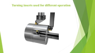
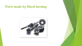
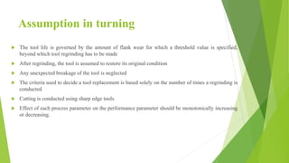
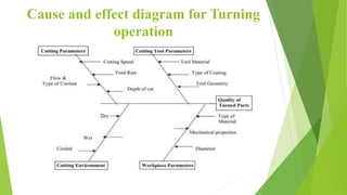
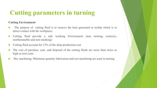
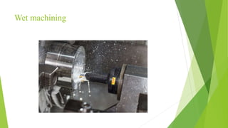
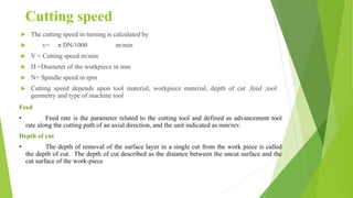
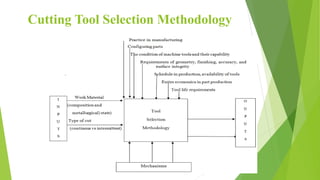
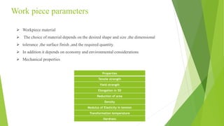
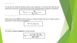
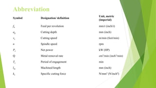
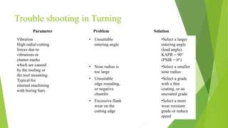
Machining Technology
Turning
Dr. K.Sivasakthivel
S. Manikandan
Department of Mechanical Engineering
Turning
 Turning is the form of machining process which uses a single-point cutting tool for material
removal.
 The process consists of a machine, workpiece, cutting tool and fixture. The workpiece is held
in the job holding device and attached to the turning center which rotates at high speeds.
 The required shape is obtained by feeding the cutting tool into the workpiece, also the
identification of necessary cutting parameter for achieving better cutting performance and
good quality depends on manufacturer handbook, the experience of the operator or trial and
error method.
Turning inserts used for different operation
Hard turning
 In manufacturing, hard turning has emerged as a potential option operation for finishing
products by eliminating grinding.
 Materials with more than 45 HRC machined by robust machining process, but actual hard
turning occurs in the hardness range of 58 HRC to 68 HRC.
 In hard turning the surface finish of 0.2 to 0.8 micrometer, the roundness of 1 to 5 micrometer
and diameter tolerance of + 3 to 7 micrometers can easily reach.
 Materials such as hardened alloy steel, tool steels, bearing steel, Inconel, case hardened steels,
nitride irons, hard chrome coated steels, metallurgical parts heat-treated by powder and
titanium alloys are used as a hard turning workpiece.
 The accuracy level of hard turning depends upon level of machine rigidity.
Benefits of hard turning
 By hard turning, complex parts made easily.
 The shape of the workpiece changes easily and rapidly.
 With one set-up, more operations can be carried out.
 The rate of material removal is more.
 CNC lathe used for hard turning.
 Metal chips generated during operations are environment-friendly.
 Coolant not required.
 Less tool inventory.
Limitations of Hard Turning
 Compared to grinding tooling cost is more in hard machining.
 The ratio of (L/D) Length to Diameter need to be less, i.e., 4:1.
 Tool temperature increased by reducing coolant usage.
 The wear of tool increased by reducing the coolant usage, hence tool life decreases.
 The thickness of the white layer generated during machining gets increases with increase in tool wear.
Hard turning applications
 Industries that deal with machining Titanium alloy for production of automotive parts, medical
devices, and computer spares.
 Aircraft and die mold industries involving machining of more extended Titanium alloy parts.
 Valves operate at higher spindle speed.
 Hard machining strategy stands useful in case of machining intricate cores, cavity mold machining and for
machining complex aircraft structural components.
 Materials machined at high cutting speed, high feed rate, and high removal rate.
Parts made by Hard turning
Assumption in turning
 The tool life is governed by the amount of flank wear for which a threshold value is specified,
beyond which tool regrinding has to be made
 After regrinding, the tool is assumed to restore its original condition
 Any unexpected breakage of the tool is neglected
 The criteria used to decide a tool replacement is based solely on the number of times a regrinding is
conducted
 Cutting is conducted using sharp edge tools
 Effect of each process parameter on the performance parameter should be monotonically increasing
or decreasing.
Cause and effect diagram for Turning
operation
Cutting parameters in turning
Cutting Environment
 The purpose of cutting fluid is to remove the heat generated at tooltip which is in
direct contact with the workpiece.
 Cutting fluid provide a safe working Environment (non misting, nontoxic,
nonflammable and non smoking)
 Cutting fluid account for 15% of the shop production cost
 The cost of purchase ,care ,and disposal of the cutting fluids are more than twice as
high as tool costs.
 Dry machining, Minimum quantity lubrication and wet machining are used in turning.
Wet machining
Cutting speed
 The cutting speed in turning is calculated by
 v= π DN/1000 m/min
 V = Cutting speed m/min
 D =Diameter of the workpiece in mm
 N= Spindle speed in rpm
 Cutting speed depends upon tool material, workpiece material, depth of cut ,feed ,tool
geometry and type of machine tool
Feed
• Feed rate is the parameter related to the cutting tool and defined as advancement tool
rate along the cutting path of an axial direction, and the unit indicated as mm/rev.
Depth of cut
• The depth of removal of the surface layer in a single cut from the work piece is called
the depth of cut. The depth of cut described as the distance between the uncut surface and the
cut surface of the work-piece
Cutting Tool Selection Methodology
Turning inserts different shape
Insert specification
CNMG 120404 SF 505 F indicates that
C Insert shape (Double-sided 800 rhombic insert)
N Clearance angle
M Tolerance on size
G Insert type
12 Cutting edge length
04 Thickness
04 Nose radius
SF 505 F indicates insert material
SELECTION OF Turning INSERTS
 ​The insert shape should be selected relative to the entering angle accessibility required of
the tool. The largest possible nose angle should be selected to provide insert strength and
reliability. However, this has to be balanced against the variation of cuts that need to be
performed.
 A large nose angle is strong, but requires more machine power and has a higher tendency for
vibration.
 A small nose angle is weaker and has a small cutting edge engagement, both of which can
make it more sensitive to the effects of heat.
 Selection of inserts is based on accuracy, quantity, workpiece material, availability of
machine tools and tool material.
 The knowledge of workpiece materials, geometries, and limitations of the cutting tool are
also essential.
 The cost of cutting tool cost is about 3 percent of the total component cost. Further
classification of tools can be done based on the cutting edge material, method of clamping
and geometry
Turning heat resistant super alloys (HRSA)
 A super alloy has excellent mechanical strength and resistance to creep (the tendency
for solids to slowly move or deform under stress) at high temperatures. It also offers
good corrosion/oxidation resistance. HRSA can be divided into four material groups:
 Nickel-based (for example Inconel)
 Iron-based
 Cobalt-based
 Titanium alloys (titanium can be pure or with alpha and beta structures)
 The machinability of both HRSA and titanium is poor, especially in aged conditions,
requiring particular demands on the cutting tools. It is important to use sharp edges to
prevent the formation of so-called white layers with different hardness and residual
stress.
 HRSA material: PVD and ceramic grades are commonly used when turning HRSA
materials. It is recommended to use geometries optimized for HRSA.
 Titanium alloys: Mainly use uncoated and PVD grades. It is recommended to use
geometries optimized for HRSA.
Characteristics of the TURNING insert
 High penetration hardness at elevated temperatures to resist abrasive wear.
 Resistance to deformation and prevents the edge from deforming during chip formation.
 High fracture toughness to resist edge chipping and breakage, especially interrupted cutting.
 Resist to diffusion, chemical reaction, and oxidation wear.
 The tool edge temperature reduced due to high thermal conductivity.
 High fatigue and shock resistance
 More stiffness to sustain accuracy.
 Provides lubricity to the work material for preventing built-up edge.
Work piece parameters
 Workpiece material
 The choice of material depends on the desired shape and size ,the dimensional
 tolerance ,the surface finish ,and the required quantity.
 In addition it depends on economy and environmental considerations
 Mechanical properties
Properties
Tensile strength
Yield strength
Elongation in 5D
Reduction of area
Density
Modulus of Elasticity in tension
Transformation temperature
Hardness
SELECTION OF MACHINE FOR
TURNING
 High static stiffness of machine elements such as spindles, joints, and structure
 Acceptable level of vibration
 Adequate damping capacity
 High feed rates and speeds
 The low rate of wear in sliding parts
 Low thermal distortion of machine elements.
 Part difficulty and complexity
CNC Turning Centre
Specification of CNC turning Centre
Model DX 200 5A
Swing over the bed (mm)
Standard turning diameter (mm)
Max. turning diameter (mm)
Max. turning length (mm)
500
250
365
500
X-Axis travel (Cross) (mm)
Z-Axis Travel (Longitudinal) (mm)
Rapid feed (x and z-axis) m/min
200
500
24
Power of spindle motor (kW) 7.5
The range of spindle speed (rpm) 50-4000
Positional accuracy (mm) 0.007
Repeatability (mm) 0.005
Machining time
It is the time for which the machine works on the component, i.e. from the time when the tool
touches the work piece to when the tool leaves the component after completion of operation.
Material removal rate
Metal removal rate (MRR) in metal cutting is a volume of chips removed in 1 minute, and it is
measured in a three-dimensional quantity.
Cutting power
The amount of power required to cut that material.
Symbol Designation/ definition
Unit, metric
(imperial)
fn Feed per revolution​ mm/r (inch/r)​
ap Cutting depth​ mm (inch)​
vc Cutting speed​ m/min (feet/min)​
n Spindle speed rpm​​
Pc Net power kW (HP)
Q Metal removal rate cm3/min (inch3/min)
Tc Period of engagement​ min​
lm Machined length​ mm (inch)
kc Specific cutting force N/mm2 (N/inch2)
Abbreviation
Trouble shooting in Turning
Vibration
High radial cutting
forces due to
vibrations or
chatter marks
which are caused
by the tooling or
the tool mounting.
Typical for
internal machining
with boring bars.
• Unsuitable
entering angle
•Select a larger
entering angle
(lead angle).
KAPR = 90°
(PSIR = 0°)
• Nose radius is
too large
•Select a smaller
nose radius
• Unsuitable
edge rounding,
or negative
chamfer
•Select a grade
with a thin
coating, or an
uncoated grade​
• Excessive flank
wear on the
cutting edge​
•Select a more
wear resistant
grade or reduce
speed
Parameter Problem Solution
Flank wear
Preferable wear type in every application. Offers
predictable and stable tool life.​​​
•Cutting
speed too
high
•Too
tough
grade
•Insufficie
nt wear
resistance
•Hard
inclusions
in
workpiece
material
•Reduce
cutting speed
•Select a
more
suitable
grade
depending
on toughness
demand or
wear
resistance​
References
 Abhang, LB & Hameedullah, M 2012, ‘Determination of optimum parameters for multi-
performance characteristics in turning by using grey relational analysis,’ The international journal
of advanced manufacturing technology, vol. 63, issue 1-4, pp. 13-24.
 Adarshkumar, K, Adarsh Kumar, K, Ch.Ratnam, Murthy, BSN, Satish Ben, B & Raghu Ram
Mohan Reddy, K 2012, ‘Optimization of Surface Roughness in Face Turning Operation in
Machining of En-8’, International Journal of Engineering Science & Advanced Technology, vol. 2,
issue 4, pp. 807–812
 Balamurugan Gopalsamy, Biswanatmondal & Sukamal Ghosh 2009, ‘Optimization of
machining parameters for hard machining: grey relational theory approach and ANOVA,’
International Journal of advanced manufacturing technology, vol. 45, pp. 1068-1086
 Chorng-Jyh Tzeng, Yu-Hsin Lin, Yung-Kuang Yang & Ming-Chang Jeng 2009, ‘Optimization
of turning operations with multiple performance characteristics using the Taguchi method and
Grey relational analysis,’ Journal of materials processing technology,
vol. 209, pp. 2753–2759.
 Durairaj, M & Gowri, S 2012, ‘Optimization of Inconel 600 Alloy Micro Turning Process Using
Grey Relational Analysis’, Advanced Materials Research, vol. 576, pp. 548-551.
 Manimaran, G & Pradeepkumar, M 2013, ‘Multi-response optimization of Grinding AISI
316 stainless steel using grey relational analysis’, Materials and Manufacturing Process, vol.
28, no. 4, pp. 418-423
 Narasimhulu, Andriya, Venkateswara Rao, P & Sudarson Ghosh 2012, ‘Dry machining of Ti-
6Al -4V using PVD Coated TiAlN’, proceeding of World Congress on Engineering, vol. 3
 Palanisamy Angappan, Selvaraj Thangiah & Sivasankaran Subbarayan 2017, ‘Taguchi-based
grey relational analysis for modeling and optimizing machining parameters through the dry
turning of Incoloy 800H’, Journal of Mechanical Science and Technology, vol. 31,
issue 9, pp. 4159–4165
 Radhakrishnan Ramanujam, Nambimuthukrishnan & Ramasamy Raju 2011, ‘Optimization of cutting
parameters for turning Al-Sic (10p) MMC using ANOVA and Grey relational analysis’, International
Journal of precision engineering and manufacturing, vol. 12, pp. 651-656.
 Raju Shri Hari Pawade & Suhas S Joshi 2011, ‘Multi-objective optimization of surface roughness and
cutting forces in the high-speed turning of Inconel 718 using Taguchi grey relational analysis (TGRA)’,
The international journal of advanced manufacturing technology, vol. 56, issue 1-4, pp. 47-62.
 Sivaiah, P & Chakradhar, D 2017, ‘Multi-objective optimization of cryogenic turning process using
Taguchi based grey relational analysis’, International Journal of Machining & Machinability of
Materials, International Journal of Machining and Machinability of Materials, vol. 19, pp. 297–312.
 Venkatesh Ganta, K, Srinivasa Sagar & Chakradhar, D 2017, ‘Multi-objective optimization of
thermally enhanced machining parameters of Inconel 718 using grey relational analysis’, Int. J.
Machining and Machinability of Materials, vol. 19, no. 1, pp. 57-75.
Thank you

Machining Technology-Turning

  • 1.
    Machining Technology Turning Dr. K.Sivasakthivel S.Manikandan Department of Mechanical Engineering
  • 2.
    Turning  Turning isthe form of machining process which uses a single-point cutting tool for material removal.  The process consists of a machine, workpiece, cutting tool and fixture. The workpiece is held in the job holding device and attached to the turning center which rotates at high speeds.  The required shape is obtained by feeding the cutting tool into the workpiece, also the identification of necessary cutting parameter for achieving better cutting performance and good quality depends on manufacturer handbook, the experience of the operator or trial and error method.
  • 3.
    Turning inserts usedfor different operation
  • 4.
    Hard turning  Inmanufacturing, hard turning has emerged as a potential option operation for finishing products by eliminating grinding.  Materials with more than 45 HRC machined by robust machining process, but actual hard turning occurs in the hardness range of 58 HRC to 68 HRC.  In hard turning the surface finish of 0.2 to 0.8 micrometer, the roundness of 1 to 5 micrometer and diameter tolerance of + 3 to 7 micrometers can easily reach.  Materials such as hardened alloy steel, tool steels, bearing steel, Inconel, case hardened steels, nitride irons, hard chrome coated steels, metallurgical parts heat-treated by powder and titanium alloys are used as a hard turning workpiece.  The accuracy level of hard turning depends upon level of machine rigidity.
  • 5.
    Benefits of hardturning  By hard turning, complex parts made easily.  The shape of the workpiece changes easily and rapidly.  With one set-up, more operations can be carried out.  The rate of material removal is more.  CNC lathe used for hard turning.  Metal chips generated during operations are environment-friendly.  Coolant not required.  Less tool inventory.
  • 6.
    Limitations of HardTurning  Compared to grinding tooling cost is more in hard machining.  The ratio of (L/D) Length to Diameter need to be less, i.e., 4:1.  Tool temperature increased by reducing coolant usage.  The wear of tool increased by reducing the coolant usage, hence tool life decreases.  The thickness of the white layer generated during machining gets increases with increase in tool wear.
  • 7.
    Hard turning applications Industries that deal with machining Titanium alloy for production of automotive parts, medical devices, and computer spares.  Aircraft and die mold industries involving machining of more extended Titanium alloy parts.  Valves operate at higher spindle speed.  Hard machining strategy stands useful in case of machining intricate cores, cavity mold machining and for machining complex aircraft structural components.  Materials machined at high cutting speed, high feed rate, and high removal rate.
  • 8.
    Parts made byHard turning
  • 9.
    Assumption in turning The tool life is governed by the amount of flank wear for which a threshold value is specified, beyond which tool regrinding has to be made  After regrinding, the tool is assumed to restore its original condition  Any unexpected breakage of the tool is neglected  The criteria used to decide a tool replacement is based solely on the number of times a regrinding is conducted  Cutting is conducted using sharp edge tools  Effect of each process parameter on the performance parameter should be monotonically increasing or decreasing.
  • 10.
    Cause and effectdiagram for Turning operation
  • 11.
    Cutting parameters inturning Cutting Environment  The purpose of cutting fluid is to remove the heat generated at tooltip which is in direct contact with the workpiece.  Cutting fluid provide a safe working Environment (non misting, nontoxic, nonflammable and non smoking)  Cutting fluid account for 15% of the shop production cost  The cost of purchase ,care ,and disposal of the cutting fluids are more than twice as high as tool costs.  Dry machining, Minimum quantity lubrication and wet machining are used in turning.
  • 12.
  • 13.
    Cutting speed  Thecutting speed in turning is calculated by  v= π DN/1000 m/min  V = Cutting speed m/min  D =Diameter of the workpiece in mm  N= Spindle speed in rpm  Cutting speed depends upon tool material, workpiece material, depth of cut ,feed ,tool geometry and type of machine tool Feed • Feed rate is the parameter related to the cutting tool and defined as advancement tool rate along the cutting path of an axial direction, and the unit indicated as mm/rev. Depth of cut • The depth of removal of the surface layer in a single cut from the work piece is called the depth of cut. The depth of cut described as the distance between the uncut surface and the cut surface of the work-piece
  • 14.
  • 15.
  • 16.
    Insert specification CNMG 120404SF 505 F indicates that C Insert shape (Double-sided 800 rhombic insert) N Clearance angle M Tolerance on size G Insert type 12 Cutting edge length 04 Thickness 04 Nose radius SF 505 F indicates insert material
  • 17.
    SELECTION OF TurningINSERTS  ​The insert shape should be selected relative to the entering angle accessibility required of the tool. The largest possible nose angle should be selected to provide insert strength and reliability. However, this has to be balanced against the variation of cuts that need to be performed.  A large nose angle is strong, but requires more machine power and has a higher tendency for vibration.  A small nose angle is weaker and has a small cutting edge engagement, both of which can make it more sensitive to the effects of heat.  Selection of inserts is based on accuracy, quantity, workpiece material, availability of machine tools and tool material.  The knowledge of workpiece materials, geometries, and limitations of the cutting tool are also essential.  The cost of cutting tool cost is about 3 percent of the total component cost. Further classification of tools can be done based on the cutting edge material, method of clamping and geometry
  • 18.
    Turning heat resistantsuper alloys (HRSA)  A super alloy has excellent mechanical strength and resistance to creep (the tendency for solids to slowly move or deform under stress) at high temperatures. It also offers good corrosion/oxidation resistance. HRSA can be divided into four material groups:  Nickel-based (for example Inconel)  Iron-based  Cobalt-based  Titanium alloys (titanium can be pure or with alpha and beta structures)  The machinability of both HRSA and titanium is poor, especially in aged conditions, requiring particular demands on the cutting tools. It is important to use sharp edges to prevent the formation of so-called white layers with different hardness and residual stress.  HRSA material: PVD and ceramic grades are commonly used when turning HRSA materials. It is recommended to use geometries optimized for HRSA.  Titanium alloys: Mainly use uncoated and PVD grades. It is recommended to use geometries optimized for HRSA.
  • 19.
    Characteristics of theTURNING insert  High penetration hardness at elevated temperatures to resist abrasive wear.  Resistance to deformation and prevents the edge from deforming during chip formation.  High fracture toughness to resist edge chipping and breakage, especially interrupted cutting.  Resist to diffusion, chemical reaction, and oxidation wear.  The tool edge temperature reduced due to high thermal conductivity.  High fatigue and shock resistance  More stiffness to sustain accuracy.  Provides lubricity to the work material for preventing built-up edge.
  • 20.
    Work piece parameters Workpiece material  The choice of material depends on the desired shape and size ,the dimensional  tolerance ,the surface finish ,and the required quantity.  In addition it depends on economy and environmental considerations  Mechanical properties Properties Tensile strength Yield strength Elongation in 5D Reduction of area Density Modulus of Elasticity in tension Transformation temperature Hardness
  • 21.
    SELECTION OF MACHINEFOR TURNING  High static stiffness of machine elements such as spindles, joints, and structure  Acceptable level of vibration  Adequate damping capacity  High feed rates and speeds  The low rate of wear in sliding parts  Low thermal distortion of machine elements.  Part difficulty and complexity
  • 22.
  • 23.
    Specification of CNCturning Centre Model DX 200 5A Swing over the bed (mm) Standard turning diameter (mm) Max. turning diameter (mm) Max. turning length (mm) 500 250 365 500 X-Axis travel (Cross) (mm) Z-Axis Travel (Longitudinal) (mm) Rapid feed (x and z-axis) m/min 200 500 24 Power of spindle motor (kW) 7.5 The range of spindle speed (rpm) 50-4000 Positional accuracy (mm) 0.007 Repeatability (mm) 0.005
  • 24.
    Machining time It isthe time for which the machine works on the component, i.e. from the time when the tool touches the work piece to when the tool leaves the component after completion of operation. Material removal rate Metal removal rate (MRR) in metal cutting is a volume of chips removed in 1 minute, and it is measured in a three-dimensional quantity. Cutting power The amount of power required to cut that material.
  • 25.
    Symbol Designation/ definition Unit,metric (imperial) fn Feed per revolution​ mm/r (inch/r)​ ap Cutting depth​ mm (inch)​ vc Cutting speed​ m/min (feet/min)​ n Spindle speed rpm​​ Pc Net power kW (HP) Q Metal removal rate cm3/min (inch3/min) Tc Period of engagement​ min​ lm Machined length​ mm (inch) kc Specific cutting force N/mm2 (N/inch2) Abbreviation
  • 26.
    Trouble shooting inTurning Vibration High radial cutting forces due to vibrations or chatter marks which are caused by the tooling or the tool mounting. Typical for internal machining with boring bars. • Unsuitable entering angle •Select a larger entering angle (lead angle). KAPR = 90° (PSIR = 0°) • Nose radius is too large •Select a smaller nose radius • Unsuitable edge rounding, or negative chamfer •Select a grade with a thin coating, or an uncoated grade​ • Excessive flank wear on the cutting edge​ •Select a more wear resistant grade or reduce speed Parameter Problem Solution
  • 27.
    Flank wear Preferable weartype in every application. Offers predictable and stable tool life.​​​ •Cutting speed too high •Too tough grade •Insufficie nt wear resistance •Hard inclusions in workpiece material •Reduce cutting speed •Select a more suitable grade depending on toughness demand or wear resistance​
  • 28.
    References  Abhang, LB& Hameedullah, M 2012, ‘Determination of optimum parameters for multi- performance characteristics in turning by using grey relational analysis,’ The international journal of advanced manufacturing technology, vol. 63, issue 1-4, pp. 13-24.  Adarshkumar, K, Adarsh Kumar, K, Ch.Ratnam, Murthy, BSN, Satish Ben, B & Raghu Ram Mohan Reddy, K 2012, ‘Optimization of Surface Roughness in Face Turning Operation in Machining of En-8’, International Journal of Engineering Science & Advanced Technology, vol. 2, issue 4, pp. 807–812  Balamurugan Gopalsamy, Biswanatmondal & Sukamal Ghosh 2009, ‘Optimization of machining parameters for hard machining: grey relational theory approach and ANOVA,’ International Journal of advanced manufacturing technology, vol. 45, pp. 1068-1086  Chorng-Jyh Tzeng, Yu-Hsin Lin, Yung-Kuang Yang & Ming-Chang Jeng 2009, ‘Optimization of turning operations with multiple performance characteristics using the Taguchi method and Grey relational analysis,’ Journal of materials processing technology, vol. 209, pp. 2753–2759.  Durairaj, M & Gowri, S 2012, ‘Optimization of Inconel 600 Alloy Micro Turning Process Using Grey Relational Analysis’, Advanced Materials Research, vol. 576, pp. 548-551.
  • 29.
     Manimaran, G& Pradeepkumar, M 2013, ‘Multi-response optimization of Grinding AISI 316 stainless steel using grey relational analysis’, Materials and Manufacturing Process, vol. 28, no. 4, pp. 418-423  Narasimhulu, Andriya, Venkateswara Rao, P & Sudarson Ghosh 2012, ‘Dry machining of Ti- 6Al -4V using PVD Coated TiAlN’, proceeding of World Congress on Engineering, vol. 3  Palanisamy Angappan, Selvaraj Thangiah & Sivasankaran Subbarayan 2017, ‘Taguchi-based grey relational analysis for modeling and optimizing machining parameters through the dry turning of Incoloy 800H’, Journal of Mechanical Science and Technology, vol. 31, issue 9, pp. 4159–4165  Radhakrishnan Ramanujam, Nambimuthukrishnan & Ramasamy Raju 2011, ‘Optimization of cutting parameters for turning Al-Sic (10p) MMC using ANOVA and Grey relational analysis’, International Journal of precision engineering and manufacturing, vol. 12, pp. 651-656.  Raju Shri Hari Pawade & Suhas S Joshi 2011, ‘Multi-objective optimization of surface roughness and cutting forces in the high-speed turning of Inconel 718 using Taguchi grey relational analysis (TGRA)’, The international journal of advanced manufacturing technology, vol. 56, issue 1-4, pp. 47-62.  Sivaiah, P & Chakradhar, D 2017, ‘Multi-objective optimization of cryogenic turning process using Taguchi based grey relational analysis’, International Journal of Machining & Machinability of Materials, International Journal of Machining and Machinability of Materials, vol. 19, pp. 297–312.  Venkatesh Ganta, K, Srinivasa Sagar & Chakradhar, D 2017, ‘Multi-objective optimization of thermally enhanced machining parameters of Inconel 718 using grey relational analysis’, Int. J. Machining and Machinability of Materials, vol. 19, no. 1, pp. 57-75.
  • 30.