Downloaded 261 times
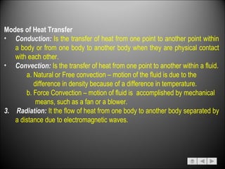
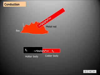
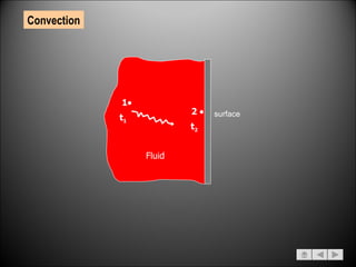
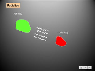
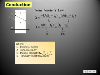
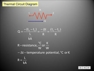
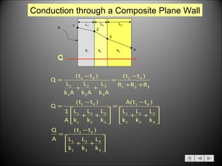
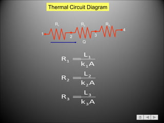
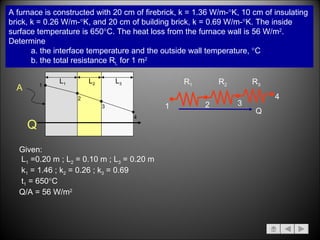
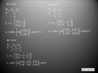
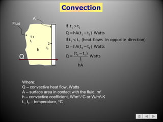
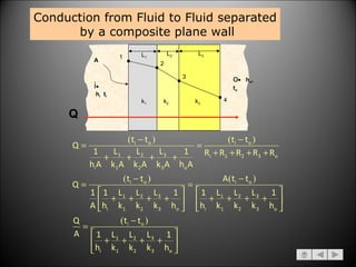
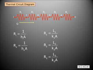
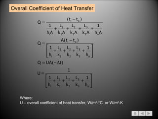
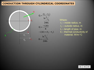
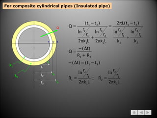
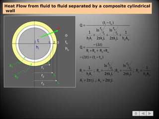
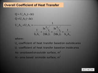
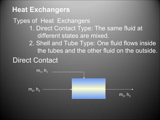
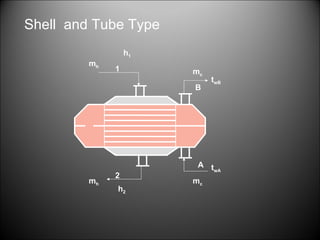
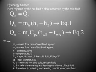
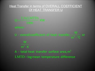
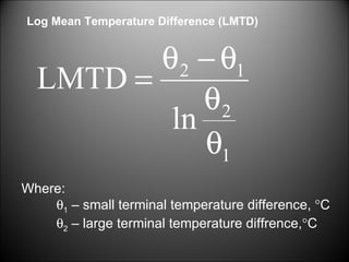

The document discusses different modes of heat transfer including conduction, convection, and radiation. It provides examples of heat transfer through a metal rod, fluid movement, and electromagnetic waves. Formulas are given for calculating heat transfer by conduction through plane walls, cylindrical pipes, and composite materials using thermal conductivity and temperature differences. Methods for determining overall heat transfer coefficients and heat exchangers are also summarized.


