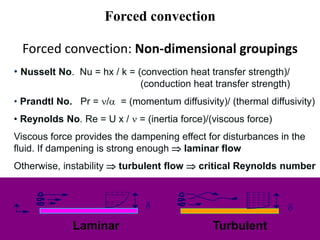
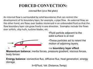
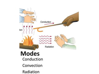
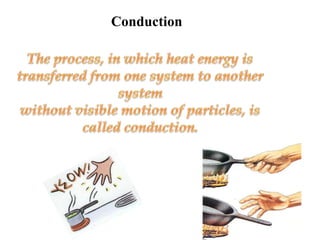
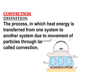
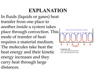
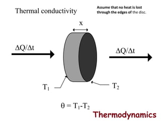
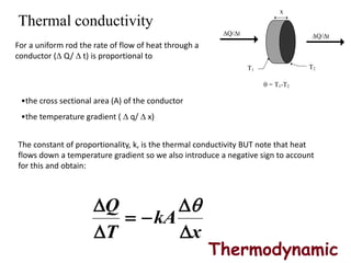
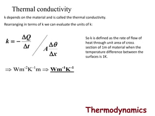
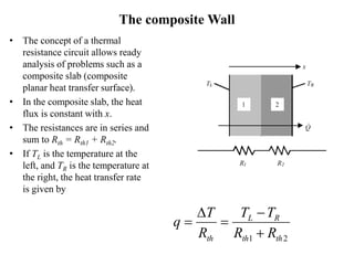
This document provides information on different modes of heat transfer including conduction, convection and radiation. It defines conduction as the transfer of heat through direct contact of particles over large distances. Convection is defined as the transfer of heat from one place to another inside a system through fluid motion, requiring a material medium. Radiation is defined as the transfer of heat in the form of electromagnetic waves with no need for a material medium. The document also discusses various concepts related to these modes of heat transfer such as Fourier's law of conduction, heat transfer coefficients, Nusselt number, Prandtl number and Reynolds number.


![T(y)q”
y
U T
Ts
u(y)
U
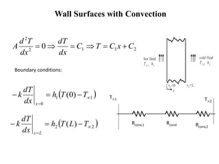
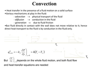
Convection rate equation
Main purpose of convective heat
transfer analysis is to determine:
• flow field
• temperature field in fluid
• heat transfer coefficient, h
q’’=heat flux = h(Ts - T)
q’’ = -k(T/ y)y=0
Hence, h = [-k(T/ y)y=0] / (Ts - T)
The expression shows that in order to determine h, we
must first determine the temperature distribution in the
thin fluid layer that coats the wall.](https://image.slidesharecdn.com/heattransfer-190418113345/85/Heat-transfer-28-320.jpg)