Downloaded 32 times
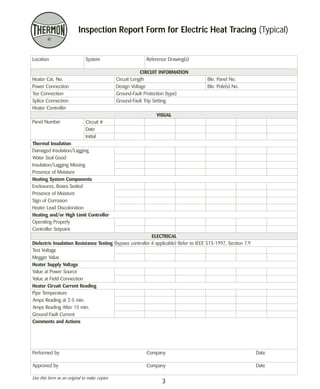
![Symptom Possible Cause Remedy
Notes . . .
1. Flexible, plastic-jacketed heating cables may be field-spliced; MI cables usually require replacement.
2. Mechanical thermostat sensors cannot be repaired or replaced; RTD or thermocouple sensors can be replaced. Some controllers have replaceable
contacts/relays or may require a manual reset if a “trip-off” condition on the heating circuit was detected.
3. The operation of most electric heat tracing cables is dramatically affected by changes in the supply voltage. Before making any changes, consult the
cable manufacturer with information on the alternate voltages available. Otherwise, cable failure and/or an electrical safety hazard may result in
some situations.
5
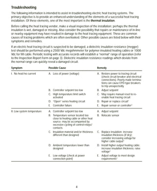
III. Low temperature in
sections
A. Wet, damaged or missing insulation
B. Parallel heating cable; open element
or damaged matrix
C. Heat sinks (valves, pumps, pipe
supports, etc.)
D. Significant changes in elevation
along length of the heat-traced pipe
A. Repair or replace insulation and
jacket
B. Repair or replace; splice kits are
available from cable manufacturer
C. Insulate heat sinks or increase
amount of tracing on heat sinks
D. Consider dividing heating circuit
into separate, independently
controlled segments
IV. High system temperature A. Controller “on” continuously
B. Controller failed with contacts
closed
C. Sensor located on uninsulated pipe
or too close to heat sink
D. Backup heating circuit controller
“on” continuously
A. Adjust setpoint or replace sensor2
B. Replace sensor or controller2
C. Relocate sensor to an area repre-sentative
of conditions along entire
pipe length
D. Adjust setpoint or replace backup
controller
V. Excessive cycling A. Temperature sensor located too
close to heating cable or other heat
source; may be accompanied by
low system temperature
B. Ambient temperature near con-troller
setpoint
C. Connected voltage too high
D. Heating cable output too high
(overdesign)
E. Controller differential too narrow
A. Relocate sensor
B. Temporarily alter controller setpoint
C. Lower voltage
D. Install lower output heating cable or
lower voltage
E. Widen differential or replace con-troller
to avoid premature contact
failure
VI. Temperature variations
from setpoint along
pipeline
A. Unanticipated flow patterns or
process operating temperatures
B. Inconsistent cable installation along
pipeline
C. Inconsistent cable performance
A. Redistribute heating circuits to ac-commodate
existing flow patterns;
confirm process conditions
B. Check method of cable installation,
especially at heat sinks
C. Compare calculated watts/foot
[(volts x amps) ÷ length] for the
measured pipe temperature with
designed cable output for the same
temperature; regional damage to
parallel cable can cause partial
failure](https://image.slidesharecdn.com/heattracingmaintenanceandtroubleshooting-141014164056-conversion-gate01/85/Electric-Heat-tracing-maintenance-and-troubleshooting-by-Thermon-6-320.jpg)


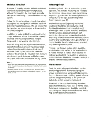
This document provides an overview of electric heat tracing systems and components, installation and testing procedures, maintenance guidelines, and troubleshooting tips. A typical system includes electric heating cable, power connections, controls, splices and terminations. It should be tested after installation but before insulation using a megohmmeter. Ongoing maintenance includes periodic inspections and testing to monitor performance over time. Proper thermal insulation is critical for heat retention and system effectiveness. Common issues like damaged insulation, low temperatures, and excessive cycling are addressed along with potential causes and remedies.


