Downloaded 187 times


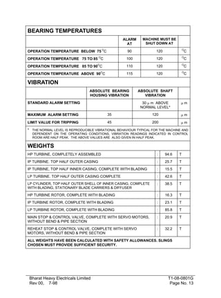


The document provides technical specifications for erecting a 500 MW steam turbine from KWU design, including: - It is a three cylinder reheat condensing turbine with a single flow HP turbine, double flow IP turbine, and double flow LP turbine. - It has main stop and control valves, reheat stop and control valves, and extraction swing check valves. - The rated speed is 50.0 revolutions per second and the maximum under valve wide open condition is 524.2 MW.