Thermography test of electrical panels
•
0 likes•1,777 views

Thermography test of electrical panels Thermography test of electrical panelThermography test of electrical panelThermography test of electrical panelThermography test of electrical panelThermography test of electrical panelThermography test of electrical panelThermography test of electrical panelThermography test of electrical panelThermography test of electrical panelThermography test of electrical panelThermography test of electrical panelThermography test of electrical panelThermography test of electrical panelThermography test of electrical panelThermography test of electrical panelThermography test of electrical panel

Recommended
More Related Content
What's hot
What's hot (20)
Similar to Thermography test of electrical panels
Similar to Thermography test of electrical panels (20)
More from Power System Operation
More from Power System Operation (20)
Recently uploaded
Recently uploaded (20)
Thermography test of electrical panels
- 1. THERMOGRAPHY TEST OF ELECTRICAL PANELS
- 2. Infrared thermography is a test that can be utilised to identify unbalanced loads, poor connections, deteriorated insulation or any other issues in energized electrical panels or components without dismantling the components. These problems may lead to excess power use, increased maintenance costs, or catastrophic equipment failure resulting in unscheduled service interruptions, equipment damage, or other problems.
- 3. Why is Thermography Testing of Electrical Panel Important? Performing an infrared testing will highlight problems with electrical infrastructure under load during the testing process as these areas will manifest as anomalous temperatures shown in the live image on the thermal imaging camera. Moreover, failures can result in employees to be bared to live electrical circuits, making them prone to severe injury or death from electrocution. By detecting high-resistance connections and repairing them, the likelihood of a breakdown of the electrical wires and related components will be reduced.
- 4. Other benefits of finding and fixing these faults are the cost effectiveness that comes from energy conservation and reduction in shutdown and repair charge. High resistance in circuits causes an increase in current flow. When current flow is increased, the resulting power consumption will increase. Additionally, large current draw can lead to severe electrical circuit components, like circuit breakers, fuses and transformers, to collapse prematurely. These failures result in higher maintenance and repair costs, and resultant business interruptions.
- 5. Benefits of Doing Thermography Testing of Electrical Panel •Determines if the components and system have been properly installed and are not damaged •Reduces downtime •Reduces risk of equipment failure •Increases safety •Improves insurability •Reduces liability exposure of the designers and installers •Improves system performance •Determines whether components and systems operate properly and meet the design intent •Determines if components and systems are in compliance with the project specifications and design •Reduces construction schedule delays •Saves money
- 6. What is Performed During Infrared Thermography Testing of Electrical Panels? Electrical switchgear and panels are the bloodline to supply electricity throughout commercial, manufacturing and industrial buildings. Without it, production stops and money are lost. Infrared is a proven tool to identify electrical problems prior to failure, allowing our clients to take proactive steps to prevent costly and sometimes dangerous electrical outages. Infrared thermography testing is a way of examining electrical components by attaining heat distribution images. This testing method is based on the fact that most components in a system show an increase in temperature when malfunctioning. The increase in temperature in an electrical circuit could be due to lose connections or a worn bearing in the case of mechanical equipment. By observing the heat patterns in operational system components, faults can be located and their seriousness evaluated.
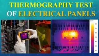
- 7. How is Thermography Testing of Electrical Panels Done? The testing device utilised by inspector is an infrared camera or a thermal imager. These devices measure the natural emissions of infrared radiation from a heated object and produce a thermal picture. Modern Thermal Imagers are portable with easily operated controls. As direct contact with the system isn’t needed, testing can be done under completely energized state leading to no loss of production or downtime.
- 8. Thermal testing can identify following factors: •High resistance connections •Hot spots •Over loaded cables •Over loaded fuses or breakers •Imminent motor or conveyor bearing failure •Motor windings over heating •Overheating in distribution equipment •Phase load imbalance •Hot spots in high level lighting (easily scanned from the floor) •Heat build-up in overcrowded trunking •Thermal insulation breakdown (hot or cold) •Thermal loss •Damp ingress
- 9. Following are the Procedure for Thermography Testing of Electrical Panels •Panel to be tested shall be energized and under adequate load; ideally this is normal operating load. •Subject panel shall be externally examined before opening or removing any protective covers to determine the possible presence of unsafe conditions. If unusual heating or dangerous conditions exists, a qualified assistant must take suitable corrective steps before starting the infrared testing. •Electrical panel enclosures shall be opened to provide line-of-sight access to components contained therein. In some cases, further disassembly may be required to allow for a complete infrared testing. •Steps should be taken to make sure that the subject panel can be sufficiently and fully imaged. •Infrared testing may be qualitative or quantitative in nature. •While carrying out qualitative testing, the thermographer must use a thermal imager, unlike an imaging radiometer used in case of quantitative testing, with resolution adequate to offer clear image of the tested panels. •When carrying out IR testing, the thermographer must take maximum effort to make sure the precision of non-contact temperature readings. •If possible, alike components under alike load must be compared to each other.
- 10. •Components showing abnormal operating temperatures or thermal patterns must be considered as exclusions and reported with a thermal image or thermogram and visible light image. •Thermal figures must be saved on appropriately. Maximum effort must be taken to make sure the thermal picture is in focus. •Visible light pictures images must be captured with a daylight camera essential to the infrared imager. •Visible light pictures must be correctly visible to make sure appropriate detail can be obtained. •Particular attention should be given to perspective, focus, contrast, resolution, and lighting. •Both thermal and visible images must be incorporated in the report. Documentation or Report Preparation *The distance from the infrared imager to the exception. *Whenever possible, the maximum rated load of the exception and its measured load at the time of the testing. *The reflected temperature, emittance and transmittance values needed to find the temperature of the faulty component. *When considering absolute temperature, the surface temperature of the exception and the standard temperature referenced are taken into account. *If desired, an evaluation of the temperature severity of the exception. *If needed, a repair priority rating for the faulty component depending on its temperature severity rating