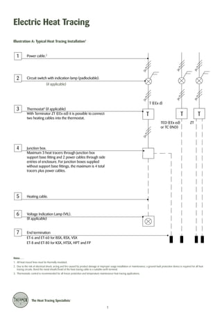
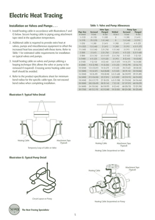
This document provides installation procedures and guidelines for electric heat tracing systems. It includes:
- Illustrations of typical heat tracing installations on pipes, elbows, supports and flanges
- Requirements for receiving, storing and handling heat tracing cables properly
- Guidelines for initial installation including cable allowances and minimum bend radii
- Procedures for completing the installation including securing cables, insulation resistance testing, and making power connections
- Tables listing recommended cable allowances for valves, pumps and other equipment to ensure adequate heat distribution
DevOps and Testing slides at DASA ConnectKari Kakkonen
My and Rik Marselis slides at 30.5.2024 DASA Connect conference. We discuss about what is testing, then what is agile testing and finally what is Testing in DevOps. Finally we had lovely workshop with the participants trying to find out different ways to think about quality and testing in different parts of the DevOps infinity loop.
In the rapidly evolving landscape of technologies, XML continues to play a vital role in structuring, storing, and transporting data across diverse systems. The recent advancements in artificial intelligence (AI) present new methodologies for enhancing XML development workflows, introducing efficiency, automation, and intelligent capabilities. This presentation will outline the scope and perspective of utilizing AI in XML development. The potential benefits and the possible pitfalls will be highlighted, providing a balanced view of the subject.
We will explore the capabilities of AI in understanding XML markup languages and autonomously creating structured XML content. Additionally, we will examine the capacity of AI to enrich plain text with appropriate XML markup. Practical examples and methodological guidelines will be provided to elucidate how AI can be effectively prompted to interpret and generate accurate XML markup.
Further emphasis will be placed on the role of AI in developing XSLT, or schemas such as XSD and Schematron. We will address the techniques and strategies adopted to create prompts for generating code, explaining code, or refactoring the code, and the results achieved.
The discussion will extend to how AI can be used to transform XML content. In particular, the focus will be on the use of AI XPath extension functions in XSLT, Schematron, Schematron Quick Fixes, or for XML content refactoring.
The presentation aims to deliver a comprehensive overview of AI usage in XML development, providing attendees with the necessary knowledge to make informed decisions. Whether you’re at the early stages of adopting AI or considering integrating it in advanced XML development, this presentation will cover all levels of expertise.
By highlighting the potential advantages and challenges of integrating AI with XML development tools and languages, the presentation seeks to inspire thoughtful conversation around the future of XML development. We’ll not only delve into the technical aspects of AI-powered XML development but also discuss practical implications and possible future directions.
Building RAG with self-deployed Milvus vector database and Snowpark Container...Zilliz
This talk will give hands-on advice on building RAG applications with an open-source Milvus database deployed as a docker container. We will also introduce the integration of Milvus with Snowpark Container Services.
Unlock the Future of Search with MongoDB Atlas_ Vector Search Unleashed.pdfMalak Abu Hammad
Discover how MongoDB Atlas and vector search technology can revolutionize your application's search capabilities. This comprehensive presentation covers:
* What is Vector Search?
* Importance and benefits of vector search
* Practical use cases across various industries
* Step-by-step implementation guide
* Live demos with code snippets
* Enhancing LLM capabilities with vector search
* Best practices and optimization strategies
Perfect for developers, AI enthusiasts, and tech leaders. Learn how to leverage MongoDB Atlas to deliver highly relevant, context-aware search results, transforming your data retrieval process. Stay ahead in tech innovation and maximize the potential of your applications.
#MongoDB #VectorSearch #AI #SemanticSearch #TechInnovation #DataScience #LLM #MachineLearning #SearchTechnology
Unlocking Productivity: Leveraging the Potential of Copilot in Microsoft 365, a presentation by Christoforos Vlachos, Senior Solutions Manager – Modern Workplace, Uni Systems
UiPath Test Automation using UiPath Test Suite series, part 5DianaGray10
Welcome to UiPath Test Automation using UiPath Test Suite series part 5. In this session, we will cover CI/CD with devops.
Topics covered:
CI/CD with in UiPath
End-to-end overview of CI/CD pipeline with Azure devops
Speaker:
Lyndsey Byblow, Test Suite Sales Engineer @ UiPath, Inc.
Dr. Sean Tan, Head of Data Science, Changi Airport Group
Discover how Changi Airport Group (CAG) leverages graph technologies and generative AI to revolutionize their search capabilities. This session delves into the unique search needs of CAG’s diverse passengers and customers, showcasing how graph data structures enhance the accuracy and relevance of AI-generated search results, mitigating the risk of “hallucinations” and improving the overall customer journey.
Securing your Kubernetes cluster_ a step-by-step guide to success !KatiaHIMEUR1
Today, after several years of existence, an extremely active community and an ultra-dynamic ecosystem, Kubernetes has established itself as the de facto standard in container orchestration. Thanks to a wide range of managed services, it has never been so easy to set up a ready-to-use Kubernetes cluster.
However, this ease of use means that the subject of security in Kubernetes is often left for later, or even neglected. This exposes companies to significant risks.
In this talk, I'll show you step-by-step how to secure your Kubernetes cluster for greater peace of mind and reliability.
zkStudyClub - Reef: Fast Succinct Non-Interactive Zero-Knowledge Regex ProofsAlex Pruden
This paper presents Reef, a system for generating publicly verifiable succinct non-interactive zero-knowledge proofs that a committed document matches or does not match a regular expression. We describe applications such as proving the strength of passwords, the provenance of email despite redactions, the validity of oblivious DNS queries, and the existence of mutations in DNA. Reef supports the Perl Compatible Regular Expression syntax, including wildcards, alternation, ranges, capture groups, Kleene star, negations, and lookarounds. Reef introduces a new type of automata, Skipping Alternating Finite Automata (SAFA), that skips irrelevant parts of a document when producing proofs without undermining soundness, and instantiates SAFA with a lookup argument. Our experimental evaluation confirms that Reef can generate proofs for documents with 32M characters; the proofs are small and cheap to verify (under a second).
Paper: https://eprint.iacr.org/2023/1886
How to Get CNIC Information System with Paksim Ga.pptxdanishmna97
Pakdata Cf is a groundbreaking system designed to streamline and facilitate access to CNIC information. This innovative platform leverages advanced technology to provide users with efficient and secure access to their CNIC details.
Maruthi Prithivirajan, Head of ASEAN & IN Solution Architecture, Neo4j
Get an inside look at the latest Neo4j innovations that enable relationship-driven intelligence at scale. Learn more about the newest cloud integrations and product enhancements that make Neo4j an essential choice for developers building apps with interconnected data and generative AI.
GraphSummit Singapore | The Art of the Possible with Graph - Q2 2024Neo4j
Neha Bajwa, Vice President of Product Marketing, Neo4j
Join us as we explore breakthrough innovations enabled by interconnected data and AI. Discover firsthand how organizations use relationships in data to uncover contextual insights and solve our most pressing challenges – from optimizing supply chains, detecting fraud, and improving customer experiences to accelerating drug discoveries.
Observability Concepts EVERY Developer Should Know -- DeveloperWeek Europe.pdfPaige Cruz
Monitoring and observability aren’t traditionally found in software curriculums and many of us cobble this knowledge together from whatever vendor or ecosystem we were first introduced to and whatever is a part of your current company’s observability stack.
While the dev and ops silo continues to crumble….many organizations still relegate monitoring & observability as the purview of ops, infra and SRE teams. This is a mistake - achieving a highly observable system requires collaboration up and down the stack.
I, a former op, would like to extend an invitation to all application developers to join the observability party will share these foundational concepts to build on:
UiPath Test Automation using UiPath Test Suite series, part 6DianaGray10
Welcome to UiPath Test Automation using UiPath Test Suite series part 6. In this session, we will cover Test Automation with generative AI and Open AI.
UiPath Test Automation with generative AI and Open AI webinar offers an in-depth exploration of leveraging cutting-edge technologies for test automation within the UiPath platform. Attendees will delve into the integration of generative AI, a test automation solution, with Open AI advanced natural language processing capabilities.
Throughout the session, participants will discover how this synergy empowers testers to automate repetitive tasks, enhance testing accuracy, and expedite the software testing life cycle. Topics covered include the seamless integration process, practical use cases, and the benefits of harnessing AI-driven automation for UiPath testing initiatives. By attending this webinar, testers, and automation professionals can gain valuable insights into harnessing the power of AI to optimize their test automation workflows within the UiPath ecosystem, ultimately driving efficiency and quality in software development processes.
What will you get from this session?
1. Insights into integrating generative AI.
2. Understanding how this integration enhances test automation within the UiPath platform
3. Practical demonstrations
4. Exploration of real-world use cases illustrating the benefits of AI-driven test automation for UiPath
Topics covered:
What is generative AI
Test Automation with generative AI and Open AI.
UiPath integration with generative AI
Speaker:
Deepak Rai, Automation Practice Lead, Boundaryless Group and UiPath MVP
Sudheer Mechineni, Head of Application Frameworks, Standard Chartered Bank
Discover how Standard Chartered Bank harnessed the power of Neo4j to transform complex data access challenges into a dynamic, scalable graph database solution. This keynote will cover their journey from initial adoption to deploying a fully automated, enterprise-grade causal cluster, highlighting key strategies for modelling organisational changes and ensuring robust disaster recovery. Learn how these innovations have not only enhanced Standard Chartered Bank’s data infrastructure but also positioned them as pioneers in the banking sector’s adoption of graph technology.
In his public lecture, Christian Timmerer provides insights into the fascinating history of video streaming, starting from its humble beginnings before YouTube to the groundbreaking technologies that now dominate platforms like Netflix and ORF ON. Timmerer also presents provocative contributions of his own that have significantly influenced the industry. He concludes by looking at future challenges and invites the audience to join in a discussion.
2. Electric Heat Tracing
Illustration A: Typical Heat Tracing Installation1
1
Power cable.2
2
Circuit switch with indication lamp (padlockable).
(if applicable)
T (EEx d)
3
Thermostat (if applicable)
With Terminator ZT (EEx ed) it is possible to connect
two heating cables into the thermostat.
3
T
T
TED (EEx ed)
or TC (IND)
4
Heating cable.
6
Voltage Indication Lamp (VIL).
(If applicable)
7
ZT
Junction box.
Maximum 3 heat tracers through junction box
support base fitting and 2 power cables through side
entries of enclosure. For junction boxes supplied
without support base fittings, the maximum is 4 total
tracers plus power cables.
5
T
End termination
ET-6 and ET-60 for BSX, RSX, VSX
ET-8 and ET-80 for KSX, HTSX, HPT and FP
Notes . . .
1. All heat-traced lines must be thermally insulated.
2. Due to the risk of electrical shock, arcing and fire caused by product damage or improper usage installation or maintenance, a ground-fault protection device is required for all heat
tracing circuits. Bond the metal sheath/braid of the heat tracing cable to a suitable earth terminal.
3. Thermostatic control is recommended for all freeze protection and temperature maintenance heat tracing applications.
1
3. INSTALLATION PROCEDURES
Complete Electric Heat Tracing System . . .
Types of Heating Cables1 . . .
1. Self-Regulating Heating Cables:
BSX™ (refer to Form TEP0067U)
1725 II 2 G & D Ex e II T5 or T6 DEMKO 02ATEX0132424, IECEx UL 06.0013 Ex e II T5 or T6
RSX™ 15 (refer to Form TEP0048U)2
1725
II 2 G Ex e II T4 to T6 KEMA 07ATEX0179, IECEx KEM 07.0052 Ex e II T4 to T6
HTSX™ (refer to Form TEP0074U)
1725
II 2 G & D Ex e II T2 or T3 DEMKO 02ATEX0120790, IECEx UL 06.0004 Ex e II T2 or T3
KSX™ (refer to Form TEP0072U)
1725
II 2 G Ex e II T3 to T6, II 2 D Ex tD A21 IP66/IP67 T200°C to T85°C FM 07ATEX0027, IECEx FMG 06.0009 Ex e II T3 to T6,
Ex tD A21 IP66/IP67 T200°C to T85°C
VSX™ (refer to Form TEP0008U)
1725 II 2 G & D Ex e II T3 DEMKO 02ATEX0152667, IECEx UL 05.0008 Ex e II T3
2. Power-Limiting Heating Cable:
HPT™ (refer to Form TEP0011U)
1725
II 2 G Ex e II T2 to T6, II 2 D Ex tD A21 T300°C to T85°C FM 07ATEX0028, IECEx FMG 06.0006 Ex e II T2 to T6
3. Parallel Constant Watt Heating Cable:
FP
(refer to Form TEP0016U)3
1725
II 2 G Ex e II T3 to T6, II 2 D Ex tD A21 IP66/IP67 T200°C to T85°C FM 07ATEX0016, IECEx FMG 06.0008 Ex e II T3 to T6,
Ex tD A21 IP66/IP67 T200°C to T85°C
4. Series Constant Watt Heating Cables:
TES™ (refer to Form TEP0063U)
1725
II 2 G EEx edm IIC T2 To T6 LCIE 00ATEX6014X
TESH™ (refer to Form TEP0070U)
1725
II 2 G EEx edm IIC T2 To T6 LCIE 00ATEX6014X
Notes . . .
1. Refer to the heating cable product specification sheets for temperature ratings as limited by the manufacturer.
2. For foundation heating with RSX, refer to Form TEP0059.
3. For foundation heating with FP, refer to Form TEP0079.
Site Practice . . .
1. Provide protective clothing, and other protective equipment needed to isolate employees from potential arc flash and shock
hazards identified in the analysis.
2. Provide training to employees for understanding the purpose/function of the electrical heat tracing and the electrical power
supply/control equipment, and how to recognize and avoid the hazards associated with operation and maintenance.
3. Apply safe work practices including the following:
• Identify the circuit or equipment to be de-energized and all possible sources of electrical energy supplies to the specfic
circuit or equipment.
• Disconnect both legs of the power supply cable at the circuit breakers, disconnect switches, and any other applicable
points.
• Apply lockout/tagout devices according to established procedures.
• Visually verify that the circuit disconnect devices are open prior to connecting power cable to heat tracers.
• Test for absence of voltage with an approved voltmeter (where the voltmeter is tested on a known circuit voltage
prior to and immediately following application).
• For protection against accidental energizing of supply conductors, apply temporary jumpers rated for the available fault
duty between each supply conductor and ground.
2
4. Electric Heat Tracing
Before Installing Cable . . .
Read and carefully follow all installation procedures when
installing a Thermon electric heat tracing system1. Product
certifications and performance of heat tracing system is
dependant upon proper installation with certified Thermon
components.
1. Before removing the heating cable from the reel, an insulation resistance test should be conducted. The cable
should be tested with a test voltage of at least 500 Vdc.
However, for polymer insulated heating cables, 2500 Vdc
is recommended. The minimum acceptable level should
not be less than 20 megohms. All test results should be
documented.
The system must be installed in accordance with the
regulations EN IEC 60079-14 and IEC 62086-2 for hazardous
areas (where applicable). The system installation must also
comply with all local and national electrical codes.
Testing should occur at the following stages of installation.
• While the cable is still on the reel
• After installing heating cable
• After installation of thermal insulation
• Prior to connecting cable to power
• As part of a routine maintenance program
Applications . . .
1. Electric heat tracing cables are used for freeze protection2
and/or temperature maintenance of piping, tanks and
instrumentation.
2. Heat tracing cables may be installed in ordinary (nonclassified) and hazardous (classified) locations depending on
the specific cable options and approvals. See ‘Types of
Heating Cables’ on page 2.
2. Be sure all piping and equipment to be traced is completely
installed, pressure tested and painted (if applicable)
3. Surface areas where heat tracing is to be installed must be
reasonably clean. Remove dirt, rust and scale with a wire
brush and oil and grease films with a suitable solvent.
Receiving, Storing and Handling . . .
Initial Installation . . .
1. Identify the heating cable to ensure the proper type and
quantity have been received. The cable model number
will be visible on parallel heating cables (on braided
cables, the information is printed on the jacket below the
braid); factory-fabricated series circuits will have an imprinted l.D. tag with pertinent data. Compare information
on heating cable with packing slip and purchase order to
verify receipt of correct shipment. For date of production,
contact Thermon.
1. Begin temporary installation at the proposed end-ofcircuit location and lay out heating circuit on the pipe,
allowing extra cable for the power connection and for
any splice locations3. Refer to Illustration B for temporary
installation.
2. Make heating cable allowances for valves, flanges, elbows
and supports as per the applicable drawings, refer to
pages 4 and 5 of these installation procedures.
2. Visually inspect materials for damage incurred during
shipment. Report damages to the carrier for settlement.
Notes . . .
1. Termination kits to fabricate heat tracing circuits are not addressed in these
installation procedures. Refer to the specific installation instructions included
with the kits.
3. Store in a dry place. Keep ends of heating cable dry and
sealed before and during installation
2. For foundation heating, see installation instructions Form 10A081.
3. Minimum bending radius of heating cable is 32 mm (except HPT is 57 mm,
FP is 19 mm, TESH is 5 x OD).
Caution: Do not connect power to heating
cable while it is still on the reel or in a
shipping carton.
Proposed End-of-Circuit
Location
Illustration B: Temporary Installation
Proposed Power
Connection Location
Cable Allowance for
In-Line Heat Sinks
3
Pipe Support
5. INSTALLATION PROCEDURES
Installation on Elbows, Supports and Flanges . . .
3. Pipe Supports: of diameter > 2” require additional heating cable, allow two times the length of the pipe support
plus an additional 8 cm of heating cable. (In process temperature maintenance systems the pipe supports must be
isolated from the pipes. In winterizing systems, Thermon
highly recommends to isolate the pipe supports from the
pipes)
1. Install heating cable in accordance with Illustrations C, D
and E below. Secure heating cable to piping using attachment tape rated at the application temperature.
2. Elbows: Locate the cable on the outside radius of an
elbow to provide sufficient heat to compensate for the
added piping material. Secure the cable to the pipe on
each side of the elbow with attachment tape.
4. Flanges: Allow cable to be looped around pipe on each
side of and adjacent to the flange. Heating cable must
maintain contact with flange when bending around pipe
flanges to compensate for additional heat loss.
Caution: Do not use metal pipe straps or tie
wire to attach heating cable. Use approved
attachment tape only.
Illustration C: Pipe Elbow
Illustration D: Pipe Support
Heating Cable
Heating Cable
Attachment Tape
(Typical)
3” Min.
(8 cm)
3” Min.
(8 cm)
Attachment Tape
(Typical)
Support
Length
Illustration E: Pipe Flange
Attachment Tape
(Typical)
Heating Cable
12” Max.
(30 cm)
Note: Flange allowance will vary based on method of
insulating flange and adjacent piping.
4
6. Electric Heat Tracing
Installation on Valves and Pumps . . .
Table 1: Valve and Pump Allowances
Pipe Size
in (mm)
½ (12)
Valve Type
Flanged
ft (m)
1 (.30)
.75 (.23)
1.5 (.46)
0
1.5 (.46)
3 (.91)
1 (25)
1¼ (32)
1½ (40)
2 (50)
2. Additional cable is required to provide extra heat at
valves, pumps and miscellaneous equipment to offset the
increased heat loss associated with these items. Refer to
Table 1 for estimated cable requirements for installation
on typical valves and pumps.
Screwed
ft (m)
.5 (.15)
¾ (19)
1. Install heating cable in accordance with Illustrations F and
G below. Secure heating cable to piping using attachment
tape rated at the application temperature.
1 (.30)
1.5 (.46)
1.5 (.46)
2 (.61)
2 (.61)
2 (.61)
2.5 (.76)
2.5 (.76)
1 (.30)
1 (.30)
1.5 (.46)
2 (.61)
2 (.61)
3 (.91)
3 (.91)
4 (1.22)
4 (1.22)
4.5 (1.37)
5 (1.52)
5.5 (1.68)
Welded
ft (m )
0
Pump Type
Screwed
Flanged
ft (m)
ft (m)
1 (.30)
2 (.61)
3 (80)
2.5 (.76)
5 (1.52)
7 (2.13)
5 (1.52)
8 (2.44)
11 (3.35)
14 (4.27)
16.5 (5.03)
3 (.91)
3.5 (1.07)
4 (1.22)
4 (1.22)
5 (1.52)
8 (2.44)
14 (4.27)
19 (5.79)
25 (7.62)
30 (9.14)
10 (3.05)
16 (4.88)
22 (6.71)
28 (8.53)
33 (10.06)
18 (5.49)
21.5 (6.55)
19.5 (5.94)
23 (7.01)
5.5 (1.68)
6 (1.83)
36 (10.97)
43 (13.11)
39 (11.89)
46 (14.02)
18 (450)
20 (500)
24 (600)
25.5 (7.77)
28.5 (8.69)
34 (10.36)
27 (8.23)
30 (9.14)
36 (10.97)
6.5 (1.98)
7 (2.13)
8 (2.44)
51 (15.54)
57 (17.37)
68 (20.73)
54 (16.46)
60 (18.29)
72 (21.95)
30 (750)
4. Refer to the product specifications sheet for minimum
bend radius for the specific cable type. Do not exceed
bend radius when completing installation.
3.5 (1.07)
4 (1.22)
7 (2.13)
9.5 (2.90)
12.5 (3.81)
15 (4.57)
14 (350)
16 (400)
3. Install heating cable on valves and pumps utilizing a
looping technique (this allows the valve or pump to be
removed if required). Crossing series heating cable over
itself should be avoided.
2.5 (.76)
4 (100)
6 (150)
8 (200)
10 (250)
12 (300)
40 (12.19)
42 (12.80)
10 (3.05)
80 (24.38)
84 (25.60)
Illustration F: Typical Valve Detail
Heating Cable
Attachment Tape
(Typical)
Heating Cable
Temporary Loop of Cable on Valve
Attachment Tape
(Typical)
Heating Cable Serpentined on Valve
Illustration G: Typical Pump Detail
Heating Cable
Circuit Layout on Pump
Heating Cable Serpentined on Pump
5
Attachment Tape
(Typical)
7. INSTALLATION PROCEDURES
Completing the Installation . . .
4. Install power connection kit in accordance to the detailed
installation instructions provided with the kit. Power connection kits are provided for pipe mounting or for wall
mounting.
1. Begin final cable attachment by securing the end-ofcircuit termination kit and working back toward the power
supply. Power connections, splice connections, and endof-circuit termination kits are specified for each type of
heat tracer — substitutions are not allowed.
• Flexible heating cables are to be installed using attachment tape rated at the application temperature. Circumferential bands of tape should be installed at maximum
30 cm intervals to keep the cable in proper contact with
the pipe. Refer to Table 2 below for the number of rolls
of attachment tape required based on the pipe diameter1.
5. While making the power connection kits, but before making the final connection to power, repeat the megger test.
The cable should be tested with a test voltage of at least
500 Vdc. However, for polymer insulated heating cables,
2500 Vdc is recommended. The minimum acceptable
level should not be less than 20 megohms.
6. For ambient controlled power, the heating circuit should
be connected directly to the switched power feed wiring.
• If applicable, refer to installation details provided with
the project drawings or contact Thermon for additional
information regarding installation.
7. For pipewall sensing thermostatic control, the heating circuit is to be connected in series with the control contacts
with a maximum load of 16A. The pipewall sensing thermostat may require more than one support point.
2. In addition to the circumferential tape requirements, a
continuous covering of aluminum foil tape may be required when:
• Spray or foam urethane2 thermal insulation will be
applied.
• Heat tracing nonmetallic piping.
• Design requirements dictate the use of aluminum tape
to improve heat transfer.
8. Secure temperature sensor (if required) to pipe utilizing
attachment tape. Locate temperature sensor as shown in
Illustration H.
Notes . . .
1. Table 2 assumes circumferential bands every 12” (30 cm) along the length of the
process piping.
3. Complete splice connections (if required) in accordance
with the installation instructions provided with the splice
kit.
2. Verify exposure temperature of heating cable versus curing temperature of insulation.
Illustration H: Heating Cable vs. Sensor Location
90°
90°
Temperature Sensor
(Typical)
90°
Temperature Sensor
(Typical)
90°
90°
90°
90°
90°
Pipe Wall
Heating Cable
(Typical)
Heating Cable
(Typical)
Single Cable Installation
Dual Cable Installation
Triple Cable Installation
Table 2: Attachment Tape Allowance
Pipe Size
in (mm)
½"-1"
(12-25)
1¼"
(32)
1½"
(40)
2"
(50)
3"
(80)
4"
(100)
6"
(150)
8"
(200)
10"
(250)
12"
(300)
14"
(350)
16"
(400)
18"
(450)
20"
(500)
24"
(600)
30"
(750)
Length of
Pipe/ Roll
of Tape
Ft (m)
360'
(109.7)
260'
(79.2)
220'
(67.0)
180'
(54.9)
150'
(45.7)
120'
(36.6)
90'
(27.4)
70'
(21.3)
60'
(18.2)
50'
(15.2)
40'
(12.2)
35'
(10.7)
30'
(9.1)
25'
(7.6)
20'
(6.0)
15'
(4.6)
6