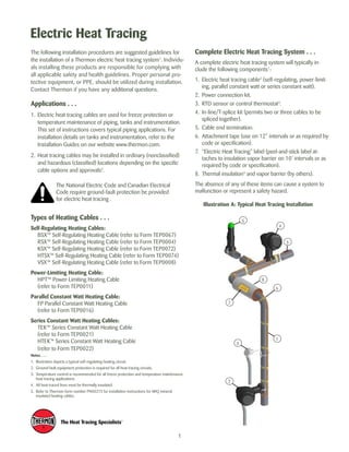
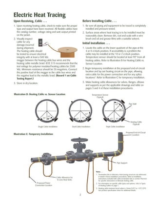
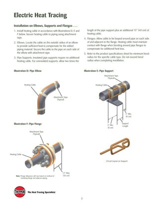
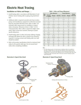
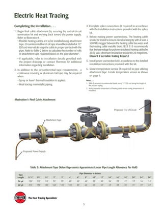
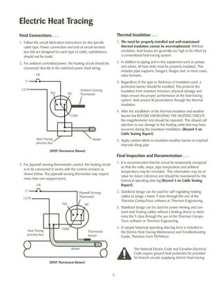
SlideShare a Scribd company logo
Tel: +44 (0)191 490 1547 
Fax: +44 (0)191 477 5371 
Email: northernsales@thorneandderrick.co.uk 
Website: www.heattracing.co.uk 
www.thorneanderrick.co.uk 
Electric Heat Tracing 
INSTALLATION PROCEDURES
Electric Heat Tracing 
The following installation procedures are suggested guidelines for 
the installation of a Thermon electric heat tracing system1. Individu-als 
installing these products are responsible for complying with 
all applicable safety and health guidelines. Proper personal pro-tective 
equipment, or PPE, should be utilized during installation. 
temperature maintenance of piping, tanks and instrumentation. 
This set of instructions covers typical piping applications. For 
installation details on tanks and instrumentation, refer to the 
Installation Guides on our website www.thermon.com. 
2. Heat tracing cables may be installed in ordinary (nonclassified) 
and hazardous (classified) locations depending on the specific 
cable options and approvals2. 
1 
Complete Electric Heat Tracing System . . . 
A complete electric heat tracing system will typically in-clude 
the following components1: 
1. Electric heat tracing cable2 (self-regulating, power-limit-ing, 
parallel constant watt or series constant watt). 
2. Power connection kit. 
3. RTD sensor or control thermostat3. 
4. In-line/T-splice kit (permits two or three cables to be 
spliced together). 
5. Cable end termination. 
6. Attachment tape (use on 12” intervals or as required by 
code or specification). 
7. “Electric Heat Tracing” label (peel-and-stick label at-taches 
to insulation vapor barrier on 10’ intervals or as 
required by code or specification). 
8. Thermal insulation4 and vapor barrier (by others). 
The absence of any of these items can cause a system to 
malfunction or represent a safety hazard. 
Illustration A: Typical Heat Tracing Installation 
Contact Thermon if you have any additional questions. 
Applications . . . 
1. Electric heat tracing cables are used for freeze protection or 
The National Electric Code and Canadian Electrical 
Code require ground-fault protection be provided 
for electric heat tracing . 
Types of Heating Cables . . . 
Self-Regulating Heating Cables: 
BSX™ Self-Regulating Heating Cable (refer to Form TEP0067) 
RSX™ Self-Regulating Heating Cable (refer to Form TEP0004) 
KSX™ Self-Regulating Heating Cable (refer to Form TEP0072) 
HTSX™ Self-Regulating Heating Cable (refer to Form TEP0074) 
VSX™ Self-Regulating Heating Cable (refer to Form TEP0008) 
Power-Limiting Heating Cable: 
HPT™ Power-Limiting Heating Cable 
(refer to Form TEP0011) 
Parallel Constant Watt Heating Cable: 
FP Parallel Constant Watt Heating Cable 
(refer to Form TEP0016) 
Series Constant Watt Heating Cables: 
TEK™ Series Constant Watt Heating Cable 
(refer to Form TEP0021) 
HTEK™ Series Constant Watt Heating Cable 
(refer to Form TEP0022) 
Notes . . . 
1. Illustration depicts a typical self-regulating heating circuit. 
2. Ground-fault equipment protection is required for all heat tracing circuits. 
3. Temperature control is recommended for all freeze protection and temperature maintenance 
heat tracing applications. 
4. All heat-traced lines must be thermally insulated. 
5. Refer to Thermon form number PN50273 for installation instructions for MIQ mineral 
insulated heating cables. 
8 
5 
4 
6 
5 
1 
2 
3 
7
Electric Heat Tracing 
Before Installing Cable . . . 
1. Be sure all piping and equipment to be traced is completely 
installed and pressure tested. 
2. Surface areas where heat tracing is to be installed must be 
reasonably clean. Remove dirt, rust and scale with a wire 
brush and oil and grease films with a suitable solvent. 
Initial Installation . . . 
1. Locate the cable on the lower quadrant of the pipe at the 
4 or 8 o’clock position. If accessibility is a problem the 
cable may be installed at the 10 or 2 o’clock position. 
Temperature sensor should be located at least 90° from all 
heating cables. Refer to Illustration B for Heating Cable vs. 
Sensor Location. 
2. Begin temporary installation at the proposed end-of-circuit 
location and lay out heating circuit on the pipe, allowing 
extra cable for the power connection and for any splice 
locations3. Refer to Illustration C for temporary installation. 
3. Make heating cable allowances for valves, flanges, elbows 
and supports as per the applicable drawings and table on 
pages 3 and 4 of these installation procedures. 
Single Cable Installation Dual Cable Installation Triple Cable Installation 
Pipe Wall 
Illustration C: Temporary Installation Location 
Proposed Power 
Connection Location 
Cable Allowance for 
In-Line Heat Sinks 
Proposed End-of-Circuit 
Pipe Support 
Notes . . . 
1. Termination kits to fabricate a heat tracing circuit are not addressed 
in detail in these installation procedures. Refer to installation 
instructions included with cable termination kits or contact Thermon 
for specific instructions to fabricate heating cable. 
2. For information on specific cable types and options, refer to Types 
of Heating Cables on page 1. 
3. Heating cable minimum bend radius is 10mm (3/8”) at -15°C (5°F). 
See product specification sheet for additional details. 
Upon Receiving, Cable . . . 
1. Upon receiving heating cable, check to make sure the proper 
type and output have been received. All flexible cables have 
the catalog number, voltage rating and watt output printed 
on the jacket. 
2. Visually inspect 
cable for any 
damage incurred 
during shipment. 
The heating cable should 
be tested to ensure electrical 
integrity with at least a 500 Vdc 
megger between the heating cable bus wires and the 
heating cable metallic braid. IEEE 515 recommends that the 
test voltage for polymer insulated heating cables be 2500 
Vdc. Minimum resistance should be 20 megohms. Connect 
the positive lead of the megger to the cable bus wires and 
the negative lead to the metallic braid. (Record 1 on Cable 
Testing Report.) 
3. Store in dry location. 
2 
Heating Cable 
(Typical) 
Temperature Sensor 
(Typical) 
45º 
45º 
45º 45º 45º 
90º 
Illustration B: Heating Cable vs. Sensor Location 
45º 
90º 45º
Electric Heat Tracing 
Circuit Layout on Support 
Illustration D: Pipe Elbow 
Heating Cable 
Illustration E: Pipe Support 
Illustration F: Pipe Flange 
Attachment Tape 
(Typical) 
Support 
Length 
Attachment Tape 
(Typical) 
Heating Cable 
3” Min. 
(8 cm) 
3” Min. 
(8 cm) 
3 
length of the pipe support plus an additional 15” (40 cm) of 
heating cable. 
4. Flanges: Allow cable to be looped around pipe on each side 
of and adjacent to the flange. Heating cable must maintain 
contact with flange when bending around pipe flanges to 
compensate for additional heat loss. 
5. Refer to the product specifications sheet for minimum bend 
radius for the specific cable type. Do not exceed bend 
radius when completing installation. 
Installation on Elbows, Supports and Flanges . . . 
1. Install heating cable in accordance with Illustrations D, E and 
F below. Secure heating cable to piping using attachment 
tape. 
2. Elbows: Locate the cable on the outside radius of an elbow 
to provide sufficient heat to compensate for the added 
piping material. Secure the cable to the pipe on each side of 
the elbow with attachment tape. 
3. Pipe Supports: Insulated pipe supports require no additional 
heating cable. For uninsulated supports, allow two times the 
Attachment Tape 
(Typical) 
Heating Cable 
12” Max. 
Note: Flange allowance will vary based on method of (30 cm) 
insulating flange and adjacent piping.
Electric Heat Tracing 
Heating Cable 
Pipe 
Size 
Valve Allowance Pump Allowance 
Attachment Tape Heating Cable Serpentined on Pump 
Heating Cable Serpentined on Valve 
Circuit Layout on Pump 
(Typical) 
Heating Cable 
Attachment Tape 
(Typical) 
Circuit Layout on Valve 
4 
Installation on Valves and Pumps . . . 
1. Install heating cable in accordance with Illustrations G and 
H below. Secure heating cable to piping using attachment 
tape. 
2. Additional cable is required to provide extra heat at valves, 
pumps and miscellaneous equipment to offset the increased 
heat loss associated with these items. Refer to Table 1 for 
estimated cable requirements for installation on typical 
valves and pumps. Allowances shown in Table 1 are for 
150 pound valves. More cable is required for higher rated 
valves. Refer to heat trace isometric drawing for project 
specific allowances. 
3. Install heating cable on valves and pumps utilizing a looping 
technique (this allows the valve or pump to be removed if 
required). Crossing constant watt heating cable over itself 
should be avoided. 
4. Refer to the product specifications sheet for minimum bend 
radius for the specific cable type. Do not exceed bend 
radius when completing installation. 
Table 1: Valve and Pump Allowances1 
Illustration G: Typical Valve Detail Illustration H: Typical Pump Detail 
Flange 
Screwed Allowance 
or Welded Flanged Butterfly Screwed Flanged 
½" 6" 1' 0 1' 2' 1’ 3" 
¾" 9" 1' 6" 0 1' 6" 3' 1’ 6" 
1" 1' 2' 1' 2' 4' 1’ 6” 
1¼" 1' 6" 2' 1' 3' 4' 6" 2’ 0" 
1½" 1' 6" 2' 6" 1' 6" 3' 5' 2’ 0" 
2" 2' 2' 6" 2' 4' 5' 6" 2’ 3" 
3" 2' 6" 3' 6" 2' 6" 5' 7' 2’ 3" 
4" 4' 5' 3' 8' 10' 2’ 9" 
6" 7' 8' 3' 6" 14' 16' 3’ 3" 
8" 9' 6" 11' 4' 19' 22' 3’ 9" 
10" 12' 6" 14' 4' 25' 28' 4’ 3" 
12" 15' 16' 6" 5' 30' 33' 5’ 0" 
14" 18' 19' 6" 5' 6" 36' 39' 5’ 6" 
16" 21' 6" 23' 6' 43' 46' 6’ 0" 
18" 25' 6" 27' 6' 6" 51' 54' 6’ 6" 
20" 28' 6" 30' 7' 57' 60' 7’ 3" 
24" 34' 36' 8' 68' 72' 8’ 3" 
30" 40' 42' 10' 80' 84' 10’ 0" 
Note . . . 
1. The valve allowance given is the total amount of additional cable to be installed on 
the valve. If multiple tracers are used, total valve allowance may be divided among 
the individual tracers. The total valve allowance may be alternated among tracers for 
multiple valves in a heat trace circuit. Allowances are for 150 pound valves. More cable 
is required for higher rated valves. Refer to heat trace isometric drawing for project 
specific allowances.
Electric Heat Tracing 
5 
Completing the Installation . . . 
1. Begin final cable attachment by securing the end-of-circuit 
termination kit and working back toward the power supply. 
Refer to Illustration I. 
• Flexible heating cables are to be installed using attachment 
tape. Circumferential bands of tape should be installed at 12” 
(30 cm) intervals to keep the cable in proper contact with the 
pipe. Refer to Table 2 below to calculate the number of rolls 
of attachment tape required based on the pipe diameter1. 
• If applicable, refer to installation details provided with 
the project drawings or contact Thermon for additional 
information regarding installation. 
2. In addition to the circumferential tape requirements, a 
continuous covering of aluminum foil tape may be required 
when: 
• Spray or foam2 thermal insulation is applied. 
• Heat tracing nonmetallic piping. 
3. Complete splice connections (if required) in accordance 
with the installation instructions provided with the splice 
kit. 
4. Before making power connections, The heating cable 
should be tested to ensure electrical integrity with at least a 
500 Vdc megger between the heating cable bus wires and 
the heating cable metallic braid. IEEE 515 recommends 
that the test voltage for polymer insulated heating cables be 
2500 Vdc. Minimum resistance should be 20 megohms. 
(Record 2 on Cable Testing Report.) 
5. Install power connection kit in accordance to the detailed 
installation instructions provided with the kit. 
6. Secure temperature sensor (if required) to pipe utilizing 
attachment tape. Locate temperature sensor as shown 
on page 6. 
Notes . . . 
1. Table 2 assumes circumferential bands every 12” (30 cm) along the length of 
the process piping. 
2. Verify exposure temperature of heating cable versus curing temperature of 
insulation. 
Illustration I: Final Cable Attachment 
Proposed End of Circuit 
Attachment Tape 
Proposed Power Supply 
Table 2: Attachment Tape (Value Represents Approximate Linear Pipe Length Allowance Per Roll) 
Tape 
Length 
Pipe Diameter in Inches 
½"-1" 1¼" 1½" 2" 3" 4" 6" 8" 10" 12" 14" 16" 18" 20" 24" 30" 
36 yd 130' 115' 110' 95' 75' 65' 50' 40' 35' 30' 26' 23' 21' 19' 16' 13' 
60 yd 215' 195' 180' 160' 125' 105' 80' 65' 55' 50' 43' 38' 35' 31' 27' 22'
Electric Heat Tracing 
6 
Thermal Insulation . . . 
1. The need for properly installed and well-maintained 
thermal insulation cannot be overemphasized. Without 
insulation, heat losses are generally too high to be offset by 
a conventional heat tracing system. 
2. In addition to piping and in-line equipment such as pumps 
and valves, all heat sinks must be properly insulated. This 
includes pipe supports, hangers, flanges and, in most cases, 
valve bonnets. 
3. Regardless of the type or thickness of insulation used, a 
protective barrier should be installed. This protects the 
insulation from moisture intrusion, physical damage and 
helps ensure the proper performance of the heat tracing 
system. Seal around all penetrations through the thermal 
insulation. 
4. After the installation of the thermal insulation and weather 
barrier but BEFORE ENERGIZING THE HEATING CIRCUIT, 
the megohmmeter test should be repeated. This should call 
attention to any damage to the heating cable that may have 
occurred during the insulation installation. (Record 3 on 
Cable Testing Report) 
5. Apply caution labels to insulation weather barrier at required 
intervals along pipe 
Final Inspection and Documentation . . . 
1. It is recommended that the circuit be temporarily energized 
so that the volts, amps, pipe temperature and ambient 
temperature may be recorded. This information may be of 
value for future reference and should be maintained for the 
historical operating data log (Record 4 on Cable Testing 
Report). 
2. Stabilized design can be used for self-regulating heating 
cables to assign a lower T-class through the use of the 
Thermon CompuTrace software or Thermon Engineering. 
3. Stabilized design can be used for power-limiting and con-stant 
watt heating cables without a limiting device to deter-mine 
the T-class through the use of the Thermon Compu- 
Trace software or Thermon Engineering. 
4. A sample historical operating data log form is included in 
the Electric Heat Tracing Maintenance and Troubleshooting 
Guide, Thermon Form TEP0066). 
Final Connections . . . 
1. Follow the circuit fabrication instructions for the specific 
cable type. Power connection and end-of-circuit termina-tion 
kits are designed for each type of cable; substitutions 
should not be made. 
2. For ambient controlled power, the heating circuit should be 
connected directly to the switched power feed wiring. 
L2/N Ambient Sensing 
NO NC 
(SPDT Thermostat Shown) 
3. For pipewall sensing thermostatic control, the heating circuit 
is to be connected in series with the control contacts as 
shown below. The pipewall sensing thermostat may require 
more than one support point. 
The National Electric Code and Canadian Electrical 
Code require ground-fault protection be provided 
for branch circuits supplying electric heat tracing. 
L1 
Heat Tracing 
Junction Box 
Thermostat 
CB 
COM 
Heater 
L1 
L2/N 
Heat Tracing 
Junction Box 
Pipewall Sensing 
Thermostat 
CB 
NO NC 
Thermostat 
Sensor 
COM 
Heater 
(SPDT Thermostat Shown)
Cable Testing Report 
1. Refer to Thermon Installation Procedures, FORM PN 50207, for general installation procedures, requirements and guidelines. 
2. Upon receiving heating cable, check the cable to make sure the proper type and output have been received. All flexible cables 
have the catalog number, voltage rating and watt output printed on the outer jacket. 
3. Visually inspect cable for any damage incurred during shipment. The heating cable should be tested to ensure electrical integrity 
with at least a 500 Vdc megger between the heating cable bus wires and the heating cable metallic braid. 
IEEE 515 recommends that the test voltage for polymer insulated heating cables be 2500 Vdc. Minimum resistance should be 
20 megohms. (Record 1 on Cable Testing Report.) 
A. Connect the positive lead of the megger to the cable bus wires. 
B. Connect the negative lead of the megger to the metallic braid. 
C. Energize the megger and record the reading. Readings between 
20 megohms and infinity are acceptable. Readings below 20 
megohms may mean the electrical insulation has been dam-aged. 
Recheck the heating cable for physical damage between 
the braid and the heating element; small cuts or scuffmarks on 
the outer jacket will not affect the megger reading unless there was actual penetration through the braid and dielectric insula-tion 
jacket. 
4. Once the installation is complete, but prior to installation of thermal insulation, recheck the heating cable with at least a 500 Vdc 
megger between the heating cable bus wires and the heating cable metallic braid. IEEE 515 recommends that the test voltage 
for polymer insulated heating cables be 2500 Vdc should be 20 megohms. (Record 2 on Cable Testing Report.) 
5. After the thermal insulation is installed, the megohmmeter test should be repeated. Minimum resistance should be 5 megohms. 
(Record 3 on Cable Testing Report.) 
6. After the thermal insulation is installed and power supply is completed, record the panel and circuit breaker information. Ensure 
all junction boxes, temperature controllers, cable glands, etc. are properly secured. Set the temperature controller (if appli-cable) 
to the manual setting and apply rated voltage to the heat tracing circuit(s) for 5 minutes. Record the ambient temperature, 
measure and record the circuit(s) voltage and current. (Record 4 on Cable Testing Report.) 
NOTE: To ensure the heating cable warranty is maintained through installation, the testing outlined on 
this sheet must be completed on the installed heating cables, and the test results recorded and 
mailed/faxed to: 
Thermon Customer Service 
100 Thermon Drive 
San Marcos, Texas 78666 
Fax: 512-754-2420 
7
Cable Testing Report 
make additional copies as required for each circuit. 
Customer: Contractor: 
Address: Address: 
Phone No: Phone No. 
Project Reference: 
Record 1: Prior to Installation 
Cable Type: 
Reel Length: 
Reel Number: 
Insulation Resistance M Ohms: 
Tested By: Date: 
Witnessed By: Date: 
Record 2: After Installation of Heating Cable 
Insulation Resistance M Ohms: 
Heater Length: 
Heater Number: 
Tested By: Date: 
Witnessed By: Date: 
Record 3: After The Thermal Insulation Is Installed 
Insulation Resistance M Ohms: 
Tested By: Date: 
Witnessed By: Date: 
Record 4: Final Commissioning 
Panel Number: 
Breaker Number: 
Volts: 
Ambient Temperature (deg. F): 
Pipe Temperature (deg. F): 
Recorded Amps (After 5 Min.): 
Tested By: Date: 
Witnessed By: Date: 
8
For the Thermon office nearest you 
visit us at . . . 
www.thermon.com 
THERMON . . . The Heat Tracing Specialists® 
100 Thermon Dr. • PO Box 609 • San Marcos, TX 78667-0609 
Phone: 512-396-5801 • Facsimile: 512-396-3627 
1-800-820-HEAT • In Canada call 1-800-563-8461 
Specifications and information are subject to change without notice. Form PN50207-1111 
Tel: +44 (0)191 490 1547 
Fax: +44 (0)191 477 5371 
Email: northernsales@thorneandderrick.co.uk 
Website: www.heattracing.co.uk 
www.thorneanderrick.co.uk

More Related Content

What's hot

Piping training-course
Piping training-coursePiping training-course
Piping training-course
pdmsguy
 
Flange types
Flange typesFlange types
Flange types
Hieu Dang
 
Heat Treatment
Heat TreatmentHeat Treatment
Heat Treatment
Rami Al-Majzoub
 
Selection of Valves
Selection of ValvesSelection of Valves
Selection of Valves
SivaSubramanian Sakthivel
 
Heat tracing installation by Thermon
Heat tracing installation by ThermonHeat tracing installation by Thermon
Heat tracing installation by Thermon
Carotek
 
Welding electrode
Welding electrodeWelding electrode
Welding electrode
KabilManekandan
 
Welding electrodes Classification & baking
Welding electrodes Classification &  bakingWelding electrodes Classification &  baking
Welding electrodes Classification & baking
Weld Maniac
 
Contents sre cable tray
Contents sre cable trayContents sre cable tray
Contents sre cable tray
S.R.ELECTRICAL CO. BEAWAR
 
Caeser II manual
Caeser II manualCaeser II manual
Caeser II manual
Somesh Angle
 
Walk-Through Pipe Stress.pdf
Walk-Through Pipe Stress.pdfWalk-Through Pipe Stress.pdf
Walk-Through Pipe Stress.pdf
ashish123sati
 
criteria of weld defects
criteria of weld defects criteria of weld defects
criteria of weld defects
Saqib Rasool
 
Heat Exchangers inspection .pdf
Heat Exchangers inspection .pdfHeat Exchangers inspection .pdf
Heat Exchangers inspection .pdf
NickeshShah
 
Asme b31.3 process_piping
Asme b31.3 process_pipingAsme b31.3 process_piping
Asme b31.3 process_piping
dinusim
 
Welding flaws
Welding flawsWelding flaws
Welding flaws
Jithu John
 
How to produce PQR
How to produce PQRHow to produce PQR
How to produce PQR
Mohamed Farouk
 
RAYCHEM TERMINATION KIT-TYCO TERMINATION-케이블 종단-거-瑞侃工具包电缆终端-阿克巴交易
RAYCHEM TERMINATION KIT-TYCO TERMINATION-케이블 종단-거-瑞侃工具包电缆终端-阿克巴交易RAYCHEM TERMINATION KIT-TYCO TERMINATION-케이블 종단-거-瑞侃工具包电缆终端-阿克巴交易
RAYCHEM TERMINATION KIT-TYCO TERMINATION-케이블 종단-거-瑞侃工具包电缆终端-阿克巴交易
AKBAR TRADING
 
Wis5 welding defects 02
Wis5 welding defects 02Wis5 welding defects 02
Wis5 welding defects 02
Thang Do Minh
 
Pwht1
Pwht1Pwht1
Pwht1
Jithu John
 
Piping Training course-How to be an Expert in Pipe & Fittings for Oil & Gas c...
Piping Training course-How to be an Expert in Pipe & Fittings for Oil & Gas c...Piping Training course-How to be an Expert in Pipe & Fittings for Oil & Gas c...
Piping Training course-How to be an Expert in Pipe & Fittings for Oil & Gas c...
Varun Patel
 

What's hot (20)

Piping training-course
Piping training-coursePiping training-course
Piping training-course
 
Flange types
Flange typesFlange types
Flange types
 
Heat Treatment
Heat TreatmentHeat Treatment
Heat Treatment
 
Selection of Valves
Selection of ValvesSelection of Valves
Selection of Valves
 
Heat tracing installation by Thermon
Heat tracing installation by ThermonHeat tracing installation by Thermon
Heat tracing installation by Thermon
 
Welding electrode
Welding electrodeWelding electrode
Welding electrode
 
Welding electrodes Classification & baking
Welding electrodes Classification &  bakingWelding electrodes Classification &  baking
Welding electrodes Classification & baking
 
Contents sre cable tray
Contents sre cable trayContents sre cable tray
Contents sre cable tray
 
Caeser II manual
Caeser II manualCaeser II manual
Caeser II manual
 
Walk-Through Pipe Stress.pdf
Walk-Through Pipe Stress.pdfWalk-Through Pipe Stress.pdf
Walk-Through Pipe Stress.pdf
 
criteria of weld defects
criteria of weld defects criteria of weld defects
criteria of weld defects
 
Heat Exchangers inspection .pdf
Heat Exchangers inspection .pdfHeat Exchangers inspection .pdf
Heat Exchangers inspection .pdf
 
Asme b31.3 process_piping
Asme b31.3 process_pipingAsme b31.3 process_piping
Asme b31.3 process_piping
 
Welding flaws
Welding flawsWelding flaws
Welding flaws
 
How to produce PQR
How to produce PQRHow to produce PQR
How to produce PQR
 
Flange
FlangeFlange
Flange
 
RAYCHEM TERMINATION KIT-TYCO TERMINATION-케이블 종단-거-瑞侃工具包电缆终端-阿克巴交易
RAYCHEM TERMINATION KIT-TYCO TERMINATION-케이블 종단-거-瑞侃工具包电缆终端-阿克巴交易RAYCHEM TERMINATION KIT-TYCO TERMINATION-케이블 종단-거-瑞侃工具包电缆终端-阿克巴交易
RAYCHEM TERMINATION KIT-TYCO TERMINATION-케이블 종단-거-瑞侃工具包电缆终端-阿克巴交易
 
Wis5 welding defects 02
Wis5 welding defects 02Wis5 welding defects 02
Wis5 welding defects 02
 
Pwht1
Pwht1Pwht1
Pwht1
 
Piping Training course-How to be an Expert in Pipe & Fittings for Oil & Gas c...
Piping Training course-How to be an Expert in Pipe & Fittings for Oil & Gas c...Piping Training course-How to be an Expert in Pipe & Fittings for Oil & Gas c...
Piping Training course-How to be an Expert in Pipe & Fittings for Oil & Gas c...
 

Viewers also liked

HEATFAST HF9101-v1 Ambient Sensing Heat Tracing Thermostat - Spec Sheet
HEATFAST HF9101-v1 Ambient Sensing Heat Tracing Thermostat - Spec SheetHEATFAST HF9101-v1 Ambient Sensing Heat Tracing Thermostat - Spec Sheet
HEATFAST HF9101-v1 Ambient Sensing Heat Tracing Thermostat - Spec Sheet
Thorne & Derrick UK
 
Heatfast HF1210 Heat Tracing Cable - Spec Sheet
Heatfast HF1210 Heat Tracing Cable - Spec SheetHeatfast HF1210 Heat Tracing Cable - Spec Sheet
Heatfast HF1210 Heat Tracing Cable - Spec Sheet
Thorne & Derrick UK
 
Winter Frost Protection Trace Heating Kit Heatfast HF7005 - Spec Sheet
Winter Frost Protection Trace Heating Kit Heatfast HF7005 - Spec SheetWinter Frost Protection Trace Heating Kit Heatfast HF7005 - Spec Sheet
Winter Frost Protection Trace Heating Kit Heatfast HF7005 - Spec SheetThorne & Derrick UK
 
PP10 startup manual (Unofficial as Requested)
PP10 startup manual (Unofficial as Requested)PP10 startup manual (Unofficial as Requested)
PP10 startup manual (Unofficial as Requested)Muhammad Gulzar
 
Heat Tracing - Fire Protection Association's RC38 Recommendation for Frost Pr...
Heat Tracing - Fire Protection Association's RC38 Recommendation for Frost Pr...Heat Tracing - Fire Protection Association's RC38 Recommendation for Frost Pr...
Heat Tracing - Fire Protection Association's RC38 Recommendation for Frost Pr...
Thorne & Derrick UK
 
Silver Fox Cable Labelling And Marking Product Catalogue 2015
Silver Fox Cable Labelling And Marking Product Catalogue 2015Silver Fox Cable Labelling And Marking Product Catalogue 2015
Silver Fox Cable Labelling And Marking Product Catalogue 2015
Thorne & Derrick International
 
Thermon MIQ Heat Tracing Cable - Spec Sheet
Thermon MIQ Heat Tracing Cable - Spec SheetThermon MIQ Heat Tracing Cable - Spec Sheet
Thermon MIQ Heat Tracing Cable - Spec Sheet
Thorne & Derrick UK
 
Thermon RGS Heat Tracing Cable - Spec Sheet
Thermon RGS Heat Tracing Cable - Spec SheetThermon RGS Heat Tracing Cable - Spec Sheet
Thermon RGS Heat Tracing Cable - Spec Sheet
Thorne & Derrick UK
 
Thermon HTSX 12-2 Heat Tracing Cable - Spec Sheet
Thermon HTSX 12-2 Heat Tracing Cable - Spec SheetThermon HTSX 12-2 Heat Tracing Cable - Spec Sheet
Thermon HTSX 12-2 Heat Tracing Cable - Spec Sheet
Thorne & Derrick UK
 
Trace Heating Cables Self Regulating - Installation Manual
Trace Heating Cables Self Regulating - Installation ManualTrace Heating Cables Self Regulating - Installation Manual
Trace Heating Cables Self Regulating - Installation ManualThorne & Derrick UK
 
Thermon KSR-2 Heat Tracing Cable - Spec Sheet
Thermon KSR-2 Heat Tracing Cable - Spec SheetThermon KSR-2 Heat Tracing Cable - Spec Sheet
Thermon KSR-2 Heat Tracing Cable - Spec SheetThorne & Derrick UK
 
Heatfast HF9225 Heat Tracing Junction Box - Spec Sheet
Heatfast HF9225 Heat Tracing Junction Box - Spec SheetHeatfast HF9225 Heat Tracing Junction Box - Spec Sheet
Heatfast HF9225 Heat Tracing Junction Box - Spec Sheet
Thorne & Derrick UK
 
Isopad Flexible Heated Hoses, Gas Analyser Hose, Heavy Oil Transfer Hoses & B...
Isopad Flexible Heated Hoses, Gas Analyser Hose, Heavy Oil Transfer Hoses & B...Isopad Flexible Heated Hoses, Gas Analyser Hose, Heavy Oil Transfer Hoses & B...
Isopad Flexible Heated Hoses, Gas Analyser Hose, Heavy Oil Transfer Hoses & B...Thorne & Derrick UK
 
Hot Water Heat Tracing - Maintenance and Troubleshooting Guide
Hot Water Heat Tracing - Maintenance and Troubleshooting GuideHot Water Heat Tracing - Maintenance and Troubleshooting Guide
Hot Water Heat Tracing - Maintenance and Troubleshooting Guide
Thorne & Derrick UK
 
Exheat Flameproof Hazardous Area Heaters, Zone 1 & Zone 2 - Brochure
Exheat Flameproof Hazardous Area Heaters, Zone 1 & Zone 2 - BrochureExheat Flameproof Hazardous Area Heaters, Zone 1 & Zone 2 - Brochure
Exheat Flameproof Hazardous Area Heaters, Zone 1 & Zone 2 - BrochureThorne & Derrick UK
 
Hadar Lighting - Hazardous Area Zone 1 & Zone 2 Lighting (ATEX Certified)
Hadar Lighting - Hazardous Area Zone 1 & Zone 2 Lighting (ATEX Certified)Hadar Lighting - Hazardous Area Zone 1 & Zone 2 Lighting (ATEX Certified)
Hadar Lighting - Hazardous Area Zone 1 & Zone 2 Lighting (ATEX Certified)
Thorne & Derrick International
 
Roxtec Cable And Pipe Transits - Product Selection And Application Checklist
Roxtec Cable And Pipe Transits - Product Selection And Application ChecklistRoxtec Cable And Pipe Transits - Product Selection And Application Checklist
Roxtec Cable And Pipe Transits - Product Selection And Application Checklist
Thorne & Derrick International
 
Nexans Euromold Connectors 400 Series Interface C Symmetrical Cable Connector...
Nexans Euromold Connectors 400 Series Interface C Symmetrical Cable Connector...Nexans Euromold Connectors 400 Series Interface C Symmetrical Cable Connector...
Nexans Euromold Connectors 400 Series Interface C Symmetrical Cable Connector...
Thorne & Derrick International
 
Prysmian Draka - Oil, Marine & Gas Cable Presentation
Prysmian Draka - Oil, Marine & Gas Cable PresentationPrysmian Draka - Oil, Marine & Gas Cable Presentation
Prysmian Draka - Oil, Marine & Gas Cable Presentation
Thorne & Derrick International
 

Viewers also liked (20)

HEATFAST HF9101-v1 Ambient Sensing Heat Tracing Thermostat - Spec Sheet
HEATFAST HF9101-v1 Ambient Sensing Heat Tracing Thermostat - Spec SheetHEATFAST HF9101-v1 Ambient Sensing Heat Tracing Thermostat - Spec Sheet
HEATFAST HF9101-v1 Ambient Sensing Heat Tracing Thermostat - Spec Sheet
 
Heatfast HF1210 Heat Tracing Cable - Spec Sheet
Heatfast HF1210 Heat Tracing Cable - Spec SheetHeatfast HF1210 Heat Tracing Cable - Spec Sheet
Heatfast HF1210 Heat Tracing Cable - Spec Sheet
 
Winter Frost Protection Trace Heating Kit Heatfast HF7005 - Spec Sheet
Winter Frost Protection Trace Heating Kit Heatfast HF7005 - Spec SheetWinter Frost Protection Trace Heating Kit Heatfast HF7005 - Spec Sheet
Winter Frost Protection Trace Heating Kit Heatfast HF7005 - Spec Sheet
 
PP10 startup manual (Unofficial as Requested)
PP10 startup manual (Unofficial as Requested)PP10 startup manual (Unofficial as Requested)
PP10 startup manual (Unofficial as Requested)
 
Heat Tracing - Fire Protection Association's RC38 Recommendation for Frost Pr...
Heat Tracing - Fire Protection Association's RC38 Recommendation for Frost Pr...Heat Tracing - Fire Protection Association's RC38 Recommendation for Frost Pr...
Heat Tracing - Fire Protection Association's RC38 Recommendation for Frost Pr...
 
Silver Fox Cable Labelling And Marking Product Catalogue 2015
Silver Fox Cable Labelling And Marking Product Catalogue 2015Silver Fox Cable Labelling And Marking Product Catalogue 2015
Silver Fox Cable Labelling And Marking Product Catalogue 2015
 
Thermon MIQ Heat Tracing Cable - Spec Sheet
Thermon MIQ Heat Tracing Cable - Spec SheetThermon MIQ Heat Tracing Cable - Spec Sheet
Thermon MIQ Heat Tracing Cable - Spec Sheet
 
Thermon RGS Heat Tracing Cable - Spec Sheet
Thermon RGS Heat Tracing Cable - Spec SheetThermon RGS Heat Tracing Cable - Spec Sheet
Thermon RGS Heat Tracing Cable - Spec Sheet
 
Thermon HTSX 12-2 Heat Tracing Cable - Spec Sheet
Thermon HTSX 12-2 Heat Tracing Cable - Spec SheetThermon HTSX 12-2 Heat Tracing Cable - Spec Sheet
Thermon HTSX 12-2 Heat Tracing Cable - Spec Sheet
 
Trace Heating Cables Self Regulating - Installation Manual
Trace Heating Cables Self Regulating - Installation ManualTrace Heating Cables Self Regulating - Installation Manual
Trace Heating Cables Self Regulating - Installation Manual
 
Ashcroft Inc - Product Overview
Ashcroft Inc - Product OverviewAshcroft Inc - Product Overview
Ashcroft Inc - Product Overview
 
Thermon KSR-2 Heat Tracing Cable - Spec Sheet
Thermon KSR-2 Heat Tracing Cable - Spec SheetThermon KSR-2 Heat Tracing Cable - Spec Sheet
Thermon KSR-2 Heat Tracing Cable - Spec Sheet
 
Heatfast HF9225 Heat Tracing Junction Box - Spec Sheet
Heatfast HF9225 Heat Tracing Junction Box - Spec SheetHeatfast HF9225 Heat Tracing Junction Box - Spec Sheet
Heatfast HF9225 Heat Tracing Junction Box - Spec Sheet
 
Isopad Flexible Heated Hoses, Gas Analyser Hose, Heavy Oil Transfer Hoses & B...
Isopad Flexible Heated Hoses, Gas Analyser Hose, Heavy Oil Transfer Hoses & B...Isopad Flexible Heated Hoses, Gas Analyser Hose, Heavy Oil Transfer Hoses & B...
Isopad Flexible Heated Hoses, Gas Analyser Hose, Heavy Oil Transfer Hoses & B...
 
Hot Water Heat Tracing - Maintenance and Troubleshooting Guide
Hot Water Heat Tracing - Maintenance and Troubleshooting GuideHot Water Heat Tracing - Maintenance and Troubleshooting Guide
Hot Water Heat Tracing - Maintenance and Troubleshooting Guide
 
Exheat Flameproof Hazardous Area Heaters, Zone 1 & Zone 2 - Brochure
Exheat Flameproof Hazardous Area Heaters, Zone 1 & Zone 2 - BrochureExheat Flameproof Hazardous Area Heaters, Zone 1 & Zone 2 - Brochure
Exheat Flameproof Hazardous Area Heaters, Zone 1 & Zone 2 - Brochure
 
Hadar Lighting - Hazardous Area Zone 1 & Zone 2 Lighting (ATEX Certified)
Hadar Lighting - Hazardous Area Zone 1 & Zone 2 Lighting (ATEX Certified)Hadar Lighting - Hazardous Area Zone 1 & Zone 2 Lighting (ATEX Certified)
Hadar Lighting - Hazardous Area Zone 1 & Zone 2 Lighting (ATEX Certified)
 
Roxtec Cable And Pipe Transits - Product Selection And Application Checklist
Roxtec Cable And Pipe Transits - Product Selection And Application ChecklistRoxtec Cable And Pipe Transits - Product Selection And Application Checklist
Roxtec Cable And Pipe Transits - Product Selection And Application Checklist
 
Nexans Euromold Connectors 400 Series Interface C Symmetrical Cable Connector...
Nexans Euromold Connectors 400 Series Interface C Symmetrical Cable Connector...Nexans Euromold Connectors 400 Series Interface C Symmetrical Cable Connector...
Nexans Euromold Connectors 400 Series Interface C Symmetrical Cable Connector...
 
Prysmian Draka - Oil, Marine & Gas Cable Presentation
Prysmian Draka - Oil, Marine & Gas Cable PresentationPrysmian Draka - Oil, Marine & Gas Cable Presentation
Prysmian Draka - Oil, Marine & Gas Cable Presentation
 

Similar to Electric Heat Tracing - Installation Procedures (Thermon Cables)

Trace Heating Series Constant Wattage Trace Heating Cables
Trace Heating Series Constant Wattage Trace Heating CablesTrace Heating Series Constant Wattage Trace Heating Cables
Trace Heating Series Constant Wattage Trace Heating CablesThorne & Derrick UK
 
Frost Protection Heat Tracing - Frost Protection Installation Procedures
Frost Protection Heat Tracing - Frost Protection Installation ProceduresFrost Protection Heat Tracing - Frost Protection Installation Procedures
Frost Protection Heat Tracing - Frost Protection Installation Procedures
Thorne & Derrick UK
 
Frost Protection Heat Tracing - Frost Protection Installation Procedures
Frost Protection Heat Tracing - Frost Protection Installation ProceduresFrost Protection Heat Tracing - Frost Protection Installation Procedures
Frost Protection Heat Tracing - Frost Protection Installation Procedures
Thorne & Derrick UK
 
Hot Water Temperature Maintenance Heat Tracing - Planning Instructions
Hot Water Temperature Maintenance Heat Tracing - Planning InstructionsHot Water Temperature Maintenance Heat Tracing - Planning Instructions
Hot Water Temperature Maintenance Heat Tracing - Planning Instructions
Thorne & Derrick UK
 
SunMaxx Installation Manual - StorMaxx Solar Hot Water Storage Tanks
SunMaxx Installation Manual - StorMaxx Solar Hot Water Storage TanksSunMaxx Installation Manual - StorMaxx Solar Hot Water Storage Tanks
SunMaxx Installation Manual - StorMaxx Solar Hot Water Storage Tanks
SunMaxx Solar
 
Thermon BSX Self-Regulating Heating Cable
Thermon BSX Self-Regulating Heating CableThermon BSX Self-Regulating Heating Cable
Thermon BSX Self-Regulating Heating Cable
Thorne & Derrick International
 
wireless-thermostat-v2-installation-guide-rev-f.pdf
wireless-thermostat-v2-installation-guide-rev-f.pdfwireless-thermostat-v2-installation-guide-rev-f.pdf
wireless-thermostat-v2-installation-guide-rev-f.pdf
JuanRiquelmeHerrera
 
Service ariston kelapa gading 0813-8024-0365
Service ariston kelapa gading 0813-8024-0365Service ariston kelapa gading 0813-8024-0365
Service ariston kelapa gading 0813-8024-0365
komporariston
 
Instalasi water heater 081313462267
Instalasi water heater 081313462267Instalasi water heater 081313462267
Instalasi water heater 081313462267
pasangwaterheater
 
Service ariston serpong 0813-8024-0365
Service ariston serpong 0813-8024-0365Service ariston serpong 0813-8024-0365
Service ariston serpong 0813-8024-0365
komporariston
 
Heat tracing ppt
Heat tracing pptHeat tracing ppt
Heat tracing ppt
Er Ramgarhia
 
Thermon tesh-2-9-trace-heating-cable---spec-sheet
Thermon tesh-2-9-trace-heating-cable---spec-sheetThermon tesh-2-9-trace-heating-cable---spec-sheet
Thermon tesh-2-9-trace-heating-cable---spec-sheetThorne & Derrick UK
 
Thermon TESH 10 Heat Tracing Cable - Spec Sheet
Thermon TESH 10 Heat Tracing Cable - Spec SheetThermon TESH 10 Heat Tracing Cable - Spec Sheet
Thermon TESH 10 Heat Tracing Cable - Spec Sheet
Thorne & Derrick UK
 
Thermon TESH 2.9 Heat Tracing Cable Spec Sheet
Thermon TESH 2.9 Heat Tracing Cable Spec SheetThermon TESH 2.9 Heat Tracing Cable Spec Sheet
Thermon TESH 2.9 Heat Tracing Cable Spec Sheet
Thorne & Derrick UK
 
Thermon TESH Heat Tracing Cable - Spec Sheet
Thermon TESH Heat Tracing Cable - Spec SheetThermon TESH Heat Tracing Cable - Spec Sheet
Thermon TESH Heat Tracing Cable - Spec Sheet
Thorne & Derrick UK
 
Thermon TESH 4.4 Heat Tracing Cable - Spec Sheet
Thermon TESH 4.4 Heat Tracing Cable - Spec SheetThermon TESH 4.4 Heat Tracing Cable - Spec Sheet
Thermon TESH 4.4 Heat Tracing Cable - Spec Sheet
Thorne & Derrick UK
 
Thermon TESH 7 Heat Tracing Cable - Spec Sheet
Thermon TESH 7 Heat Tracing Cable - Spec SheetThermon TESH 7 Heat Tracing Cable - Spec Sheet
Thermon TESH 7 Heat Tracing Cable - Spec Sheet
Thorne & Derrick UK
 
Nelson Heat Tracing Cables - Product Catalogue
Nelson Heat Tracing Cables - Product CatalogueNelson Heat Tracing Cables - Product Catalogue
Nelson Heat Tracing Cables - Product Catalogue
Thorne & Derrick UK
 
Thermon MIQ-60E1H-2S Heat Tracing Cable - Spec Sheet
Thermon MIQ-60E1H-2S Heat Tracing Cable - Spec SheetThermon MIQ-60E1H-2S Heat Tracing Cable - Spec Sheet
Thermon MIQ-60E1H-2S Heat Tracing Cable - Spec Sheet
Thorne & Derrick UK
 
Thermon MIQ-11E0H-2S Heat Tracing Cable - Spec Sheet
Thermon MIQ-11E0H-2S Heat Tracing Cable - Spec SheetThermon MIQ-11E0H-2S Heat Tracing Cable - Spec Sheet
Thermon MIQ-11E0H-2S Heat Tracing Cable - Spec Sheet
Thorne & Derrick UK
 

Similar to Electric Heat Tracing - Installation Procedures (Thermon Cables) (20)

Trace Heating Series Constant Wattage Trace Heating Cables
Trace Heating Series Constant Wattage Trace Heating CablesTrace Heating Series Constant Wattage Trace Heating Cables
Trace Heating Series Constant Wattage Trace Heating Cables
 
Frost Protection Heat Tracing - Frost Protection Installation Procedures
Frost Protection Heat Tracing - Frost Protection Installation ProceduresFrost Protection Heat Tracing - Frost Protection Installation Procedures
Frost Protection Heat Tracing - Frost Protection Installation Procedures
 
Frost Protection Heat Tracing - Frost Protection Installation Procedures
Frost Protection Heat Tracing - Frost Protection Installation ProceduresFrost Protection Heat Tracing - Frost Protection Installation Procedures
Frost Protection Heat Tracing - Frost Protection Installation Procedures
 
Hot Water Temperature Maintenance Heat Tracing - Planning Instructions
Hot Water Temperature Maintenance Heat Tracing - Planning InstructionsHot Water Temperature Maintenance Heat Tracing - Planning Instructions
Hot Water Temperature Maintenance Heat Tracing - Planning Instructions
 
SunMaxx Installation Manual - StorMaxx Solar Hot Water Storage Tanks
SunMaxx Installation Manual - StorMaxx Solar Hot Water Storage TanksSunMaxx Installation Manual - StorMaxx Solar Hot Water Storage Tanks
SunMaxx Installation Manual - StorMaxx Solar Hot Water Storage Tanks
 
Thermon BSX Self-Regulating Heating Cable
Thermon BSX Self-Regulating Heating CableThermon BSX Self-Regulating Heating Cable
Thermon BSX Self-Regulating Heating Cable
 
wireless-thermostat-v2-installation-guide-rev-f.pdf
wireless-thermostat-v2-installation-guide-rev-f.pdfwireless-thermostat-v2-installation-guide-rev-f.pdf
wireless-thermostat-v2-installation-guide-rev-f.pdf
 
Service ariston kelapa gading 0813-8024-0365
Service ariston kelapa gading 0813-8024-0365Service ariston kelapa gading 0813-8024-0365
Service ariston kelapa gading 0813-8024-0365
 
Instalasi water heater 081313462267
Instalasi water heater 081313462267Instalasi water heater 081313462267
Instalasi water heater 081313462267
 
Service ariston serpong 0813-8024-0365
Service ariston serpong 0813-8024-0365Service ariston serpong 0813-8024-0365
Service ariston serpong 0813-8024-0365
 
Heat tracing ppt
Heat tracing pptHeat tracing ppt
Heat tracing ppt
 
Thermon tesh-2-9-trace-heating-cable---spec-sheet
Thermon tesh-2-9-trace-heating-cable---spec-sheetThermon tesh-2-9-trace-heating-cable---spec-sheet
Thermon tesh-2-9-trace-heating-cable---spec-sheet
 
Thermon TESH 10 Heat Tracing Cable - Spec Sheet
Thermon TESH 10 Heat Tracing Cable - Spec SheetThermon TESH 10 Heat Tracing Cable - Spec Sheet
Thermon TESH 10 Heat Tracing Cable - Spec Sheet
 
Thermon TESH 2.9 Heat Tracing Cable Spec Sheet
Thermon TESH 2.9 Heat Tracing Cable Spec SheetThermon TESH 2.9 Heat Tracing Cable Spec Sheet
Thermon TESH 2.9 Heat Tracing Cable Spec Sheet
 
Thermon TESH Heat Tracing Cable - Spec Sheet
Thermon TESH Heat Tracing Cable - Spec SheetThermon TESH Heat Tracing Cable - Spec Sheet
Thermon TESH Heat Tracing Cable - Spec Sheet
 
Thermon TESH 4.4 Heat Tracing Cable - Spec Sheet
Thermon TESH 4.4 Heat Tracing Cable - Spec SheetThermon TESH 4.4 Heat Tracing Cable - Spec Sheet
Thermon TESH 4.4 Heat Tracing Cable - Spec Sheet
 
Thermon TESH 7 Heat Tracing Cable - Spec Sheet
Thermon TESH 7 Heat Tracing Cable - Spec SheetThermon TESH 7 Heat Tracing Cable - Spec Sheet
Thermon TESH 7 Heat Tracing Cable - Spec Sheet
 
Nelson Heat Tracing Cables - Product Catalogue
Nelson Heat Tracing Cables - Product CatalogueNelson Heat Tracing Cables - Product Catalogue
Nelson Heat Tracing Cables - Product Catalogue
 
Thermon MIQ-60E1H-2S Heat Tracing Cable - Spec Sheet
Thermon MIQ-60E1H-2S Heat Tracing Cable - Spec SheetThermon MIQ-60E1H-2S Heat Tracing Cable - Spec Sheet
Thermon MIQ-60E1H-2S Heat Tracing Cable - Spec Sheet
 
Thermon MIQ-11E0H-2S Heat Tracing Cable - Spec Sheet
Thermon MIQ-11E0H-2S Heat Tracing Cable - Spec SheetThermon MIQ-11E0H-2S Heat Tracing Cable - Spec Sheet
Thermon MIQ-11E0H-2S Heat Tracing Cable - Spec Sheet
 

More from Thorne & Derrick UK

Marechal Electric - Plugs & Sockets (Industrial & Hazardous Area (Explosion P...
Marechal Electric - Plugs & Sockets (Industrial & Hazardous Area (Explosion P...Marechal Electric - Plugs & Sockets (Industrial & Hazardous Area (Explosion P...
Marechal Electric - Plugs & Sockets (Industrial & Hazardous Area (Explosion P...
Thorne & Derrick UK
 
Rotronic Instruments Temperature, Humidity, Flow, Pressure & Carbon Dioxide M...
Rotronic Instruments Temperature, Humidity, Flow, Pressure & Carbon Dioxide M...Rotronic Instruments Temperature, Humidity, Flow, Pressure & Carbon Dioxide M...
Rotronic Instruments Temperature, Humidity, Flow, Pressure & Carbon Dioxide M...
Thorne & Derrick UK
 
Dart Valley Systems Catalogue
Dart Valley Systems CatalogueDart Valley Systems Catalogue
Dart Valley Systems Catalogue
Thorne & Derrick UK
 
Cistermiser Water Efficient Washroom Controls - Specification Catalogue 2016
Cistermiser Water Efficient Washroom Controls - Specification Catalogue 2016Cistermiser Water Efficient Washroom Controls - Specification Catalogue 2016
Cistermiser Water Efficient Washroom Controls - Specification Catalogue 2016
Thorne & Derrick UK
 
Wolf - Hazardous Area Portable & Temporary Lighting - Brochure
Wolf - Hazardous Area Portable & Temporary Lighting - BrochureWolf - Hazardous Area Portable & Temporary Lighting - Brochure
Wolf - Hazardous Area Portable & Temporary Lighting - Brochure
Thorne & Derrick UK
 
VEGA – Level, Point Level & Pressure Measurement Sensors, Instruments & Trans...
VEGA – Level, Point Level & Pressure Measurement Sensors, Instruments & Trans...VEGA – Level, Point Level & Pressure Measurement Sensors, Instruments & Trans...
VEGA – Level, Point Level & Pressure Measurement Sensors, Instruments & Trans...
Thorne & Derrick UK
 
Thermon – Heat Tracing Cables (Self Regulating, Power Limiting, Constant Watt...
Thermon – Heat Tracing Cables (Self Regulating, Power Limiting, Constant Watt...Thermon – Heat Tracing Cables (Self Regulating, Power Limiting, Constant Watt...
Thermon – Heat Tracing Cables (Self Regulating, Power Limiting, Constant Watt...
Thorne & Derrick UK
 
SIRAI - Solenoid Valves (WRAS Approved) - Overview Catalogue
SIRAI - Solenoid Valves (WRAS Approved) - Overview CatalogueSIRAI - Solenoid Valves (WRAS Approved) - Overview Catalogue
SIRAI - Solenoid Valves (WRAS Approved) - Overview Catalogue
Thorne & Derrick UK
 
Sika Measuring Metering Calibration Instruments
Sika Measuring Metering Calibration InstrumentsSika Measuring Metering Calibration Instruments
Sika Measuring Metering Calibration Instruments
Thorne & Derrick UK
 
SICK - Sensors & Sensor Solutions - Catalogue
SICK - Sensors & Sensor Solutions - CatalogueSICK - Sensors & Sensor Solutions - Catalogue
SICK - Sensors & Sensor Solutions - Catalogue
Thorne & Derrick UK
 
Rotronic Instruments - Temperature, Humidity, Flow, Pressure & Carbon Dioxide...
Rotronic Instruments - Temperature, Humidity, Flow, Pressure & Carbon Dioxide...Rotronic Instruments - Temperature, Humidity, Flow, Pressure & Carbon Dioxide...
Rotronic Instruments - Temperature, Humidity, Flow, Pressure & Carbon Dioxide...
Thorne & Derrick UK
 
Patol Analogue Linear Heat Detection Cable
Patol Analogue Linear Heat Detection CablePatol Analogue Linear Heat Detection Cable
Patol Analogue Linear Heat Detection Cable
Thorne & Derrick UK
 
Murco - Gas Detection (Refrigerant Gas Leak Detectors & Sensors) - Product Br...
Murco - Gas Detection (Refrigerant Gas Leak Detectors & Sensors) - Product Br...Murco - Gas Detection (Refrigerant Gas Leak Detectors & Sensors) - Product Br...
Murco - Gas Detection (Refrigerant Gas Leak Detectors & Sensors) - Product Br...
Thorne & Derrick UK
 
MSA Gas Detectors – Portable & Fixed Gas Detection - Brochure
MSA Gas Detectors – Portable & Fixed Gas Detection - BrochureMSA Gas Detectors – Portable & Fixed Gas Detection - Brochure
MSA Gas Detectors – Portable & Fixed Gas Detection - Brochure
Thorne & Derrick UK
 
Flow Meters Micronics Portable Fixed Flow Meters Ultrasonic Clamp On
Flow Meters Micronics Portable Fixed Flow Meters Ultrasonic Clamp OnFlow Meters Micronics Portable Fixed Flow Meters Ultrasonic Clamp On
Flow Meters Micronics Portable Fixed Flow Meters Ultrasonic Clamp On
Thorne & Derrick UK
 
LMK Thermosafe Hazardous Area Drum & IBC Product Overview
LMK Thermosafe Hazardous Area Drum & IBC Product OverviewLMK Thermosafe Hazardous Area Drum & IBC Product Overview
LMK Thermosafe Hazardous Area Drum & IBC Product Overview
Thorne & Derrick UK
 
Krohne Hazardous Area Process Instrumentation Meters Measurement - Product Ov...
Krohne Hazardous Area Process Instrumentation Meters Measurement - Product Ov...Krohne Hazardous Area Process Instrumentation Meters Measurement - Product Ov...
Krohne Hazardous Area Process Instrumentation Meters Measurement - Product Ov...
Thorne & Derrick UK
 
Katronic - Ultrasonic Flow Measurement & Flowmeters - Product Brochure
Katronic - Ultrasonic Flow Measurement & Flowmeters - Product BrochureKatronic - Ultrasonic Flow Measurement & Flowmeters - Product Brochure
Katronic - Ultrasonic Flow Measurement & Flowmeters - Product Brochure
Thorne & Derrick UK
 
Kamstrup - Heat Meters & Water Meters Ultrasonic (RHI Compliant MID Class 2 H...
Kamstrup - Heat Meters & Water Meters Ultrasonic (RHI Compliant MID Class 2 H...Kamstrup - Heat Meters & Water Meters Ultrasonic (RHI Compliant MID Class 2 H...
Kamstrup - Heat Meters & Water Meters Ultrasonic (RHI Compliant MID Class 2 H...
Thorne & Derrick UK
 
Itron - Gas, Water & Heat Meters - Corporate Brochure
Itron - Gas, Water & Heat Meters - Corporate BrochureItron - Gas, Water & Heat Meters - Corporate Brochure
Itron - Gas, Water & Heat Meters - Corporate Brochure
Thorne & Derrick UK
 

More from Thorne & Derrick UK (20)

Marechal Electric - Plugs & Sockets (Industrial & Hazardous Area (Explosion P...
Marechal Electric - Plugs & Sockets (Industrial & Hazardous Area (Explosion P...Marechal Electric - Plugs & Sockets (Industrial & Hazardous Area (Explosion P...
Marechal Electric - Plugs & Sockets (Industrial & Hazardous Area (Explosion P...
 
Rotronic Instruments Temperature, Humidity, Flow, Pressure & Carbon Dioxide M...
Rotronic Instruments Temperature, Humidity, Flow, Pressure & Carbon Dioxide M...Rotronic Instruments Temperature, Humidity, Flow, Pressure & Carbon Dioxide M...
Rotronic Instruments Temperature, Humidity, Flow, Pressure & Carbon Dioxide M...
 
Dart Valley Systems Catalogue
Dart Valley Systems CatalogueDart Valley Systems Catalogue
Dart Valley Systems Catalogue
 
Cistermiser Water Efficient Washroom Controls - Specification Catalogue 2016
Cistermiser Water Efficient Washroom Controls - Specification Catalogue 2016Cistermiser Water Efficient Washroom Controls - Specification Catalogue 2016
Cistermiser Water Efficient Washroom Controls - Specification Catalogue 2016
 
Wolf - Hazardous Area Portable & Temporary Lighting - Brochure
Wolf - Hazardous Area Portable & Temporary Lighting - BrochureWolf - Hazardous Area Portable & Temporary Lighting - Brochure
Wolf - Hazardous Area Portable & Temporary Lighting - Brochure
 
VEGA – Level, Point Level & Pressure Measurement Sensors, Instruments & Trans...
VEGA – Level, Point Level & Pressure Measurement Sensors, Instruments & Trans...VEGA – Level, Point Level & Pressure Measurement Sensors, Instruments & Trans...
VEGA – Level, Point Level & Pressure Measurement Sensors, Instruments & Trans...
 
Thermon – Heat Tracing Cables (Self Regulating, Power Limiting, Constant Watt...
Thermon – Heat Tracing Cables (Self Regulating, Power Limiting, Constant Watt...Thermon – Heat Tracing Cables (Self Regulating, Power Limiting, Constant Watt...
Thermon – Heat Tracing Cables (Self Regulating, Power Limiting, Constant Watt...
 
SIRAI - Solenoid Valves (WRAS Approved) - Overview Catalogue
SIRAI - Solenoid Valves (WRAS Approved) - Overview CatalogueSIRAI - Solenoid Valves (WRAS Approved) - Overview Catalogue
SIRAI - Solenoid Valves (WRAS Approved) - Overview Catalogue
 
Sika Measuring Metering Calibration Instruments
Sika Measuring Metering Calibration InstrumentsSika Measuring Metering Calibration Instruments
Sika Measuring Metering Calibration Instruments
 
SICK - Sensors & Sensor Solutions - Catalogue
SICK - Sensors & Sensor Solutions - CatalogueSICK - Sensors & Sensor Solutions - Catalogue
SICK - Sensors & Sensor Solutions - Catalogue
 
Rotronic Instruments - Temperature, Humidity, Flow, Pressure & Carbon Dioxide...
Rotronic Instruments - Temperature, Humidity, Flow, Pressure & Carbon Dioxide...Rotronic Instruments - Temperature, Humidity, Flow, Pressure & Carbon Dioxide...
Rotronic Instruments - Temperature, Humidity, Flow, Pressure & Carbon Dioxide...
 
Patol Analogue Linear Heat Detection Cable
Patol Analogue Linear Heat Detection CablePatol Analogue Linear Heat Detection Cable
Patol Analogue Linear Heat Detection Cable
 
Murco - Gas Detection (Refrigerant Gas Leak Detectors & Sensors) - Product Br...
Murco - Gas Detection (Refrigerant Gas Leak Detectors & Sensors) - Product Br...Murco - Gas Detection (Refrigerant Gas Leak Detectors & Sensors) - Product Br...
Murco - Gas Detection (Refrigerant Gas Leak Detectors & Sensors) - Product Br...
 
MSA Gas Detectors – Portable & Fixed Gas Detection - Brochure
MSA Gas Detectors – Portable & Fixed Gas Detection - BrochureMSA Gas Detectors – Portable & Fixed Gas Detection - Brochure
MSA Gas Detectors – Portable & Fixed Gas Detection - Brochure
 
Flow Meters Micronics Portable Fixed Flow Meters Ultrasonic Clamp On
Flow Meters Micronics Portable Fixed Flow Meters Ultrasonic Clamp OnFlow Meters Micronics Portable Fixed Flow Meters Ultrasonic Clamp On
Flow Meters Micronics Portable Fixed Flow Meters Ultrasonic Clamp On
 
LMK Thermosafe Hazardous Area Drum & IBC Product Overview
LMK Thermosafe Hazardous Area Drum & IBC Product OverviewLMK Thermosafe Hazardous Area Drum & IBC Product Overview
LMK Thermosafe Hazardous Area Drum & IBC Product Overview
 
Krohne Hazardous Area Process Instrumentation Meters Measurement - Product Ov...
Krohne Hazardous Area Process Instrumentation Meters Measurement - Product Ov...Krohne Hazardous Area Process Instrumentation Meters Measurement - Product Ov...
Krohne Hazardous Area Process Instrumentation Meters Measurement - Product Ov...
 
Katronic - Ultrasonic Flow Measurement & Flowmeters - Product Brochure
Katronic - Ultrasonic Flow Measurement & Flowmeters - Product BrochureKatronic - Ultrasonic Flow Measurement & Flowmeters - Product Brochure
Katronic - Ultrasonic Flow Measurement & Flowmeters - Product Brochure
 
Kamstrup - Heat Meters & Water Meters Ultrasonic (RHI Compliant MID Class 2 H...
Kamstrup - Heat Meters & Water Meters Ultrasonic (RHI Compliant MID Class 2 H...Kamstrup - Heat Meters & Water Meters Ultrasonic (RHI Compliant MID Class 2 H...
Kamstrup - Heat Meters & Water Meters Ultrasonic (RHI Compliant MID Class 2 H...
 
Itron - Gas, Water & Heat Meters - Corporate Brochure
Itron - Gas, Water & Heat Meters - Corporate BrochureItron - Gas, Water & Heat Meters - Corporate Brochure
Itron - Gas, Water & Heat Meters - Corporate Brochure
 

Recently uploaded

zkStudyClub - Reef: Fast Succinct Non-Interactive Zero-Knowledge Regex Proofs
zkStudyClub - Reef: Fast Succinct Non-Interactive Zero-Knowledge Regex ProofszkStudyClub - Reef: Fast Succinct Non-Interactive Zero-Knowledge Regex Proofs
zkStudyClub - Reef: Fast Succinct Non-Interactive Zero-Knowledge Regex Proofs
Alex Pruden
 
National Security Agency - NSA mobile device best practices
National Security Agency - NSA mobile device best practicesNational Security Agency - NSA mobile device best practices
National Security Agency - NSA mobile device best practices
Quotidiano Piemontese
 
Introduction to CHERI technology - Cybersecurity
Introduction to CHERI technology - CybersecurityIntroduction to CHERI technology - Cybersecurity
Introduction to CHERI technology - Cybersecurity
mikeeftimakis1
 
Free Complete Python - A step towards Data Science
Free Complete Python - A step towards Data ScienceFree Complete Python - A step towards Data Science
Free Complete Python - A step towards Data Science
RinaMondal9
 
Goodbye Windows 11: Make Way for Nitrux Linux 3.5.0!
Goodbye Windows 11: Make Way for Nitrux Linux 3.5.0!Goodbye Windows 11: Make Way for Nitrux Linux 3.5.0!
Goodbye Windows 11: Make Way for Nitrux Linux 3.5.0!
SOFTTECHHUB
 
Secstrike : Reverse Engineering & Pwnable tools for CTF.pptx
Secstrike : Reverse Engineering & Pwnable tools for CTF.pptxSecstrike : Reverse Engineering & Pwnable tools for CTF.pptx
Secstrike : Reverse Engineering & Pwnable tools for CTF.pptx
nkrafacyberclub
 
Pushing the limits of ePRTC: 100ns holdover for 100 days
Pushing the limits of ePRTC: 100ns holdover for 100 daysPushing the limits of ePRTC: 100ns holdover for 100 days
Pushing the limits of ePRTC: 100ns holdover for 100 days
Adtran
 
Uni Systems Copilot event_05062024_C.Vlachos.pdf
Uni Systems Copilot event_05062024_C.Vlachos.pdfUni Systems Copilot event_05062024_C.Vlachos.pdf
Uni Systems Copilot event_05062024_C.Vlachos.pdf
Uni Systems S.M.S.A.
 
Communications Mining Series - Zero to Hero - Session 1
Communications Mining Series - Zero to Hero - Session 1Communications Mining Series - Zero to Hero - Session 1
Communications Mining Series - Zero to Hero - Session 1
DianaGray10
 
GDG Cloud Southlake #33: Boule & Rebala: Effective AppSec in SDLC using Deplo...
GDG Cloud Southlake #33: Boule & Rebala: Effective AppSec in SDLC using Deplo...GDG Cloud Southlake #33: Boule & Rebala: Effective AppSec in SDLC using Deplo...
GDG Cloud Southlake #33: Boule & Rebala: Effective AppSec in SDLC using Deplo...
James Anderson
 
GraphSummit Singapore | The Art of the Possible with Graph - Q2 2024
GraphSummit Singapore | The Art of the  Possible with Graph - Q2 2024GraphSummit Singapore | The Art of the  Possible with Graph - Q2 2024
GraphSummit Singapore | The Art of the Possible with Graph - Q2 2024
Neo4j
 
Artificial Intelligence for XMLDevelopment
Artificial Intelligence for XMLDevelopmentArtificial Intelligence for XMLDevelopment
Artificial Intelligence for XMLDevelopment
Octavian Nadolu
 
Large Language Model (LLM) and it’s Geospatial Applications
Large Language Model (LLM) and it’s Geospatial ApplicationsLarge Language Model (LLM) and it’s Geospatial Applications
Large Language Model (LLM) and it’s Geospatial Applications
Rohit Gautam
 
FIDO Alliance Osaka Seminar: The WebAuthn API and Discoverable Credentials.pdf
FIDO Alliance Osaka Seminar: The WebAuthn API and Discoverable Credentials.pdfFIDO Alliance Osaka Seminar: The WebAuthn API and Discoverable Credentials.pdf
FIDO Alliance Osaka Seminar: The WebAuthn API and Discoverable Credentials.pdf
FIDO Alliance
 
RESUME BUILDER APPLICATION Project for students
RESUME BUILDER APPLICATION Project for studentsRESUME BUILDER APPLICATION Project for students
RESUME BUILDER APPLICATION Project for students
KAMESHS29
 
DevOps and Testing slides at DASA Connect
DevOps and Testing slides at DASA ConnectDevOps and Testing slides at DASA Connect
DevOps and Testing slides at DASA Connect
Kari Kakkonen
 
UiPath Test Automation using UiPath Test Suite series, part 5
UiPath Test Automation using UiPath Test Suite series, part 5UiPath Test Automation using UiPath Test Suite series, part 5
UiPath Test Automation using UiPath Test Suite series, part 5
DianaGray10
 
Epistemic Interaction - tuning interfaces to provide information for AI support
Epistemic Interaction - tuning interfaces to provide information for AI supportEpistemic Interaction - tuning interfaces to provide information for AI support
Epistemic Interaction - tuning interfaces to provide information for AI support
Alan Dix
 
GraphSummit Singapore | The Future of Agility: Supercharging Digital Transfor...
GraphSummit Singapore | The Future of Agility: Supercharging Digital Transfor...GraphSummit Singapore | The Future of Agility: Supercharging Digital Transfor...
GraphSummit Singapore | The Future of Agility: Supercharging Digital Transfor...
Neo4j
 
The Art of the Pitch: WordPress Relationships and Sales
The Art of the Pitch: WordPress Relationships and SalesThe Art of the Pitch: WordPress Relationships and Sales
The Art of the Pitch: WordPress Relationships and Sales
Laura Byrne
 

Recently uploaded (20)

zkStudyClub - Reef: Fast Succinct Non-Interactive Zero-Knowledge Regex Proofs
zkStudyClub - Reef: Fast Succinct Non-Interactive Zero-Knowledge Regex ProofszkStudyClub - Reef: Fast Succinct Non-Interactive Zero-Knowledge Regex Proofs
zkStudyClub - Reef: Fast Succinct Non-Interactive Zero-Knowledge Regex Proofs
 
National Security Agency - NSA mobile device best practices
National Security Agency - NSA mobile device best practicesNational Security Agency - NSA mobile device best practices
National Security Agency - NSA mobile device best practices
 
Introduction to CHERI technology - Cybersecurity
Introduction to CHERI technology - CybersecurityIntroduction to CHERI technology - Cybersecurity
Introduction to CHERI technology - Cybersecurity
 
Free Complete Python - A step towards Data Science
Free Complete Python - A step towards Data ScienceFree Complete Python - A step towards Data Science
Free Complete Python - A step towards Data Science
 
Goodbye Windows 11: Make Way for Nitrux Linux 3.5.0!
Goodbye Windows 11: Make Way for Nitrux Linux 3.5.0!Goodbye Windows 11: Make Way for Nitrux Linux 3.5.0!
Goodbye Windows 11: Make Way for Nitrux Linux 3.5.0!
 
Secstrike : Reverse Engineering & Pwnable tools for CTF.pptx
Secstrike : Reverse Engineering & Pwnable tools for CTF.pptxSecstrike : Reverse Engineering & Pwnable tools for CTF.pptx
Secstrike : Reverse Engineering & Pwnable tools for CTF.pptx
 
Pushing the limits of ePRTC: 100ns holdover for 100 days
Pushing the limits of ePRTC: 100ns holdover for 100 daysPushing the limits of ePRTC: 100ns holdover for 100 days
Pushing the limits of ePRTC: 100ns holdover for 100 days
 
Uni Systems Copilot event_05062024_C.Vlachos.pdf
Uni Systems Copilot event_05062024_C.Vlachos.pdfUni Systems Copilot event_05062024_C.Vlachos.pdf
Uni Systems Copilot event_05062024_C.Vlachos.pdf
 
Communications Mining Series - Zero to Hero - Session 1
Communications Mining Series - Zero to Hero - Session 1Communications Mining Series - Zero to Hero - Session 1
Communications Mining Series - Zero to Hero - Session 1
 
GDG Cloud Southlake #33: Boule & Rebala: Effective AppSec in SDLC using Deplo...
GDG Cloud Southlake #33: Boule & Rebala: Effective AppSec in SDLC using Deplo...GDG Cloud Southlake #33: Boule & Rebala: Effective AppSec in SDLC using Deplo...
GDG Cloud Southlake #33: Boule & Rebala: Effective AppSec in SDLC using Deplo...
 
GraphSummit Singapore | The Art of the Possible with Graph - Q2 2024
GraphSummit Singapore | The Art of the  Possible with Graph - Q2 2024GraphSummit Singapore | The Art of the  Possible with Graph - Q2 2024
GraphSummit Singapore | The Art of the Possible with Graph - Q2 2024
 
Artificial Intelligence for XMLDevelopment
Artificial Intelligence for XMLDevelopmentArtificial Intelligence for XMLDevelopment
Artificial Intelligence for XMLDevelopment
 
Large Language Model (LLM) and it’s Geospatial Applications
Large Language Model (LLM) and it’s Geospatial ApplicationsLarge Language Model (LLM) and it’s Geospatial Applications
Large Language Model (LLM) and it’s Geospatial Applications
 
FIDO Alliance Osaka Seminar: The WebAuthn API and Discoverable Credentials.pdf
FIDO Alliance Osaka Seminar: The WebAuthn API and Discoverable Credentials.pdfFIDO Alliance Osaka Seminar: The WebAuthn API and Discoverable Credentials.pdf
FIDO Alliance Osaka Seminar: The WebAuthn API and Discoverable Credentials.pdf
 
RESUME BUILDER APPLICATION Project for students
RESUME BUILDER APPLICATION Project for studentsRESUME BUILDER APPLICATION Project for students
RESUME BUILDER APPLICATION Project for students
 
DevOps and Testing slides at DASA Connect
DevOps and Testing slides at DASA ConnectDevOps and Testing slides at DASA Connect
DevOps and Testing slides at DASA Connect
 
UiPath Test Automation using UiPath Test Suite series, part 5
UiPath Test Automation using UiPath Test Suite series, part 5UiPath Test Automation using UiPath Test Suite series, part 5
UiPath Test Automation using UiPath Test Suite series, part 5
 
Epistemic Interaction - tuning interfaces to provide information for AI support
Epistemic Interaction - tuning interfaces to provide information for AI supportEpistemic Interaction - tuning interfaces to provide information for AI support
Epistemic Interaction - tuning interfaces to provide information for AI support
 
GraphSummit Singapore | The Future of Agility: Supercharging Digital Transfor...
GraphSummit Singapore | The Future of Agility: Supercharging Digital Transfor...GraphSummit Singapore | The Future of Agility: Supercharging Digital Transfor...
GraphSummit Singapore | The Future of Agility: Supercharging Digital Transfor...
 
The Art of the Pitch: WordPress Relationships and Sales
The Art of the Pitch: WordPress Relationships and SalesThe Art of the Pitch: WordPress Relationships and Sales
The Art of the Pitch: WordPress Relationships and Sales
 

Electric Heat Tracing - Installation Procedures (Thermon Cables)

  • 1. Tel: +44 (0)191 490 1547 Fax: +44 (0)191 477 5371 Email: northernsales@thorneandderrick.co.uk Website: www.heattracing.co.uk www.thorneanderrick.co.uk Electric Heat Tracing INSTALLATION PROCEDURES
  • 2. Electric Heat Tracing The following installation procedures are suggested guidelines for the installation of a Thermon electric heat tracing system1. Individu-als installing these products are responsible for complying with all applicable safety and health guidelines. Proper personal pro-tective equipment, or PPE, should be utilized during installation. temperature maintenance of piping, tanks and instrumentation. This set of instructions covers typical piping applications. For installation details on tanks and instrumentation, refer to the Installation Guides on our website www.thermon.com. 2. Heat tracing cables may be installed in ordinary (nonclassified) and hazardous (classified) locations depending on the specific cable options and approvals2. 1 Complete Electric Heat Tracing System . . . A complete electric heat tracing system will typically in-clude the following components1: 1. Electric heat tracing cable2 (self-regulating, power-limit-ing, parallel constant watt or series constant watt). 2. Power connection kit. 3. RTD sensor or control thermostat3. 4. In-line/T-splice kit (permits two or three cables to be spliced together). 5. Cable end termination. 6. Attachment tape (use on 12” intervals or as required by code or specification). 7. “Electric Heat Tracing” label (peel-and-stick label at-taches to insulation vapor barrier on 10’ intervals or as required by code or specification). 8. Thermal insulation4 and vapor barrier (by others). The absence of any of these items can cause a system to malfunction or represent a safety hazard. Illustration A: Typical Heat Tracing Installation Contact Thermon if you have any additional questions. Applications . . . 1. Electric heat tracing cables are used for freeze protection or The National Electric Code and Canadian Electrical Code require ground-fault protection be provided for electric heat tracing . Types of Heating Cables . . . Self-Regulating Heating Cables: BSX™ Self-Regulating Heating Cable (refer to Form TEP0067) RSX™ Self-Regulating Heating Cable (refer to Form TEP0004) KSX™ Self-Regulating Heating Cable (refer to Form TEP0072) HTSX™ Self-Regulating Heating Cable (refer to Form TEP0074) VSX™ Self-Regulating Heating Cable (refer to Form TEP0008) Power-Limiting Heating Cable: HPT™ Power-Limiting Heating Cable (refer to Form TEP0011) Parallel Constant Watt Heating Cable: FP Parallel Constant Watt Heating Cable (refer to Form TEP0016) Series Constant Watt Heating Cables: TEK™ Series Constant Watt Heating Cable (refer to Form TEP0021) HTEK™ Series Constant Watt Heating Cable (refer to Form TEP0022) Notes . . . 1. Illustration depicts a typical self-regulating heating circuit. 2. Ground-fault equipment protection is required for all heat tracing circuits. 3. Temperature control is recommended for all freeze protection and temperature maintenance heat tracing applications. 4. All heat-traced lines must be thermally insulated. 5. Refer to Thermon form number PN50273 for installation instructions for MIQ mineral insulated heating cables. 8 5 4 6 5 1 2 3 7
  • 3. Electric Heat Tracing Before Installing Cable . . . 1. Be sure all piping and equipment to be traced is completely installed and pressure tested. 2. Surface areas where heat tracing is to be installed must be reasonably clean. Remove dirt, rust and scale with a wire brush and oil and grease films with a suitable solvent. Initial Installation . . . 1. Locate the cable on the lower quadrant of the pipe at the 4 or 8 o’clock position. If accessibility is a problem the cable may be installed at the 10 or 2 o’clock position. Temperature sensor should be located at least 90° from all heating cables. Refer to Illustration B for Heating Cable vs. Sensor Location. 2. Begin temporary installation at the proposed end-of-circuit location and lay out heating circuit on the pipe, allowing extra cable for the power connection and for any splice locations3. Refer to Illustration C for temporary installation. 3. Make heating cable allowances for valves, flanges, elbows and supports as per the applicable drawings and table on pages 3 and 4 of these installation procedures. Single Cable Installation Dual Cable Installation Triple Cable Installation Pipe Wall Illustration C: Temporary Installation Location Proposed Power Connection Location Cable Allowance for In-Line Heat Sinks Proposed End-of-Circuit Pipe Support Notes . . . 1. Termination kits to fabricate a heat tracing circuit are not addressed in detail in these installation procedures. Refer to installation instructions included with cable termination kits or contact Thermon for specific instructions to fabricate heating cable. 2. For information on specific cable types and options, refer to Types of Heating Cables on page 1. 3. Heating cable minimum bend radius is 10mm (3/8”) at -15°C (5°F). See product specification sheet for additional details. Upon Receiving, Cable . . . 1. Upon receiving heating cable, check to make sure the proper type and output have been received. All flexible cables have the catalog number, voltage rating and watt output printed on the jacket. 2. Visually inspect cable for any damage incurred during shipment. The heating cable should be tested to ensure electrical integrity with at least a 500 Vdc megger between the heating cable bus wires and the heating cable metallic braid. IEEE 515 recommends that the test voltage for polymer insulated heating cables be 2500 Vdc. Minimum resistance should be 20 megohms. Connect the positive lead of the megger to the cable bus wires and the negative lead to the metallic braid. (Record 1 on Cable Testing Report.) 3. Store in dry location. 2 Heating Cable (Typical) Temperature Sensor (Typical) 45º 45º 45º 45º 45º 90º Illustration B: Heating Cable vs. Sensor Location 45º 90º 45º
  • 4. Electric Heat Tracing Circuit Layout on Support Illustration D: Pipe Elbow Heating Cable Illustration E: Pipe Support Illustration F: Pipe Flange Attachment Tape (Typical) Support Length Attachment Tape (Typical) Heating Cable 3” Min. (8 cm) 3” Min. (8 cm) 3 length of the pipe support plus an additional 15” (40 cm) of heating cable. 4. Flanges: Allow cable to be looped around pipe on each side of and adjacent to the flange. Heating cable must maintain contact with flange when bending around pipe flanges to compensate for additional heat loss. 5. Refer to the product specifications sheet for minimum bend radius for the specific cable type. Do not exceed bend radius when completing installation. Installation on Elbows, Supports and Flanges . . . 1. Install heating cable in accordance with Illustrations D, E and F below. Secure heating cable to piping using attachment tape. 2. Elbows: Locate the cable on the outside radius of an elbow to provide sufficient heat to compensate for the added piping material. Secure the cable to the pipe on each side of the elbow with attachment tape. 3. Pipe Supports: Insulated pipe supports require no additional heating cable. For uninsulated supports, allow two times the Attachment Tape (Typical) Heating Cable 12” Max. Note: Flange allowance will vary based on method of (30 cm) insulating flange and adjacent piping.
  • 5. Electric Heat Tracing Heating Cable Pipe Size Valve Allowance Pump Allowance Attachment Tape Heating Cable Serpentined on Pump Heating Cable Serpentined on Valve Circuit Layout on Pump (Typical) Heating Cable Attachment Tape (Typical) Circuit Layout on Valve 4 Installation on Valves and Pumps . . . 1. Install heating cable in accordance with Illustrations G and H below. Secure heating cable to piping using attachment tape. 2. Additional cable is required to provide extra heat at valves, pumps and miscellaneous equipment to offset the increased heat loss associated with these items. Refer to Table 1 for estimated cable requirements for installation on typical valves and pumps. Allowances shown in Table 1 are for 150 pound valves. More cable is required for higher rated valves. Refer to heat trace isometric drawing for project specific allowances. 3. Install heating cable on valves and pumps utilizing a looping technique (this allows the valve or pump to be removed if required). Crossing constant watt heating cable over itself should be avoided. 4. Refer to the product specifications sheet for minimum bend radius for the specific cable type. Do not exceed bend radius when completing installation. Table 1: Valve and Pump Allowances1 Illustration G: Typical Valve Detail Illustration H: Typical Pump Detail Flange Screwed Allowance or Welded Flanged Butterfly Screwed Flanged ½" 6" 1' 0 1' 2' 1’ 3" ¾" 9" 1' 6" 0 1' 6" 3' 1’ 6" 1" 1' 2' 1' 2' 4' 1’ 6” 1¼" 1' 6" 2' 1' 3' 4' 6" 2’ 0" 1½" 1' 6" 2' 6" 1' 6" 3' 5' 2’ 0" 2" 2' 2' 6" 2' 4' 5' 6" 2’ 3" 3" 2' 6" 3' 6" 2' 6" 5' 7' 2’ 3" 4" 4' 5' 3' 8' 10' 2’ 9" 6" 7' 8' 3' 6" 14' 16' 3’ 3" 8" 9' 6" 11' 4' 19' 22' 3’ 9" 10" 12' 6" 14' 4' 25' 28' 4’ 3" 12" 15' 16' 6" 5' 30' 33' 5’ 0" 14" 18' 19' 6" 5' 6" 36' 39' 5’ 6" 16" 21' 6" 23' 6' 43' 46' 6’ 0" 18" 25' 6" 27' 6' 6" 51' 54' 6’ 6" 20" 28' 6" 30' 7' 57' 60' 7’ 3" 24" 34' 36' 8' 68' 72' 8’ 3" 30" 40' 42' 10' 80' 84' 10’ 0" Note . . . 1. The valve allowance given is the total amount of additional cable to be installed on the valve. If multiple tracers are used, total valve allowance may be divided among the individual tracers. The total valve allowance may be alternated among tracers for multiple valves in a heat trace circuit. Allowances are for 150 pound valves. More cable is required for higher rated valves. Refer to heat trace isometric drawing for project specific allowances.
  • 6. Electric Heat Tracing 5 Completing the Installation . . . 1. Begin final cable attachment by securing the end-of-circuit termination kit and working back toward the power supply. Refer to Illustration I. • Flexible heating cables are to be installed using attachment tape. Circumferential bands of tape should be installed at 12” (30 cm) intervals to keep the cable in proper contact with the pipe. Refer to Table 2 below to calculate the number of rolls of attachment tape required based on the pipe diameter1. • If applicable, refer to installation details provided with the project drawings or contact Thermon for additional information regarding installation. 2. In addition to the circumferential tape requirements, a continuous covering of aluminum foil tape may be required when: • Spray or foam2 thermal insulation is applied. • Heat tracing nonmetallic piping. 3. Complete splice connections (if required) in accordance with the installation instructions provided with the splice kit. 4. Before making power connections, The heating cable should be tested to ensure electrical integrity with at least a 500 Vdc megger between the heating cable bus wires and the heating cable metallic braid. IEEE 515 recommends that the test voltage for polymer insulated heating cables be 2500 Vdc. Minimum resistance should be 20 megohms. (Record 2 on Cable Testing Report.) 5. Install power connection kit in accordance to the detailed installation instructions provided with the kit. 6. Secure temperature sensor (if required) to pipe utilizing attachment tape. Locate temperature sensor as shown on page 6. Notes . . . 1. Table 2 assumes circumferential bands every 12” (30 cm) along the length of the process piping. 2. Verify exposure temperature of heating cable versus curing temperature of insulation. Illustration I: Final Cable Attachment Proposed End of Circuit Attachment Tape Proposed Power Supply Table 2: Attachment Tape (Value Represents Approximate Linear Pipe Length Allowance Per Roll) Tape Length Pipe Diameter in Inches ½"-1" 1¼" 1½" 2" 3" 4" 6" 8" 10" 12" 14" 16" 18" 20" 24" 30" 36 yd 130' 115' 110' 95' 75' 65' 50' 40' 35' 30' 26' 23' 21' 19' 16' 13' 60 yd 215' 195' 180' 160' 125' 105' 80' 65' 55' 50' 43' 38' 35' 31' 27' 22'
  • 7. Electric Heat Tracing 6 Thermal Insulation . . . 1. The need for properly installed and well-maintained thermal insulation cannot be overemphasized. Without insulation, heat losses are generally too high to be offset by a conventional heat tracing system. 2. In addition to piping and in-line equipment such as pumps and valves, all heat sinks must be properly insulated. This includes pipe supports, hangers, flanges and, in most cases, valve bonnets. 3. Regardless of the type or thickness of insulation used, a protective barrier should be installed. This protects the insulation from moisture intrusion, physical damage and helps ensure the proper performance of the heat tracing system. Seal around all penetrations through the thermal insulation. 4. After the installation of the thermal insulation and weather barrier but BEFORE ENERGIZING THE HEATING CIRCUIT, the megohmmeter test should be repeated. This should call attention to any damage to the heating cable that may have occurred during the insulation installation. (Record 3 on Cable Testing Report) 5. Apply caution labels to insulation weather barrier at required intervals along pipe Final Inspection and Documentation . . . 1. It is recommended that the circuit be temporarily energized so that the volts, amps, pipe temperature and ambient temperature may be recorded. This information may be of value for future reference and should be maintained for the historical operating data log (Record 4 on Cable Testing Report). 2. Stabilized design can be used for self-regulating heating cables to assign a lower T-class through the use of the Thermon CompuTrace software or Thermon Engineering. 3. Stabilized design can be used for power-limiting and con-stant watt heating cables without a limiting device to deter-mine the T-class through the use of the Thermon Compu- Trace software or Thermon Engineering. 4. A sample historical operating data log form is included in the Electric Heat Tracing Maintenance and Troubleshooting Guide, Thermon Form TEP0066). Final Connections . . . 1. Follow the circuit fabrication instructions for the specific cable type. Power connection and end-of-circuit termina-tion kits are designed for each type of cable; substitutions should not be made. 2. For ambient controlled power, the heating circuit should be connected directly to the switched power feed wiring. L2/N Ambient Sensing NO NC (SPDT Thermostat Shown) 3. For pipewall sensing thermostatic control, the heating circuit is to be connected in series with the control contacts as shown below. The pipewall sensing thermostat may require more than one support point. The National Electric Code and Canadian Electrical Code require ground-fault protection be provided for branch circuits supplying electric heat tracing. L1 Heat Tracing Junction Box Thermostat CB COM Heater L1 L2/N Heat Tracing Junction Box Pipewall Sensing Thermostat CB NO NC Thermostat Sensor COM Heater (SPDT Thermostat Shown)
  • 8. Cable Testing Report 1. Refer to Thermon Installation Procedures, FORM PN 50207, for general installation procedures, requirements and guidelines. 2. Upon receiving heating cable, check the cable to make sure the proper type and output have been received. All flexible cables have the catalog number, voltage rating and watt output printed on the outer jacket. 3. Visually inspect cable for any damage incurred during shipment. The heating cable should be tested to ensure electrical integrity with at least a 500 Vdc megger between the heating cable bus wires and the heating cable metallic braid. IEEE 515 recommends that the test voltage for polymer insulated heating cables be 2500 Vdc. Minimum resistance should be 20 megohms. (Record 1 on Cable Testing Report.) A. Connect the positive lead of the megger to the cable bus wires. B. Connect the negative lead of the megger to the metallic braid. C. Energize the megger and record the reading. Readings between 20 megohms and infinity are acceptable. Readings below 20 megohms may mean the electrical insulation has been dam-aged. Recheck the heating cable for physical damage between the braid and the heating element; small cuts or scuffmarks on the outer jacket will not affect the megger reading unless there was actual penetration through the braid and dielectric insula-tion jacket. 4. Once the installation is complete, but prior to installation of thermal insulation, recheck the heating cable with at least a 500 Vdc megger between the heating cable bus wires and the heating cable metallic braid. IEEE 515 recommends that the test voltage for polymer insulated heating cables be 2500 Vdc should be 20 megohms. (Record 2 on Cable Testing Report.) 5. After the thermal insulation is installed, the megohmmeter test should be repeated. Minimum resistance should be 5 megohms. (Record 3 on Cable Testing Report.) 6. After the thermal insulation is installed and power supply is completed, record the panel and circuit breaker information. Ensure all junction boxes, temperature controllers, cable glands, etc. are properly secured. Set the temperature controller (if appli-cable) to the manual setting and apply rated voltage to the heat tracing circuit(s) for 5 minutes. Record the ambient temperature, measure and record the circuit(s) voltage and current. (Record 4 on Cable Testing Report.) NOTE: To ensure the heating cable warranty is maintained through installation, the testing outlined on this sheet must be completed on the installed heating cables, and the test results recorded and mailed/faxed to: Thermon Customer Service 100 Thermon Drive San Marcos, Texas 78666 Fax: 512-754-2420 7
  • 9. Cable Testing Report make additional copies as required for each circuit. Customer: Contractor: Address: Address: Phone No: Phone No. Project Reference: Record 1: Prior to Installation Cable Type: Reel Length: Reel Number: Insulation Resistance M Ohms: Tested By: Date: Witnessed By: Date: Record 2: After Installation of Heating Cable Insulation Resistance M Ohms: Heater Length: Heater Number: Tested By: Date: Witnessed By: Date: Record 3: After The Thermal Insulation Is Installed Insulation Resistance M Ohms: Tested By: Date: Witnessed By: Date: Record 4: Final Commissioning Panel Number: Breaker Number: Volts: Ambient Temperature (deg. F): Pipe Temperature (deg. F): Recorded Amps (After 5 Min.): Tested By: Date: Witnessed By: Date: 8
  • 10. For the Thermon office nearest you visit us at . . . www.thermon.com THERMON . . . The Heat Tracing Specialists® 100 Thermon Dr. • PO Box 609 • San Marcos, TX 78667-0609 Phone: 512-396-5801 • Facsimile: 512-396-3627 1-800-820-HEAT • In Canada call 1-800-563-8461 Specifications and information are subject to change without notice. Form PN50207-1111 Tel: +44 (0)191 490 1547 Fax: +44 (0)191 477 5371 Email: northernsales@thorneandderrick.co.uk Website: www.heattracing.co.uk www.thorneanderrick.co.uk