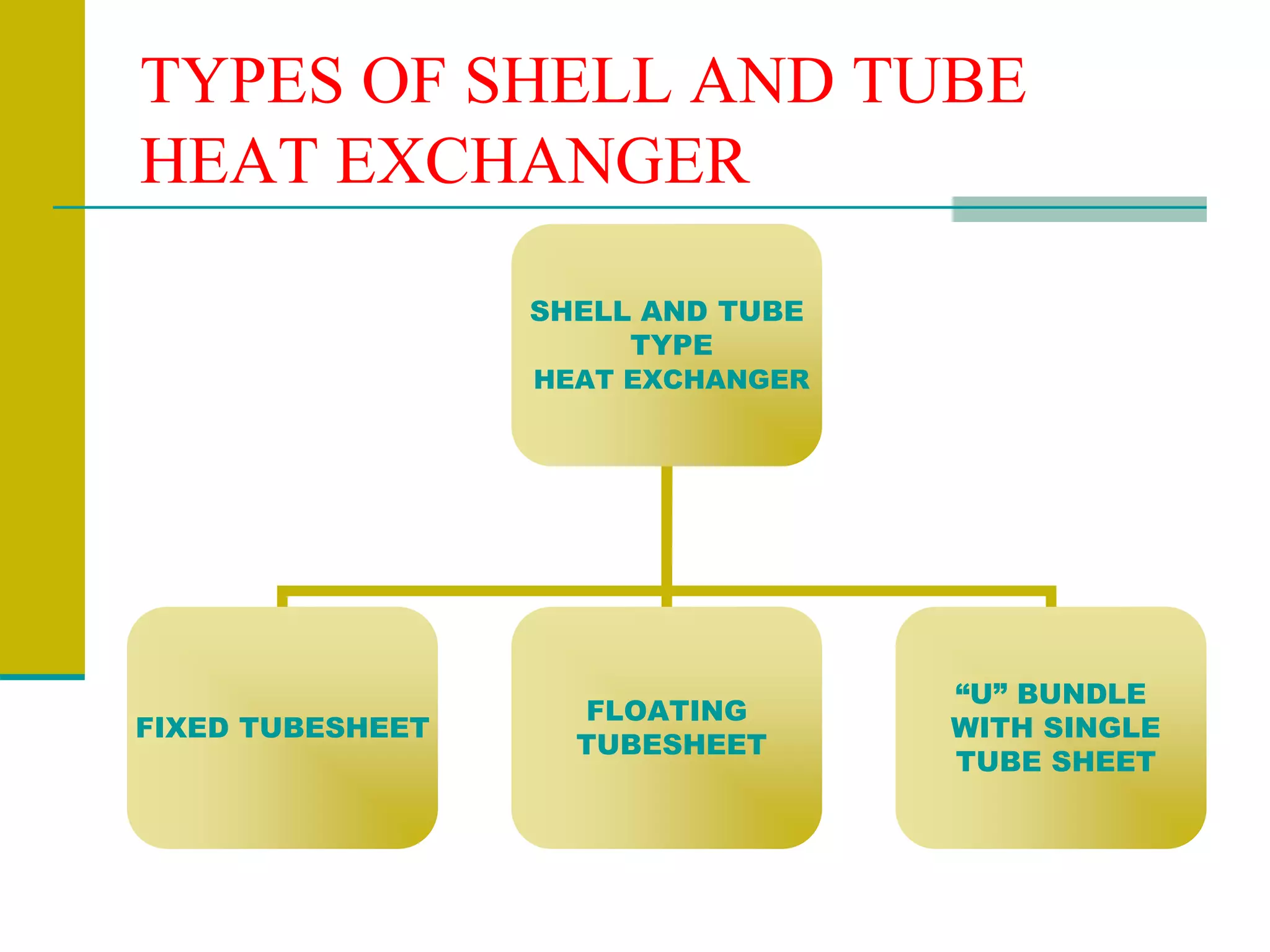
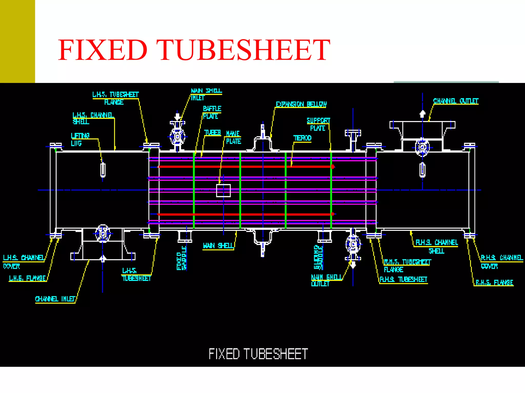
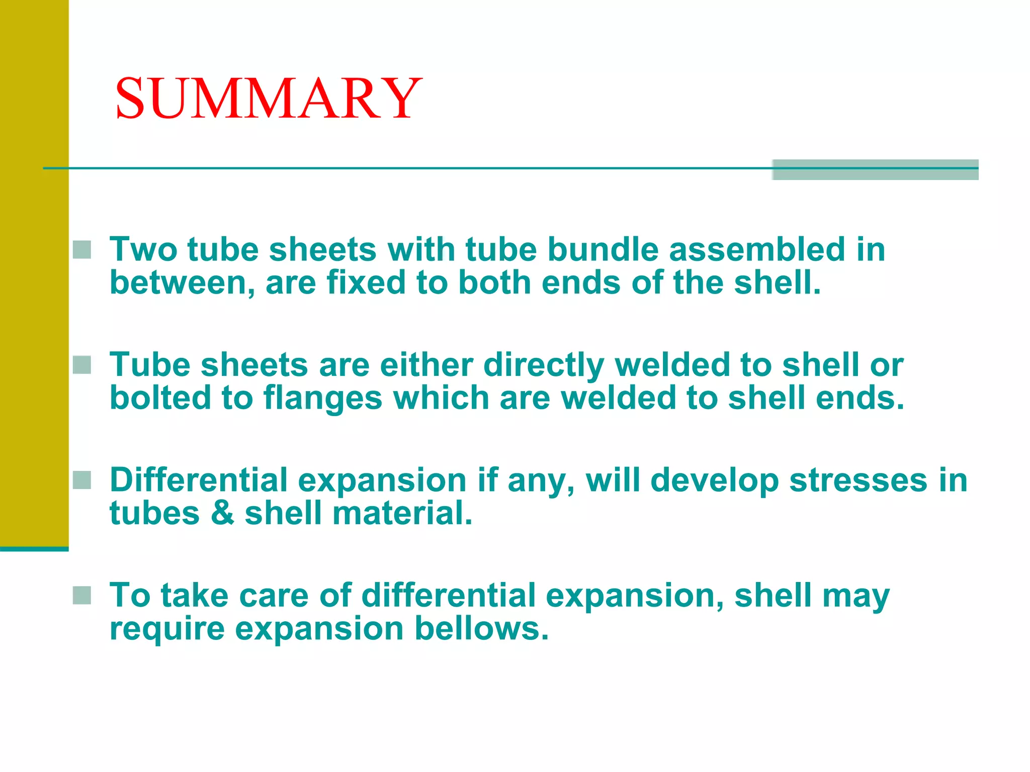
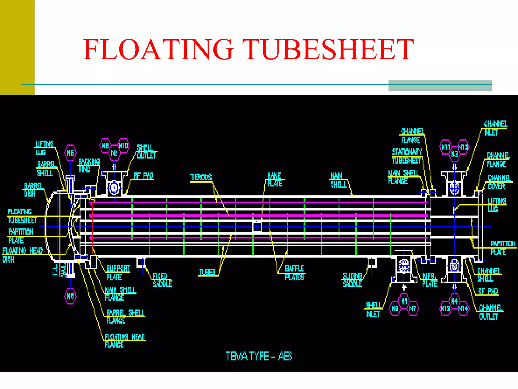
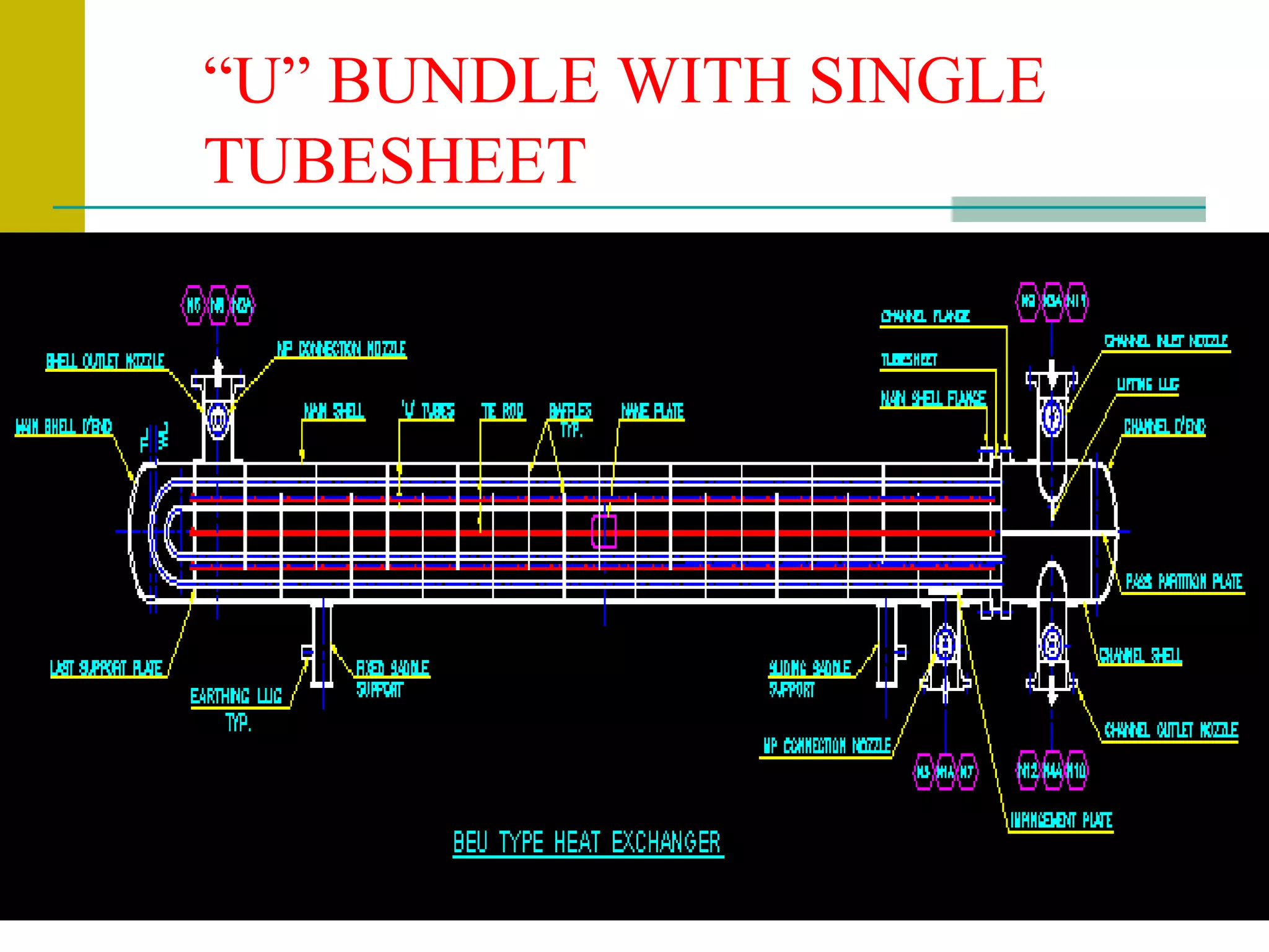
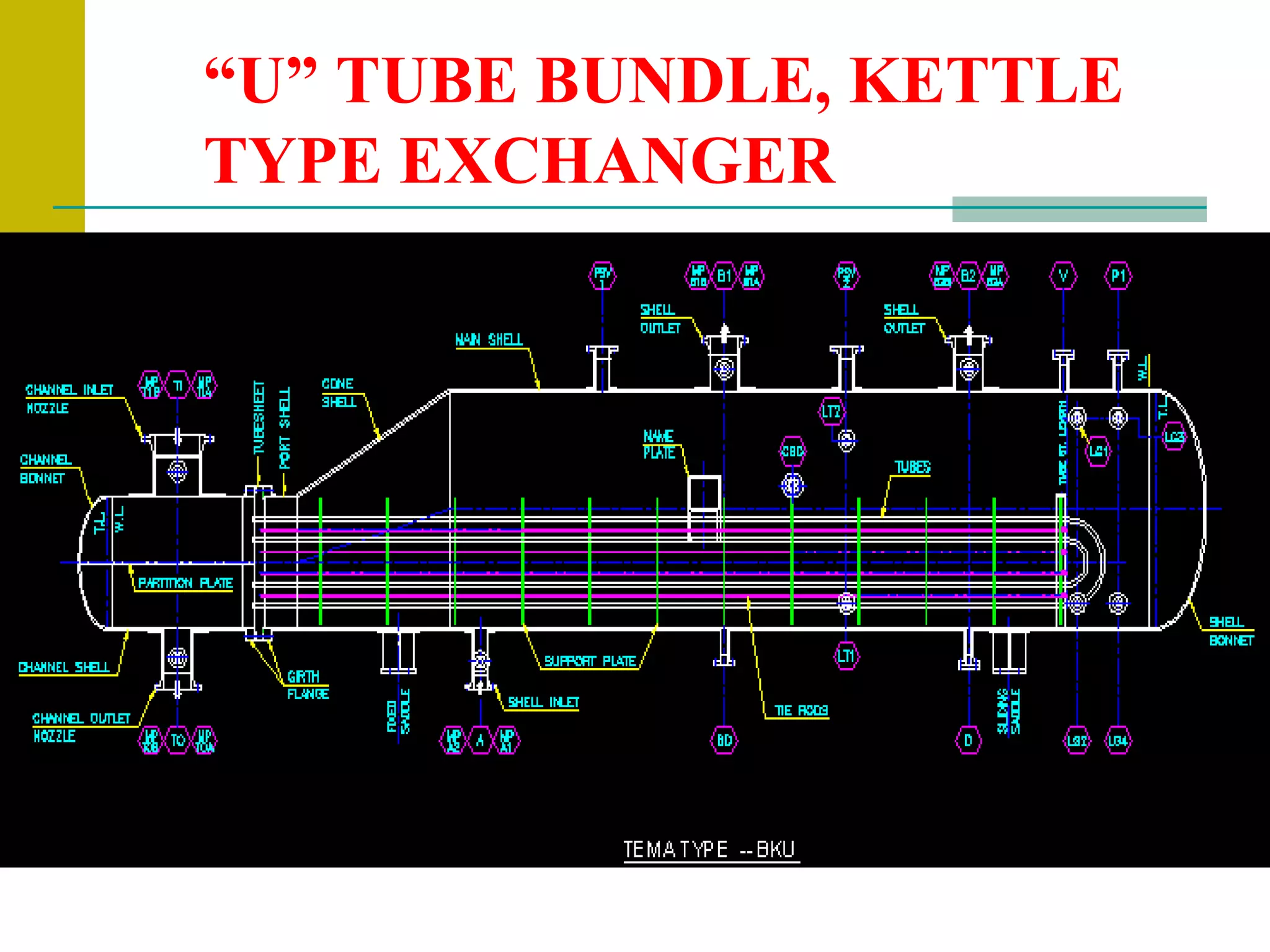
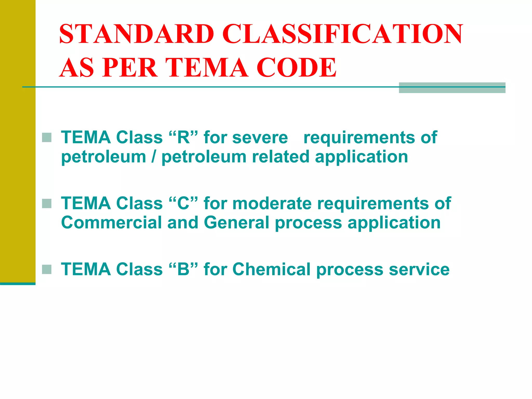
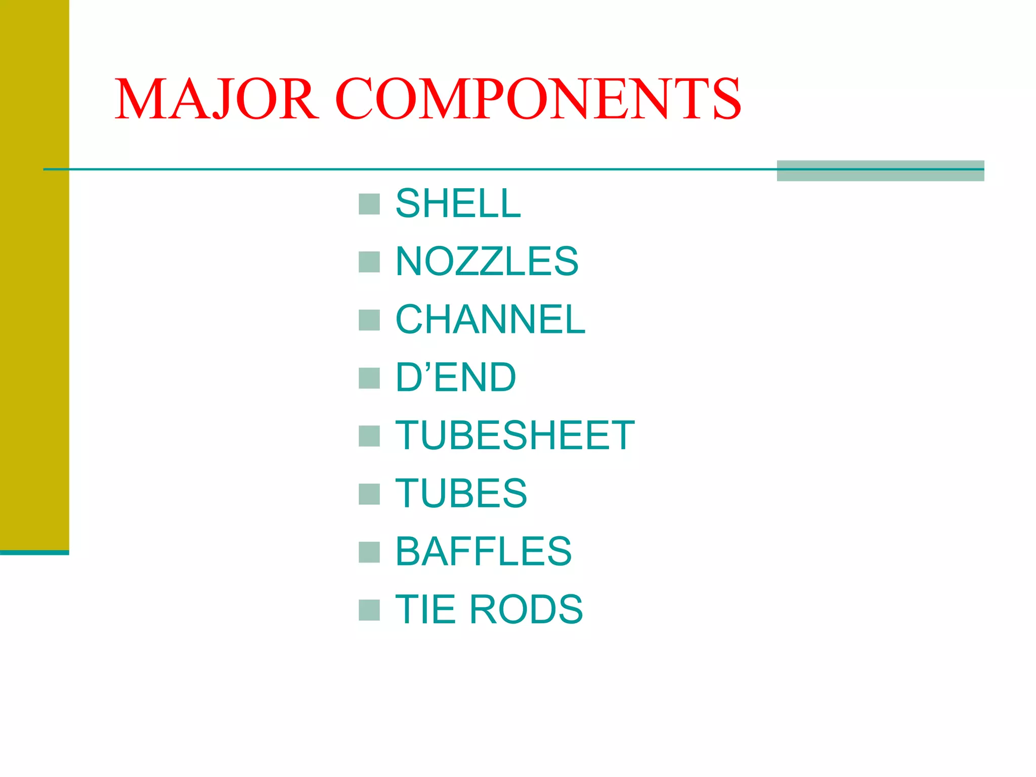
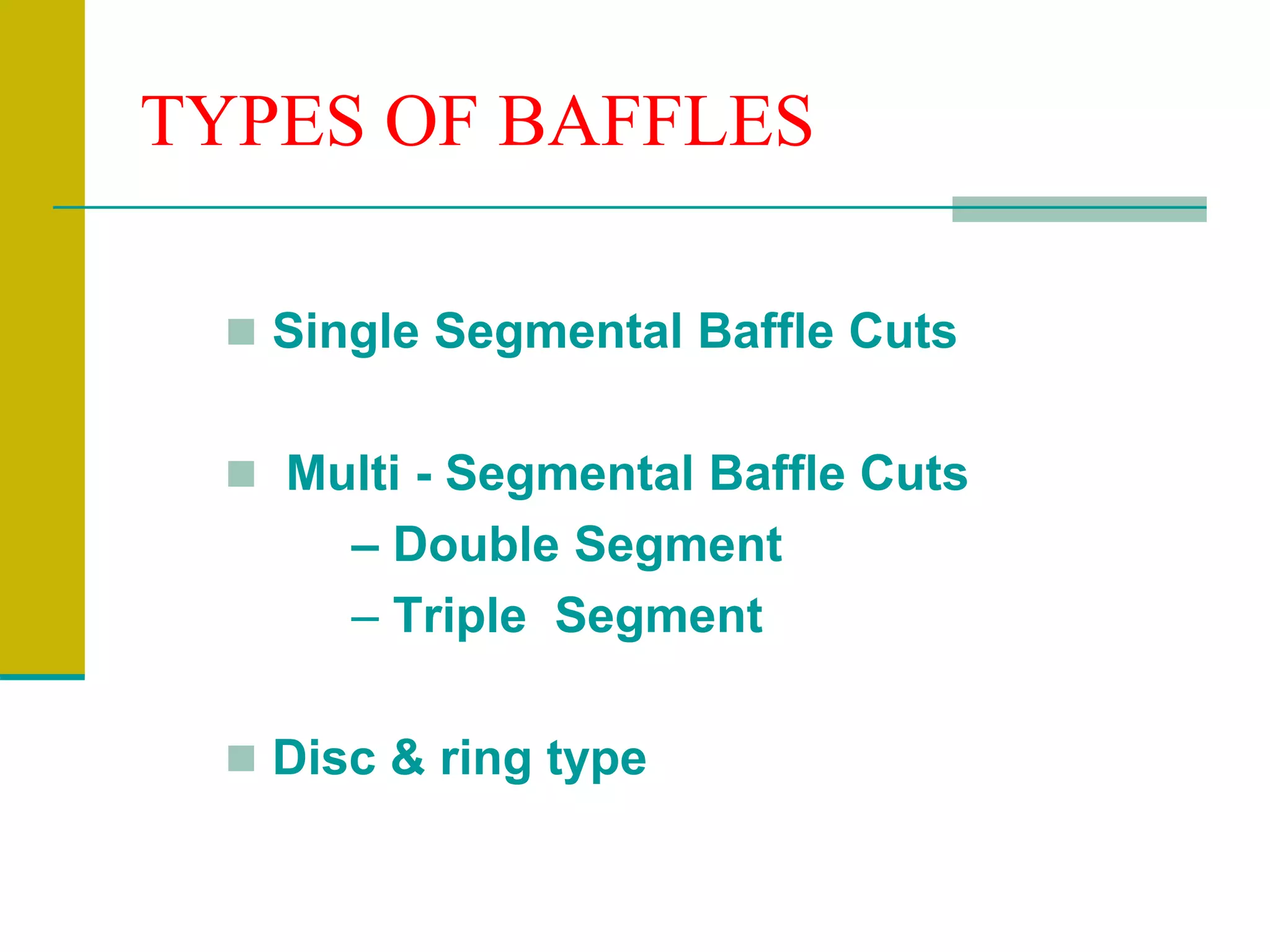
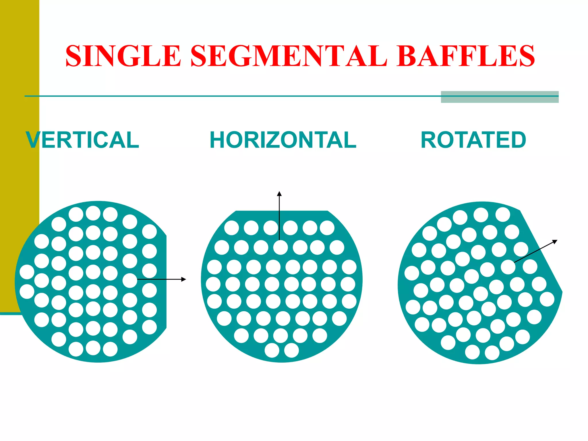
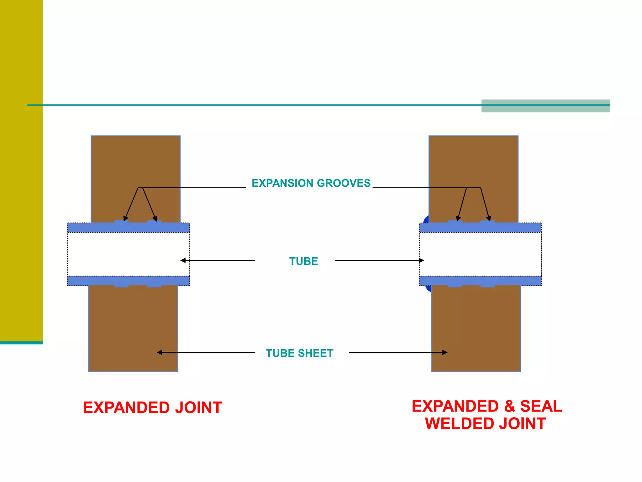
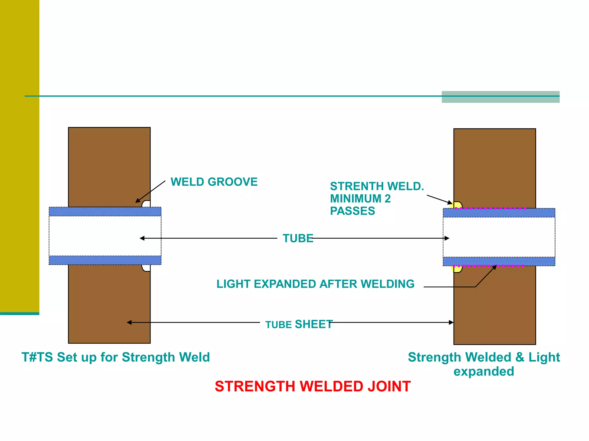
DEFINITION - HEAT EXCHANGER
 Heat exchanger is a device built for efficient heat
transfer from one fluid to another, where the fluids
are separated by a solid wall, so that they never mix.
OR
 Heat exchanger is defined as a device used to
transfer heat from a fluids on one side of a barrier to
another fluid, flowing on the other side of the barrier.
TYPES OF SHELL AND TUBE
HEAT EXCHANGER
SHELL AND TUBE
TYPE
HEAT EXCHANGER
FIXED TUBESHEET
FLOATING
TUBESHEET
“U” BUNDLE
WITH SINGLE
TUBE SHEET
FIXED TUBESHEET
SUMMARY
 Two tube sheets with tube bundle assembled in
between, are fixed to both ends of the shell.
 Tube sheets are either directly welded to shell or
bolted to flanges which are welded to shell ends.
 Differential expansion if any, will develop stresses in
tubes & shell material.
 To take care of differential expansion, shell may
require expansion bellows.
FLOATING TUBESHEET
SUMMARY
 One tubesheet is fixed to one end of the shell.
 Other tubesheet is floating within the shell with
a floating head cover.
 This facilitates tube & shell to expand independently
without inducing any stresses due to differential expansion.
 No expansion bellow is required on the shell to take
care of differential expansion.
“U” BUNDLE WITH SINGLE
TUBESHEET
“U” TUBE BUNDLE, KETTLE
TYPE EXCHANGER
SUMMARY
 “U” bent tube bundle assembled on one tubesheet.
 Assembled tube bundle is inserted into the shell.
 Tube sheet is bolted to shell flange.
 “U” tubes can expand freely inside the shell.
 No stresses due to differential expansion.
 No expansion bellow is required on shell to take
care of differential expansion.
STANDARD CLASSIFICATION
AS PER TEMA CODE
 TEMA Class “R” for severe requirements of
petroleum / petroleum related application
 TEMA Class “C” for moderate requirements of
Commercial and General process application
 TEMA Class “B” for Chemical process service
MAJOR COMPONENTS
 SHELL
 NOZZLES
 CHANNEL
 D’END
 TUBESHEET
 TUBES
 BAFFLES
 TIE RODS
FUNCTION OF BAFFLES
 They guide the shell side flow in back & forth
as well as up & down direction, across the
tube field, increasing the velocity & the heat
transfer coefficient.
 They support the tubes and hold them in
proper position during assembly & operation.
 Prevent vibration of the tubes caused by flow
induced eddies.
TYPES OF BAFFLES
 Single Segmental Baffle Cuts
 Multi - Segmental Baffle Cuts
– Double Segment
– Triple Segment
 Disc & ring type
SINGLE SEGMENTAL BAFFLES
VERTICAL HORIZONTAL ROTATED
MULTI - SEGMENTAL BAFFLE
DOUBLE SEGMENTAL CUTS
MULTI - SEGMENTAL BAFFLE
TRIPLE SEGMENTAL CUTS
DISC & RING TYPE BAFFLE
TUBE # TUBESHEET WELDING
 Tube # tubesheet welding is defined as
“process of joining tube to tubesheet in a heat
exchanger by welding”.
VARIOUS TYPES OF TUBE #
TUBESHEET JOINTS
 Strength Expanded – Exp. Grooves in Tube
holes
 Strength Expanded – Without Exp. Grooves in
Tube holes
 Seal Welded & Strength Expanded
(With or Without Expansion Grooves)
 Strength Welded (Groove Weld Joint) & Light
Expanded
TUBE
TUBE SHEET
EXPANSION GROOVES
EXPANDED JOINT EXPANDED & SEAL
WELDED JOINT
TUBE
TUBE SHEET
STRENGTH WELDED JOINT
Strength Welded & Light
expanded
STRENTH WELD.
MINIMUM 2
PASSES
WELD GROOVE
T#TS Set up for Strength Weld
LIGHT EXPANDED AFTER WELDING
WELDER QUALIFICATION PROCEDURE
SCOPE
 This procedure covers
the requirements for
welding & testing of
tube # tubesheet joint
qualification
Reference documents
 Article F-3 of ASME
SEC.IX(QW193,page-9).
 ASME SEC.VIII
 Customer specification
PREPARATION OF MOCK UP BLOCK
 The tubesheet block shall be prepared on
a plate/forging of similar base material
(Thickness = or > 50 mm) for qualification
of welding procedure.
 For qualification of welder the tubesheet
block shall be prepared a plate/forging of similar base
material (Thickness = or > 38 mm).
 After machining, tube holes shall be drilled as per block
shown in fig-1.The hole size, pitch & weld edges shall
be identical to tubesheet of the equipment
WELDER TRAINING &
QUALIFICATION
 At the beginning, welder shall be given practice on
mock up block to achieve acceptable bead finish
as mentioned below :
1) Control of welding arc to avoid melt through in tube
wall.
2) Proper arc manipulation
3) Staggering of restart points
4) Acceptable bead finishes without excessive
reinforcement
IMPORTANT NOTE
 For procedure qualification 10 mock up welds
are to be produced within acceptable
standards, as mentioned in ASME SEC IX,
QW-193.1.
 After adequate practice welders are allowed
to weld in a qualification block. The number of
joints in welder qualification block will be 5
nos as per ASME SEC IX, QW-193.2.
PRECAUTIONS BEFORE TUBE #
TUBESHEET WELDING
 Uniform welding should be carried out while
welding tubesheet # shell .
 Excessive bow will lead to difficulties while in
tube insertion stage.
Ovality should be maintained at minimum
level, to allow smooth baffle assembly.
OPERATIONAL SEQUENCES FOR
TUBE # TUBESHEET WELDING
 Inside touchup
 Baffle insertion
 Tube insertion
 Setup of tube # tubesheet
 Welding of joints
 Tube trimming
 Leak test
INSIDE TOUCHUP
 Inside touchup of entire shell is to be done to
avoid any restrictions during baffle insertion.
 All inside seam should be checked for
minimum reinforcement.
BAFFLE INSERTION
 While drilling the baffles, the drill bit usually
gets deflected from the centre line of the
hole throughout entire stack.
 Hence, it is advisable to install the baffles
in the direction of drilling with respect to
the tubing direction.
 Baffles are inserted into the shell with the
help of fixture.
FIXTURE FOR BAFFLE INSERTION
TUBE INSERTION
 Cleaning of tube & tube sheet is the most
primary requirement before tube insertion.
Utmost care is to be given for the cleaning
process according to the standard practices.
 Tube insertion is done with the help of pilots
which provides ease in tube insertion.
STANDARD L&T PRACTICES
 The tube holes and out side surface of tube
shall be cleaned thoroughly to remove any
oil, grease, rust, dust from surfaces.
 Tube ends should be cleaned minimum upto
200 mm of length at both ends by wire
wheeling.
SETUP OF TUBE # TUBESHEET
 Setup is to be done in accordance to the
projection mentioned in the drawing.
 Projection rings are utilized to ensure the
projection of tubes with respect to tube sheet.
PREPARATORY ARRANGEMENT
BEFORE WELDING
 After insertion of tubes in tube holes, the tube ends
shall be pulled outside for cleaning of tube OD. The
corresponding hole ID on opposite end shall be
cleaned (35mm, minimum). In a row, one tube shall
be pulled forward and adjoining tube shall be
pushed backward for cleaning of tube OD and hole
ID alternatively.
 Availability of high purity argon cylinder duly cleared
by welding engg. For purity check, bead-on-plate
deposit shall be carried out. After grinding the bead
to remove the half thickness, PT check shall be
performed. Each tested and cleared cylinder shall
bear signature of welding engineer.
 Thoriated Tungsten (3.0 dia.)
 High frequency unit in welding m/c is working.
 Pre and post flow of shielding gas is properly
adjusted.
 Welders are qualified to weld that particular joint and
cleared RT of joint on mock -up piece before start of
welding.
 Gas cup with gas lenses.
 Leakage of shielding gas in connections
 Water cooling system and water circulation is in
order.
 Joint shall be cleaned with acetone just before start
of tack welding
PRECAUTIONS WHILE WELDING
 Follow the welding parameters as specified in WPS.
 Welding to be performed with shortest possible arc.
 Only vertical up progression is to the used.
 Projection of tungsten electrode from gas cup shall
be kept max 6.0 mm.
 Tungsten inclusion to the avoided. In case of any
doubt the point shall the dressed before proceeding
for further welding.
 Arc initiation shall be using high frequency limit.
 Restart point in a pass shall be kept at least 4mm
before the crater point of the bead. The restart of
successive passes shall be staggered w.r.t previous
passes.
 During PT after root pass it shall be ensured that
the penetrant (dye) is not entering the un-welded
joints. If the dye has entered the in welded joints,
the joint shall be cleaned thoroughly by pulling the
tubes forward and backward.
 Weld shape & size shall be controlled to meet the
requirement of visual inspection. For weld size
correct fillet gauge shall be used.
 Only one welder shall the allowed to complete a
joint. Mix up in a joint shall be avoided.
 Welding record of each T#TS joints shall be
maintained with data and welder stamp.
 The argon cylinder shall be replaced when there is
positive pressure. ( 10 kg per sq.cm)
 Filler wire shall be cleaned with emery paper
followed by acetone cleaning. After cleaning, it shall
be handled using cleaned cotton hand glove
 While using inconel filler wire, the arc shall be kept
on CS tubes to avoid excessive melting of SS
cladding.
 Joints shall be thoroughly cleaned after PT before
depositing next passes.
 Oxidized ends of filler wire shall be cut before
reusing it.
WELDING DEFECTS
TUBE TRIMMING
 Tube trimming is required to be done after
welding root pass of all tubes in one
tubesheet.
 It is done to remove excessive tube length by
machining on job.
 Supervisor should observe that minimum
tube length trimming ( < 10mm ) is required.
LEAK TEST
 Air and soap solution leak test.
 Helium leak test.
 Kerosene leak test.
 Hot oil test.
 Halogen leak test.
USEFUL CALCULATIONS
 Welder output.
 Counterweight calculation.
 Shell trimming.
WELDER OUTPUT
 Calculate welder output for a job with 10000 nos of tube with
20mm dia per shift?
 Assume that efficiency of average welder for tube # tubesheet
welding is 25mtr/12hrs.
 Circumference of tube = 2*pie*r
= 2*3.14159*10
= 62.83mm
= 63mm approx.
 Welder output/shift = Average efficiency/circumference
= 25*1000 / 63
= 397 passes (approx).
 No of passes/tube = 2 passes / tube
 Total nos of tube which could be welded/shift = 397/2
= 199 nos (approx)
COUNTER WEIGHT CLACULATION
 Counter weight = x
 X * RHS span = Weight of baffle * LHS span
 X * 5 = 10*5
 Hence, counterweight X = 10 ton
SHELL TRIMMING
Shell trimming for A-type weld configuration.
 X = L-2P-T1-T2-B1-B2+S
SHELL TRIMMING
Shell trimming for B-type weld configuration
 X = L-2P-T1-T2-B1-B2-2H-2R+S
ABBREVATIONS
 X = Distance from the edge of tubesheet to
shell edge (actual).
 T1 = Thickness of tierod tubesheet (actual).
 T2 = Thickness of second tubesheet (actual).
 P = Required tube projection
 L = Length of tubes (actual)
 H = Height of lip on second tubesheet
 R = Root gap between tubesheet & shell
 B1 = Bulge on tie rod tubesheet after welding
(actual)
 B2 = Expected bulge on second tubesheet
 S = Shrinkage of tubesheet
Tube-to-Tube-Sheet.ppt

Tube-to-Tube-Sheet.ppt

  • 3.
    DEFINITION - HEATEXCHANGER  Heat exchanger is a device built for efficient heat transfer from one fluid to another, where the fluids are separated by a solid wall, so that they never mix. OR  Heat exchanger is defined as a device used to transfer heat from a fluids on one side of a barrier to another fluid, flowing on the other side of the barrier.
  • 4.
    TYPES OF SHELLAND TUBE HEAT EXCHANGER SHELL AND TUBE TYPE HEAT EXCHANGER FIXED TUBESHEET FLOATING TUBESHEET “U” BUNDLE WITH SINGLE TUBE SHEET
  • 5.
  • 6.
    SUMMARY  Two tubesheets with tube bundle assembled in between, are fixed to both ends of the shell.  Tube sheets are either directly welded to shell or bolted to flanges which are welded to shell ends.  Differential expansion if any, will develop stresses in tubes & shell material.  To take care of differential expansion, shell may require expansion bellows.
  • 7.
  • 8.
    SUMMARY  One tubesheetis fixed to one end of the shell.  Other tubesheet is floating within the shell with a floating head cover.  This facilitates tube & shell to expand independently without inducing any stresses due to differential expansion.  No expansion bellow is required on the shell to take care of differential expansion.
  • 9.
    “U” BUNDLE WITHSINGLE TUBESHEET
  • 10.
    “U” TUBE BUNDLE,KETTLE TYPE EXCHANGER
  • 11.
    SUMMARY  “U” benttube bundle assembled on one tubesheet.  Assembled tube bundle is inserted into the shell.  Tube sheet is bolted to shell flange.  “U” tubes can expand freely inside the shell.  No stresses due to differential expansion.  No expansion bellow is required on shell to take care of differential expansion.
  • 12.
    STANDARD CLASSIFICATION AS PERTEMA CODE  TEMA Class “R” for severe requirements of petroleum / petroleum related application  TEMA Class “C” for moderate requirements of Commercial and General process application  TEMA Class “B” for Chemical process service
  • 13.
    MAJOR COMPONENTS  SHELL NOZZLES  CHANNEL  D’END  TUBESHEET  TUBES  BAFFLES  TIE RODS
  • 14.
    FUNCTION OF BAFFLES They guide the shell side flow in back & forth as well as up & down direction, across the tube field, increasing the velocity & the heat transfer coefficient.  They support the tubes and hold them in proper position during assembly & operation.  Prevent vibration of the tubes caused by flow induced eddies.
  • 15.
    TYPES OF BAFFLES Single Segmental Baffle Cuts  Multi - Segmental Baffle Cuts – Double Segment – Triple Segment  Disc & ring type
  • 16.
  • 17.
    MULTI - SEGMENTALBAFFLE DOUBLE SEGMENTAL CUTS
  • 18.
    MULTI - SEGMENTALBAFFLE TRIPLE SEGMENTAL CUTS
  • 19.
    DISC & RINGTYPE BAFFLE
  • 21.
    TUBE # TUBESHEETWELDING  Tube # tubesheet welding is defined as “process of joining tube to tubesheet in a heat exchanger by welding”.
  • 22.
    VARIOUS TYPES OFTUBE # TUBESHEET JOINTS  Strength Expanded – Exp. Grooves in Tube holes  Strength Expanded – Without Exp. Grooves in Tube holes  Seal Welded & Strength Expanded (With or Without Expansion Grooves)  Strength Welded (Groove Weld Joint) & Light Expanded
  • 23.
    TUBE TUBE SHEET EXPANSION GROOVES EXPANDEDJOINT EXPANDED & SEAL WELDED JOINT
  • 24.
    TUBE TUBE SHEET STRENGTH WELDEDJOINT Strength Welded & Light expanded STRENTH WELD. MINIMUM 2 PASSES WELD GROOVE T#TS Set up for Strength Weld LIGHT EXPANDED AFTER WELDING
  • 25.
    WELDER QUALIFICATION PROCEDURE SCOPE This procedure covers the requirements for welding & testing of tube # tubesheet joint qualification Reference documents  Article F-3 of ASME SEC.IX(QW193,page-9).  ASME SEC.VIII  Customer specification
  • 26.
    PREPARATION OF MOCKUP BLOCK  The tubesheet block shall be prepared on a plate/forging of similar base material (Thickness = or > 50 mm) for qualification of welding procedure.  For qualification of welder the tubesheet block shall be prepared a plate/forging of similar base material (Thickness = or > 38 mm).  After machining, tube holes shall be drilled as per block shown in fig-1.The hole size, pitch & weld edges shall be identical to tubesheet of the equipment
  • 28.
    WELDER TRAINING & QUALIFICATION At the beginning, welder shall be given practice on mock up block to achieve acceptable bead finish as mentioned below : 1) Control of welding arc to avoid melt through in tube wall. 2) Proper arc manipulation 3) Staggering of restart points 4) Acceptable bead finishes without excessive reinforcement
  • 29.
    IMPORTANT NOTE  Forprocedure qualification 10 mock up welds are to be produced within acceptable standards, as mentioned in ASME SEC IX, QW-193.1.  After adequate practice welders are allowed to weld in a qualification block. The number of joints in welder qualification block will be 5 nos as per ASME SEC IX, QW-193.2.
  • 30.
    PRECAUTIONS BEFORE TUBE# TUBESHEET WELDING  Uniform welding should be carried out while welding tubesheet # shell .  Excessive bow will lead to difficulties while in tube insertion stage.
  • 31.
    Ovality should bemaintained at minimum level, to allow smooth baffle assembly.
  • 32.
    OPERATIONAL SEQUENCES FOR TUBE# TUBESHEET WELDING  Inside touchup  Baffle insertion  Tube insertion  Setup of tube # tubesheet  Welding of joints  Tube trimming  Leak test
  • 33.
    INSIDE TOUCHUP  Insidetouchup of entire shell is to be done to avoid any restrictions during baffle insertion.  All inside seam should be checked for minimum reinforcement.
  • 34.
    BAFFLE INSERTION  Whiledrilling the baffles, the drill bit usually gets deflected from the centre line of the hole throughout entire stack.  Hence, it is advisable to install the baffles in the direction of drilling with respect to the tubing direction.  Baffles are inserted into the shell with the help of fixture.
  • 37.
  • 38.
    TUBE INSERTION  Cleaningof tube & tube sheet is the most primary requirement before tube insertion. Utmost care is to be given for the cleaning process according to the standard practices.  Tube insertion is done with the help of pilots which provides ease in tube insertion.
  • 39.
    STANDARD L&T PRACTICES The tube holes and out side surface of tube shall be cleaned thoroughly to remove any oil, grease, rust, dust from surfaces.  Tube ends should be cleaned minimum upto 200 mm of length at both ends by wire wheeling.
  • 41.
    SETUP OF TUBE# TUBESHEET  Setup is to be done in accordance to the projection mentioned in the drawing.  Projection rings are utilized to ensure the projection of tubes with respect to tube sheet.
  • 43.
    PREPARATORY ARRANGEMENT BEFORE WELDING After insertion of tubes in tube holes, the tube ends shall be pulled outside for cleaning of tube OD. The corresponding hole ID on opposite end shall be cleaned (35mm, minimum). In a row, one tube shall be pulled forward and adjoining tube shall be pushed backward for cleaning of tube OD and hole ID alternatively.  Availability of high purity argon cylinder duly cleared by welding engg. For purity check, bead-on-plate deposit shall be carried out. After grinding the bead to remove the half thickness, PT check shall be performed. Each tested and cleared cylinder shall bear signature of welding engineer.
  • 44.
     Thoriated Tungsten(3.0 dia.)  High frequency unit in welding m/c is working.  Pre and post flow of shielding gas is properly adjusted.  Welders are qualified to weld that particular joint and cleared RT of joint on mock -up piece before start of welding.  Gas cup with gas lenses.  Leakage of shielding gas in connections  Water cooling system and water circulation is in order.  Joint shall be cleaned with acetone just before start of tack welding
  • 46.
    PRECAUTIONS WHILE WELDING Follow the welding parameters as specified in WPS.  Welding to be performed with shortest possible arc.  Only vertical up progression is to the used.  Projection of tungsten electrode from gas cup shall be kept max 6.0 mm.  Tungsten inclusion to the avoided. In case of any doubt the point shall the dressed before proceeding for further welding.  Arc initiation shall be using high frequency limit.  Restart point in a pass shall be kept at least 4mm before the crater point of the bead. The restart of successive passes shall be staggered w.r.t previous passes.
  • 47.
     During PTafter root pass it shall be ensured that the penetrant (dye) is not entering the un-welded joints. If the dye has entered the in welded joints, the joint shall be cleaned thoroughly by pulling the tubes forward and backward.  Weld shape & size shall be controlled to meet the requirement of visual inspection. For weld size correct fillet gauge shall be used.  Only one welder shall the allowed to complete a joint. Mix up in a joint shall be avoided.  Welding record of each T#TS joints shall be maintained with data and welder stamp.  The argon cylinder shall be replaced when there is positive pressure. ( 10 kg per sq.cm)
  • 48.
     Filler wireshall be cleaned with emery paper followed by acetone cleaning. After cleaning, it shall be handled using cleaned cotton hand glove  While using inconel filler wire, the arc shall be kept on CS tubes to avoid excessive melting of SS cladding.  Joints shall be thoroughly cleaned after PT before depositing next passes.  Oxidized ends of filler wire shall be cut before reusing it.
  • 49.
  • 51.
    TUBE TRIMMING  Tubetrimming is required to be done after welding root pass of all tubes in one tubesheet.  It is done to remove excessive tube length by machining on job.  Supervisor should observe that minimum tube length trimming ( < 10mm ) is required.
  • 52.
    LEAK TEST  Airand soap solution leak test.  Helium leak test.  Kerosene leak test.  Hot oil test.  Halogen leak test.
  • 53.
    USEFUL CALCULATIONS  Welderoutput.  Counterweight calculation.  Shell trimming.
  • 54.
    WELDER OUTPUT  Calculatewelder output for a job with 10000 nos of tube with 20mm dia per shift?  Assume that efficiency of average welder for tube # tubesheet welding is 25mtr/12hrs.  Circumference of tube = 2*pie*r = 2*3.14159*10 = 62.83mm = 63mm approx.  Welder output/shift = Average efficiency/circumference = 25*1000 / 63 = 397 passes (approx).  No of passes/tube = 2 passes / tube  Total nos of tube which could be welded/shift = 397/2 = 199 nos (approx)
  • 55.
    COUNTER WEIGHT CLACULATION Counter weight = x  X * RHS span = Weight of baffle * LHS span  X * 5 = 10*5  Hence, counterweight X = 10 ton
  • 56.
    SHELL TRIMMING Shell trimmingfor A-type weld configuration.  X = L-2P-T1-T2-B1-B2+S
  • 57.
    SHELL TRIMMING Shell trimmingfor B-type weld configuration  X = L-2P-T1-T2-B1-B2-2H-2R+S
  • 58.
    ABBREVATIONS  X =Distance from the edge of tubesheet to shell edge (actual).  T1 = Thickness of tierod tubesheet (actual).  T2 = Thickness of second tubesheet (actual).  P = Required tube projection  L = Length of tubes (actual)  H = Height of lip on second tubesheet  R = Root gap between tubesheet & shell  B1 = Bulge on tie rod tubesheet after welding (actual)  B2 = Expected bulge on second tubesheet  S = Shrinkage of tubesheet