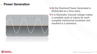
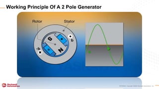
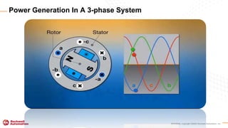
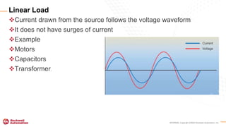
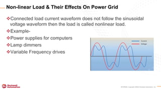
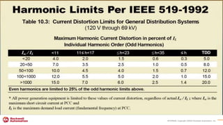
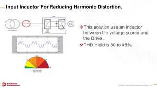
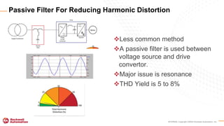
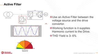
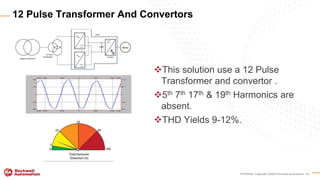
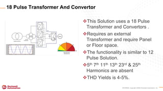
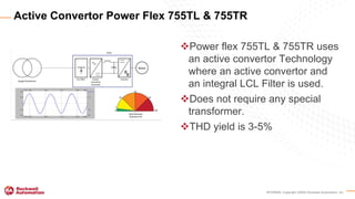
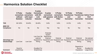
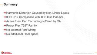
Copyright © 2013 Rockwell Automation, Inc. All Rights Reserved.
COMPANY CONFIDENTIAL - Internal Use Only
Harmonic Analysis
Chandra Shekhar Yadav • A Guide to Understanding and Successful control | 19th February 2021
Copyright ©2018 Rockwell Automation, Inc. 2
Agenda
Fundamental
of Power
Generation &
Insight to
System
Harmonics
Cause of
Harmonic
Distortion
Liner and
Non-Linear
Loads
Risks of
Harmonic
Current to
Electrical
System &
Harmonic
Standards
IEEE-519
Solutions to
Mitigate and
Meet the
standards
1 2 3 4
INTERNAL Copyright ©2020 Rockwell Automation, Inc.
FUNDAMENTALS
OF
POWER GENERATION
INTERNAL Copyright ©2020 Rockwell Automation, Inc.
All the Electrical Power Generated is
Distributed as a Sine wave.
In a Generator induced voltage makes
a complete cycle of values for each
complete mechanical revolution and
resultant is a sinewave.
Power Generation
INTERNAL Copyright ©2020 Rockwell Automation, Inc.
Working Principle Of A 2 Pole Generator
INTERNAL Copyright ©2020 Rockwell Automation, Inc.
Power Generation In A 3-phase System
INTERNAL Copyright ©2020 Rockwell Automation, Inc.
Current drawn from the source follows the voltage waveform
It does not have surges of current
Example
Motors
Capacitors
Transformer.
Linear Load
INTERNAL Copyright ©2020 Rockwell Automation, Inc.
Connected load current waveform does not follow the sinusoidal
voltage waveform then the load is called nonlinear load.
Example-
Power supplies for computers
Lamp dimmers
Variable Frequency drives
Non-linear Load & Their Effects On Power Grid
INTERNAL Copyright ©2020 Rockwell Automation, Inc.
Line losses
Equipment damage
Increased power costs
Wasted energy
Hazard Of Degraded Power
INTERNAL Copyright ©2020 Rockwell Automation, Inc.
PROBLEMS ASSOCIATED
WITH
HARMONIC DISTORTION
INTERNAL Copyright ©2020 Rockwell Automation, Inc.
Effects on Customer Sharing The Same Grid
INTERNAL Copyright ©2020 Rockwell Automation, Inc.
Water/Hose Analogy
INTERNAL Copyright ©2020 Rockwell Automation, Inc.
DEFINING
AND
QUANTIFYING INCONSISTENCIES
ON
THE POWER GRID
INTERNAL Copyright ©2020 Rockwell Automation, Inc.
A distorted current waveform
creates heat in the power delivery
equipment.
Resolving a non-liner waveform
into its sinusoidal components is
called harmonic analysis
Harmonic analysis will estimate the
heating effects due to nonlinear
current flowing through circuit
breaker and transformer
Distorted Current Waveform
INTERNAL Copyright ©2020 Rockwell Automation, Inc.
Jean Baptiste Joseph Fourier
(21st March 1786 – 16th May1830)
Mathematician
Physicist
Fourier Series
Fourier Transform
Fourier Law of Conduction.
Man Behind Idea For Resolving The Harmonics
INTERNAL Copyright ©2020 Rockwell Automation, Inc.
Fundamental sine wave
Plus
Harmonics
Equals
Harmonically Distorted Waveform.
Understanding A Harmonically Distorted Waveform
INTERNAL Copyright ©2020 Rockwell Automation, Inc.
Ratio of square root of the sum of squares of the rms value of harmonic
component to the rms value of the fundamental component is defined as total
harmonic distortion (THD).
If the waveform under discussion is current, then the THD definition is called
current harmonic distortion . If the waveform under discussion is voltage, then
the THD definition is called Voltage Harmonic Distortion.
Definition Of THD
INTERNAL Copyright ©2020 Rockwell Automation, Inc.
THD=(P Total - P1)/P1
1 2 3 4 5 6 7 8 9 10 11 12 13 14 15 16 17 18 19 20 21 22 23 24 25
Harmonics
Expressed as percentage of the fundamental
Odd Harmonics that Contribute to THD –In a Three Phase power system these harmonics are considered
when performing a harmonic analysis.5th 7th 11th 13th 17th 19th 23rd 25th harmonics
Total Harmonic Distortion
INTERNAL Copyright ©2020 Rockwell Automation, Inc.
IEEE-519-1992
INTERNAL Copyright ©2020 Rockwell Automation, Inc.
Total Harmonic Distortion
Based on the Fundamental Current on a Cycle-to-Cycle Basis.
Total Demand Distortion
Moving average of THD Based on System Rated Current
Uses a Much Longer Averaging Time.
THD & TDD
INTERNAL Copyright ©2020 Rockwell Automation, Inc.
• All power generation is limited to these values of current distortion,
regardless of actual Isc/IL : where Isc is the maximum short circuit
current at PCC and
• IL is the maximum demand load current (Fundamental Frequency) at
PCC.
INTERNAL Copyright ©2020 Rockwell Automation, Inc.
Size and Impedance of Power
Source relative to Drive
Severity is low when power
source is large and drives
operating are comparatively
small.
TDD Level- 20% is Acceptable
Severity Of The Problem On Small Drive System
INTERNAL Copyright ©2020 Rockwell Automation, Inc.
Severity Increases variably if
Power source is smaller in
comparison with the Drive
operating or Drive is Larger
comparatively from the source
operating it.
TDD Level 5% are only
acceptable
Severity Of The Problem When Drive Is Large.
INTERNAL Copyright ©2020 Rockwell Automation, Inc.
Dependent on
Based on input rectifier
Size relation ship between the drive and the power source
What Kind Of Harmonics Do A VFD Create?
INTERNAL Copyright ©2020 Rockwell Automation, Inc.
HARMONIC MITIGATION
TECHNIQUES
INTERNAL Copyright ©2020 Rockwell Automation, Inc.
Drives with Conventional Diode
or SCR Convertors will Produce
Total Harmonic Distortion in
order of 80 to 120%.
This distortion may not have a
big effect at the point of common
coupling as it draws small
amount of current in case of a
small drive.
What’s Normal Harmonic Distortion In A Drive
INTERNAL Copyright ©2020 Rockwell Automation, Inc.
This solution using DC Link
inductor. It uses inductor
between convertor and DC Bus.
Smoothed out Current waveform
THD Yield is 30 to 45%.
Dc Link Inductor For Reducing Harmonic Distortion
INTERNAL Copyright ©2020 Rockwell Automation, Inc.
This solution use an inductor
between the voltage source and
the Drive .
THD Yield is 30 to 45%.
Input Inductor For Reducing Harmonic Distortion.
INTERNAL Copyright ©2020 Rockwell Automation, Inc.
Less common method
A passive filter is used between
voltage source and drive
convertor.
Major issue is resonance
THD Yield is 5 to 8%
Passive Filter For Reducing Harmonic Distortion
INTERNAL Copyright ©2020 Rockwell Automation, Inc.
Use an Active Filter between the
voltage source and the drive
convertor.
Working function is it supplies
Harmonic current to the Drive.
THD Yield is 3- 6%
Active Filter
INTERNAL Copyright ©2020 Rockwell Automation, Inc.
This solution use a 12 Pulse
Transformer and convertor .
5th 7th 17th & 19th Harmonics are
absent.
THD Yields 9-12%.
12 Pulse Transformer And Convertors
INTERNAL Copyright ©2020 Rockwell Automation, Inc.
The Harmonics Generated by a 3 Phase AC system is given by Mathematical Formula
H=Kq+1
H= The Harmonic Number
K= an Integer
q= the number of humps or rectifier per electrical cycle on the DC bus.
Mathematical Formula of Harmonics
6 pulse Drive (h) 12 pulse Drive (h) 18 pulse Drive (h)
1*6-1=5 1*12-1=11 1*18-1=17
1*6+1=7 1*12+1=13 1*18+1=19
2*6-1=11 2*12-1=23 2*18-1=35
2*6+1=13 2*12+1=25 2*18+1=37
3*6-1=17 3*12-1=35 3*18-1=53
3*6+1=19 3*12+1=37 3*18+1=55
INTERNAL Copyright ©2020 Rockwell Automation, Inc.
This Solution uses a 18 Pulse
Transformer and Convertors .
Requires an external
Transformer and require Panel
or Floor space.
The functionality is similar to 12
Pulse Solution.
5th 7th 11th 13th 23rd & 25th
Harmonics are absent
THD Yields is 4-5%.
18 Pulse Transformer And Convertor
INTERNAL Copyright ©2020 Rockwell Automation, Inc.
Power flex 755TL & 755TR uses
an active convertor Technology
where an active convertor and
an integral LCL Filter is used.
Does not require any special
transformer.
THD yield is 3-5%
Active Convertor Power Flex 755TL & 755TR
INTERNAL Copyright ©2020 Rockwell Automation, Inc.
Harmonics Solution Checklist
6 Pulse
convertors
without
Solution
6 pulse
convertors
with input
inductor
6 pulse
Convertors
with DC
Link
Inductor
6 pulse
convertors
with passive
filter
6 Pulse
convertors
with Active
Filter
12 Pulse
Transformer
and
Convertor
18 Pulse
Transformer
and
Convertor
Active Front
End
Convertor
THD 80-120% 30-45% 30-45% 5-8% 3-6% 8-12% 4-8% 3-5%
IEEE 519
Compliance No No No Yes Yes No Yes Yes
Advantage and
Disadvantage Low Cost Low Cost
Low Cost, No
external
Equipment or
Wiring
Potential
System
Resonance ,
External
Equipment and
wiring
External
Equipment and
Wiring
External
Equipment and
Wiring
External
Equipment and
Wiring
No external
Equipment or
wiring
Comment
Good for
small Drives
Excellent For
Small Drives
Depends on
Source
Impedance
Excellent for
Large Drives
INTERNAL Copyright ©2020 Rockwell Automation, Inc.
Harmonic Distortion Caused by Non-Linear Loads
IEEE 519 Compliance with THD less than 5%.
Active Front End Technology offered by RA
Power Flex 755T Family
No external Part/Wiring
No additional Floor space
Summary
INTERNAL Copyright ©2020 Rockwell Automation, Inc.
Questions ?
INTERNAL Copyright ©2020 Rockwell Automation, Inc.
www.rockwellautomation.com
Thank you

Harmonics Analysis

  • 1.
    Copyright © 2013Rockwell Automation, Inc. All Rights Reserved. COMPANY CONFIDENTIAL - Internal Use Only Harmonic Analysis Chandra Shekhar Yadav • A Guide to Understanding and Successful control | 19th February 2021
  • 2.
    Copyright ©2018 RockwellAutomation, Inc. 2 Agenda Fundamental of Power Generation & Insight to System Harmonics Cause of Harmonic Distortion Liner and Non-Linear Loads Risks of Harmonic Current to Electrical System & Harmonic Standards IEEE-519 Solutions to Mitigate and Meet the standards 1 2 3 4
  • 3.
    INTERNAL Copyright ©2020Rockwell Automation, Inc. FUNDAMENTALS OF POWER GENERATION
  • 4.
    INTERNAL Copyright ©2020Rockwell Automation, Inc. All the Electrical Power Generated is Distributed as a Sine wave. In a Generator induced voltage makes a complete cycle of values for each complete mechanical revolution and resultant is a sinewave. Power Generation
  • 5.
    INTERNAL Copyright ©2020Rockwell Automation, Inc. Working Principle Of A 2 Pole Generator
  • 6.
    INTERNAL Copyright ©2020Rockwell Automation, Inc. Power Generation In A 3-phase System
  • 7.
    INTERNAL Copyright ©2020Rockwell Automation, Inc. Current drawn from the source follows the voltage waveform It does not have surges of current Example Motors Capacitors Transformer. Linear Load
  • 8.
    INTERNAL Copyright ©2020Rockwell Automation, Inc. Connected load current waveform does not follow the sinusoidal voltage waveform then the load is called nonlinear load. Example- Power supplies for computers Lamp dimmers Variable Frequency drives Non-linear Load & Their Effects On Power Grid
  • 9.
    INTERNAL Copyright ©2020Rockwell Automation, Inc. Line losses Equipment damage Increased power costs Wasted energy Hazard Of Degraded Power
  • 10.
    INTERNAL Copyright ©2020Rockwell Automation, Inc. PROBLEMS ASSOCIATED WITH HARMONIC DISTORTION
  • 11.
    INTERNAL Copyright ©2020Rockwell Automation, Inc. Effects on Customer Sharing The Same Grid
  • 12.
    INTERNAL Copyright ©2020Rockwell Automation, Inc. Water/Hose Analogy
  • 13.
    INTERNAL Copyright ©2020Rockwell Automation, Inc. DEFINING AND QUANTIFYING INCONSISTENCIES ON THE POWER GRID
  • 14.
    INTERNAL Copyright ©2020Rockwell Automation, Inc. A distorted current waveform creates heat in the power delivery equipment. Resolving a non-liner waveform into its sinusoidal components is called harmonic analysis Harmonic analysis will estimate the heating effects due to nonlinear current flowing through circuit breaker and transformer Distorted Current Waveform
  • 15.
    INTERNAL Copyright ©2020Rockwell Automation, Inc. Jean Baptiste Joseph Fourier (21st March 1786 – 16th May1830) Mathematician Physicist Fourier Series Fourier Transform Fourier Law of Conduction. Man Behind Idea For Resolving The Harmonics
  • 16.
    INTERNAL Copyright ©2020Rockwell Automation, Inc. Fundamental sine wave Plus Harmonics Equals Harmonically Distorted Waveform. Understanding A Harmonically Distorted Waveform
  • 17.
    INTERNAL Copyright ©2020Rockwell Automation, Inc. Ratio of square root of the sum of squares of the rms value of harmonic component to the rms value of the fundamental component is defined as total harmonic distortion (THD). If the waveform under discussion is current, then the THD definition is called current harmonic distortion . If the waveform under discussion is voltage, then the THD definition is called Voltage Harmonic Distortion. Definition Of THD
  • 18.
    INTERNAL Copyright ©2020Rockwell Automation, Inc. THD=(P Total - P1)/P1 1 2 3 4 5 6 7 8 9 10 11 12 13 14 15 16 17 18 19 20 21 22 23 24 25 Harmonics Expressed as percentage of the fundamental Odd Harmonics that Contribute to THD –In a Three Phase power system these harmonics are considered when performing a harmonic analysis.5th 7th 11th 13th 17th 19th 23rd 25th harmonics Total Harmonic Distortion
  • 19.
    INTERNAL Copyright ©2020Rockwell Automation, Inc. IEEE-519-1992
  • 20.
    INTERNAL Copyright ©2020Rockwell Automation, Inc.
  • 21.
    INTERNAL Copyright ©2020Rockwell Automation, Inc. Total Harmonic Distortion Based on the Fundamental Current on a Cycle-to-Cycle Basis. Total Demand Distortion Moving average of THD Based on System Rated Current Uses a Much Longer Averaging Time. THD & TDD
  • 22.
    INTERNAL Copyright ©2020Rockwell Automation, Inc. • All power generation is limited to these values of current distortion, regardless of actual Isc/IL : where Isc is the maximum short circuit current at PCC and • IL is the maximum demand load current (Fundamental Frequency) at PCC.
  • 23.
    INTERNAL Copyright ©2020Rockwell Automation, Inc. Size and Impedance of Power Source relative to Drive Severity is low when power source is large and drives operating are comparatively small. TDD Level- 20% is Acceptable Severity Of The Problem On Small Drive System
  • 24.
    INTERNAL Copyright ©2020Rockwell Automation, Inc. Severity Increases variably if Power source is smaller in comparison with the Drive operating or Drive is Larger comparatively from the source operating it. TDD Level 5% are only acceptable Severity Of The Problem When Drive Is Large.
  • 25.
    INTERNAL Copyright ©2020Rockwell Automation, Inc. Dependent on Based on input rectifier Size relation ship between the drive and the power source What Kind Of Harmonics Do A VFD Create?
  • 26.
    INTERNAL Copyright ©2020Rockwell Automation, Inc. HARMONIC MITIGATION TECHNIQUES
  • 27.
    INTERNAL Copyright ©2020Rockwell Automation, Inc. Drives with Conventional Diode or SCR Convertors will Produce Total Harmonic Distortion in order of 80 to 120%. This distortion may not have a big effect at the point of common coupling as it draws small amount of current in case of a small drive. What’s Normal Harmonic Distortion In A Drive
  • 28.
    INTERNAL Copyright ©2020Rockwell Automation, Inc. This solution using DC Link inductor. It uses inductor between convertor and DC Bus. Smoothed out Current waveform THD Yield is 30 to 45%. Dc Link Inductor For Reducing Harmonic Distortion
  • 29.
    INTERNAL Copyright ©2020Rockwell Automation, Inc. This solution use an inductor between the voltage source and the Drive . THD Yield is 30 to 45%. Input Inductor For Reducing Harmonic Distortion.
  • 30.
    INTERNAL Copyright ©2020Rockwell Automation, Inc. Less common method A passive filter is used between voltage source and drive convertor. Major issue is resonance THD Yield is 5 to 8% Passive Filter For Reducing Harmonic Distortion
  • 31.
    INTERNAL Copyright ©2020Rockwell Automation, Inc. Use an Active Filter between the voltage source and the drive convertor. Working function is it supplies Harmonic current to the Drive. THD Yield is 3- 6% Active Filter
  • 32.
    INTERNAL Copyright ©2020Rockwell Automation, Inc. This solution use a 12 Pulse Transformer and convertor . 5th 7th 17th & 19th Harmonics are absent. THD Yields 9-12%. 12 Pulse Transformer And Convertors
  • 33.
    INTERNAL Copyright ©2020Rockwell Automation, Inc. The Harmonics Generated by a 3 Phase AC system is given by Mathematical Formula H=Kq+1 H= The Harmonic Number K= an Integer q= the number of humps or rectifier per electrical cycle on the DC bus. Mathematical Formula of Harmonics 6 pulse Drive (h) 12 pulse Drive (h) 18 pulse Drive (h) 1*6-1=5 1*12-1=11 1*18-1=17 1*6+1=7 1*12+1=13 1*18+1=19 2*6-1=11 2*12-1=23 2*18-1=35 2*6+1=13 2*12+1=25 2*18+1=37 3*6-1=17 3*12-1=35 3*18-1=53 3*6+1=19 3*12+1=37 3*18+1=55
  • 34.
    INTERNAL Copyright ©2020Rockwell Automation, Inc. This Solution uses a 18 Pulse Transformer and Convertors . Requires an external Transformer and require Panel or Floor space. The functionality is similar to 12 Pulse Solution. 5th 7th 11th 13th 23rd & 25th Harmonics are absent THD Yields is 4-5%. 18 Pulse Transformer And Convertor
  • 35.
    INTERNAL Copyright ©2020Rockwell Automation, Inc. Power flex 755TL & 755TR uses an active convertor Technology where an active convertor and an integral LCL Filter is used. Does not require any special transformer. THD yield is 3-5% Active Convertor Power Flex 755TL & 755TR
  • 36.
    INTERNAL Copyright ©2020Rockwell Automation, Inc. Harmonics Solution Checklist 6 Pulse convertors without Solution 6 pulse convertors with input inductor 6 pulse Convertors with DC Link Inductor 6 pulse convertors with passive filter 6 Pulse convertors with Active Filter 12 Pulse Transformer and Convertor 18 Pulse Transformer and Convertor Active Front End Convertor THD 80-120% 30-45% 30-45% 5-8% 3-6% 8-12% 4-8% 3-5% IEEE 519 Compliance No No No Yes Yes No Yes Yes Advantage and Disadvantage Low Cost Low Cost Low Cost, No external Equipment or Wiring Potential System Resonance , External Equipment and wiring External Equipment and Wiring External Equipment and Wiring External Equipment and Wiring No external Equipment or wiring Comment Good for small Drives Excellent For Small Drives Depends on Source Impedance Excellent for Large Drives
  • 37.
    INTERNAL Copyright ©2020Rockwell Automation, Inc. Harmonic Distortion Caused by Non-Linear Loads IEEE 519 Compliance with THD less than 5%. Active Front End Technology offered by RA Power Flex 755T Family No external Part/Wiring No additional Floor space Summary
  • 38.
    INTERNAL Copyright ©2020Rockwell Automation, Inc. Questions ?
  • 39.
    INTERNAL Copyright ©2020Rockwell Automation, Inc. www.rockwellautomation.com Thank you

Editor's Notes

  • #2 Cover
  • #24 How severe is the harmonic problem the answer depends on a couple of factor first it depends on the size and impedance of the power source relative to the drive. As we said before current distortion causes voltage distortion a small drive and a large power source does not present a problem the severity is low. For example a 75HP drive on a 1500 KVA transformer will produce around 0.6% THD.
  • #25 On the other hand when the source is smaller relative to the drive . Or the drive is large relative to the source the severity can be higher . For example the same 75 HP drive on a 75 KVA transformer will produce around 9.3 % THD harmonics can be a big concern. Wen the drive or drive system is relatively large.,
  • #28 There are many technologies available for reducing harmonic power distortion without using any method for reducing harmonic distortion a drive with conventional diode or SCR convertors will produce THD on the order of 80 to 120%. These are common for small drives. The distortion from a small drive by itself will not have a big effect on THD at the point of common coupling. This is because small drive draw small amount of current. The distortion from a big drive is another matter.
  • #29 Another method to use a drive with dc link inductor this an inductor between convertor and DC bus like the input inductor this devise smoothest out current waveform . Drives using this solution by itself produces THD at the levels of 30 to 45 %. The advantage of this solution over an input inductor is that it fits inside the drive footprints. And it wont need extra panel space or extra wiring.
  • #30 One common and cost effective method is to use an inductor between the voltage source and the drive’s converter. The inductance in this device smoothest out the current waveform. Drives using this solution by itself produces THD of the levels of 30 to 45%.
  • #31 A less common method is to use a passive filter between a voltage source and drive convertor this solution yields THD of 5 to 8%. This solution requires a fair amount of engineering to tune the filter since resonance can be a big problem.
  • #32 Another solution is an active filter between the voltage source and the drive convertor it works by supplying the harmonic current to the drive. This solution yield THD of 3-6%.
  • #33 Another solution is using 12 Pulse transformer and convertor . This solution will yield THD of 9-12 % . This solution does require a large external transformer. Require panel and or floor space and the extra wiring.
  • #35 Another solution is using 18 pulse transformer and convertors . This solution is very similar to 12 Pulse solution. And this solution yields THD to 4-5% . Like the 12 Pulse solution this required a large external transformer and requires a panel or floor space.
  • #36 In the power flex 755 TL and 755 TR we use active convertor technology we use an active convertor and an integral LCL filter. And produces a THD of only 3-5% and is IEEE519 Compliant. This solution does not require any special transformer with need for any floor or panel space, or an external filter or an external wiring of any kind. This solution is completely housed inside the drive cabinet.
  • #37  In short we just compared 7 different solution to mitigate harmonic distortion with 4 of those same solution meeting IEEE519 compliant. A key takeaway here. Understand what you are solving for.. A number of that those solution present would require additional hardware mounted external to the drive. Lastly the active front end solution does Meet 1eee 519 compliance its a single package which is ideal for large drive application.
  • #38 In Summary Harmonic distortion is like pollution to the electrical distribution system and the cause is Non linear loads connected to the electrical system. The additional distortion current can lead to additional heat in system equipment AND RESULT IN FAILURE AND unplanned downtime. Both of which customer is trying to avoid. To adhere to a maximum level of distortion a compliance standard was created commonly referred to as IEEE 519 . Which states that less than 5% distortion is acceptable at the point of common coupling or PCC. To be in compliance with IEEE-519 a variety of solutions are available . An active convertor technology is the latest and in many cases most effective when mitigating this harmonic distortion. RA has developed active convertor technology and is available with pf 755TR and 755TL family without the need to add expensive and large external multiphase transformer, filter and associated wiring . Making it a better choice for large ac motors.