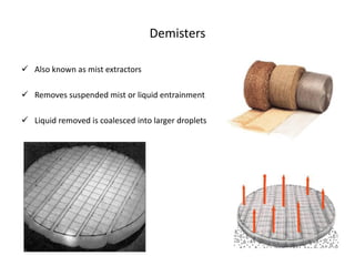
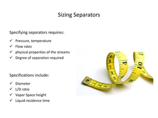
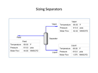
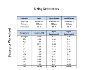
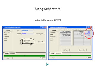
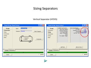
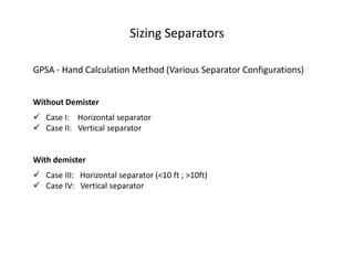
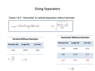
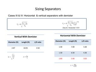
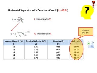
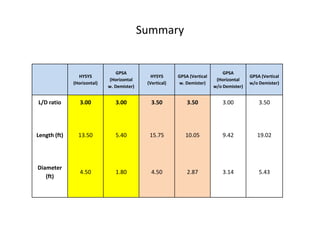
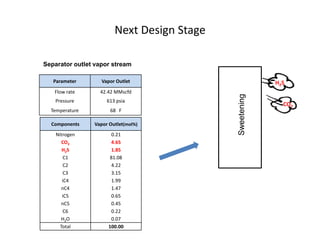
Separator Design


       Abita Antony
       Cyril Iyasele

  Natural Gas Engineering


      March 25, 2010
Outline

 Introduction

 Separator configurations

 Demisters

 Sizing separators

 Summary
Introduction to Phase Separation


 Physical separation of natural gas to its component phases

 The temperature and pressure of the gas dictates phases present

 Occurs in a pressure vessel provided for that purpose

 Mist extractors-wire mesh, vanes, or baffles- reduce liquid entrainment
Separator Configurations

 A separator is a vessel used to separate a mixed-phase stream into gas
  and liquid phases that are ‘’relatively’’ free of each other

 Principles used to achieve physical separation of gas and liquid include:
             •   momentum   •   gravity settling   •   coalescing


                                             Large volume of total fluid
                                             Large amount of dissolved gas


                                              High gas-liquid ratio
                                              Low total gas volume
Demisters

 Also known as mist extractors

 Removes suspended mist or liquid entrainment

 Liquid removed is coalesced into larger droplets
Sizing Separators

Specifying separators requires:
   Pressure, temperature
   Flow rates
   physical properties of the streams
   Degree of separation required


Specifications include:
   Diameter
   L/D ratio
   Vapor Space height
   Liquid residence time
Sizing Separators
Sizing Separators

                      Parameter        Feed       Vapor Outlet   Liquid Outlet
                       Flow rate    44 MMscfd     42.42 MMscfd   1.575 MMscfd
                       Pressure      613 psia        613 psia       613 psia
                      Temperature      68 F           68 F          68 F
Separator Worksheet


                                                     Vapor          Liquid
                      Components    Feed (mol%)
                                                  Outlet(mol%)   Outlet(mol%)
                       Nitrogen        0.20           0.21            0.00
                          CO2          4.50           4.65            0.49
                          H2 S         1.80           1.85            0.48
                          C1           78.31          81.08           3.51
                          C2           4.10           4.22            0.78
                          C3           3.10           3.15            1.70
                          iC4          2.00           1.99            2.30
                          nC4          1.50           1.47            2.29
                          iC5          0.70           0.65            2.14
                          nC5          0.50           0.45            1.90
                          C6           0.30           0.22            2.44
                         H2 O          3.00           0.07           81.97
                         Total        100.00         100.00         100.00
Sizing Separators

Computer Simulation Method


                                                 EOS: Peng-Robinson
Sizing Separators

Horizontal Separator (HYSYS)
Sizing Separators

Vertical Separator (HYSYS)
Sizing Separators

Hand Calculation Method
Sizing Separators

GPSA - Hand Calculation Method (Various Separator Configurations)


Without Demister
 Case I: Horizontal separator
 Case II: Vertical separator


With demister
 Case III: Horizontal separator (<10 ft ; >10ft)
 Case IV: Vertical separator
Sizing Separators

Cases I & II: Horizontal & vertical separators without demister


                                                  Horizontal Without Demister
     Vertical Without Demister
                                               Diameter (ft)   Length (ft)   L/D ratio
Diameter (ft)   Length (ft)   L/D ratio

                                                   2.50          11.80         4.72
    5.43          19.02         3.50

                                                   2.80          10.50         3.77


                                                   3.14           9.42         3.00
Sizing Separators
Cases III & IV: Horizontal & vertical separators with demister


                                                        Only for :Horizontal >10 ft


       Vertical With Demister                      Horizontal With Demister

                                             Diameter (ft)        Length (ft)         L/D ratio
Diameter (ft)   Length (ft)   L/D ratio

                                                 1.40                7.00               5.00
    2.87          10.05         3.50

                                                 1.50                6.50               4.36


                                                 1.80                5.40               3.03
Horizontal Separator with Demister- Case II ( L >10 ft )


                               L changes with Vt


                                                                               L/D ratio:
                                                                               b/w 3 ~ 5
                               Vt changes with L


assumed Length (ft)   Terminal Velocity (ft/s)     Diameter (ft)   L/D ratio
        L                       Vt                      Dv             r
       11                      1.45                    0.85          13.00
       12                      1.52                    0.74          16.25
       13                      1.59                    0.65          19.94
       14                      1.66                    0.58          24.11
       15                      1.72                    0.52          28.77
Summary


                                 GPSA                                          GPSA
                HYSYS                          HYSYS      GPSA (Vertical                   GPSA (Vertical
                             (Horizontal                                    (Horizontal
              (Horizontal)                   (Vertical)   w. Demister)                     w/o Demister)
                             w. Demister)                                  w/o Demister)


L/D ratio        3.00           3.00           3.50           3.50             3.00            3.50


Length (ft)     13.50           5.40          15.75          10.05             9.42           19.02


Diameter
                 4.50           1.80           4.50           2.87             3.14            5.43
   (ft)
Next Design Stage

Separator outlet vapor stream

   Parameter       Vapor Outlet                          H2 S
   Flow rate      42.42 MMscfd


                                            Sweetening
    Pressure         613 psia
                                                            CO2
  Temperature         68 F

  Components    Vapor Outlet(mol%)
    Nitrogen           0.21
       CO2            4.65
       H2S            1.85
        C1            81.08
        C2             4.22
        C3             3.15
       iC4             1.99
       nC4             1.47
       iC5             0.65
       nC5             0.45
        C6             0.22
      H2O              0.07
      Total          100.00
Thank you

Gas Plant Separator Design

  • 1.
    Separator Design Abita Antony Cyril Iyasele Natural Gas Engineering March 25, 2010
  • 2.
    Outline  Introduction  Separatorconfigurations  Demisters  Sizing separators  Summary
  • 3.
    Introduction to PhaseSeparation  Physical separation of natural gas to its component phases  The temperature and pressure of the gas dictates phases present  Occurs in a pressure vessel provided for that purpose  Mist extractors-wire mesh, vanes, or baffles- reduce liquid entrainment
  • 4.
    Separator Configurations  Aseparator is a vessel used to separate a mixed-phase stream into gas and liquid phases that are ‘’relatively’’ free of each other  Principles used to achieve physical separation of gas and liquid include: • momentum • gravity settling • coalescing Large volume of total fluid Large amount of dissolved gas High gas-liquid ratio Low total gas volume
  • 5.
    Demisters  Also knownas mist extractors  Removes suspended mist or liquid entrainment  Liquid removed is coalesced into larger droplets
  • 6.
    Sizing Separators Specifying separatorsrequires:  Pressure, temperature  Flow rates  physical properties of the streams  Degree of separation required Specifications include:  Diameter  L/D ratio  Vapor Space height  Liquid residence time
  • 7.
  • 8.
    Sizing Separators Parameter Feed Vapor Outlet Liquid Outlet Flow rate 44 MMscfd 42.42 MMscfd 1.575 MMscfd Pressure 613 psia 613 psia 613 psia Temperature 68 F 68 F 68 F Separator Worksheet Vapor Liquid Components Feed (mol%) Outlet(mol%) Outlet(mol%) Nitrogen 0.20 0.21 0.00 CO2 4.50 4.65 0.49 H2 S 1.80 1.85 0.48 C1 78.31 81.08 3.51 C2 4.10 4.22 0.78 C3 3.10 3.15 1.70 iC4 2.00 1.99 2.30 nC4 1.50 1.47 2.29 iC5 0.70 0.65 2.14 nC5 0.50 0.45 1.90 C6 0.30 0.22 2.44 H2 O 3.00 0.07 81.97 Total 100.00 100.00 100.00
  • 9.
    Sizing Separators Computer SimulationMethod EOS: Peng-Robinson
  • 10.
  • 11.
  • 12.
  • 13.
    Sizing Separators GPSA -Hand Calculation Method (Various Separator Configurations) Without Demister  Case I: Horizontal separator  Case II: Vertical separator With demister  Case III: Horizontal separator (<10 ft ; >10ft)  Case IV: Vertical separator
  • 14.
    Sizing Separators Cases I& II: Horizontal & vertical separators without demister Horizontal Without Demister Vertical Without Demister Diameter (ft) Length (ft) L/D ratio Diameter (ft) Length (ft) L/D ratio 2.50 11.80 4.72 5.43 19.02 3.50 2.80 10.50 3.77 3.14 9.42 3.00
  • 15.
    Sizing Separators Cases III& IV: Horizontal & vertical separators with demister Only for :Horizontal >10 ft Vertical With Demister Horizontal With Demister Diameter (ft) Length (ft) L/D ratio Diameter (ft) Length (ft) L/D ratio 1.40 7.00 5.00 2.87 10.05 3.50 1.50 6.50 4.36 1.80 5.40 3.03
  • 16.
    Horizontal Separator withDemister- Case II ( L >10 ft ) L changes with Vt L/D ratio: b/w 3 ~ 5 Vt changes with L assumed Length (ft) Terminal Velocity (ft/s) Diameter (ft) L/D ratio L Vt Dv r 11 1.45 0.85 13.00 12 1.52 0.74 16.25 13 1.59 0.65 19.94 14 1.66 0.58 24.11 15 1.72 0.52 28.77
  • 17.
    Summary GPSA GPSA HYSYS HYSYS GPSA (Vertical GPSA (Vertical (Horizontal (Horizontal (Horizontal) (Vertical) w. Demister) w/o Demister) w. Demister) w/o Demister) L/D ratio 3.00 3.00 3.50 3.50 3.00 3.50 Length (ft) 13.50 5.40 15.75 10.05 9.42 19.02 Diameter 4.50 1.80 4.50 2.87 3.14 5.43 (ft)
  • 18.
    Next Design Stage Separatoroutlet vapor stream Parameter Vapor Outlet H2 S Flow rate 42.42 MMscfd Sweetening Pressure 613 psia CO2 Temperature 68 F Components Vapor Outlet(mol%) Nitrogen 0.21 CO2 4.65 H2S 1.85 C1 81.08 C2 4.22 C3 3.15 iC4 1.99 nC4 1.47 iC5 0.65 nC5 0.45 C6 0.22 H2O 0.07 Total 100.00
  • 19.