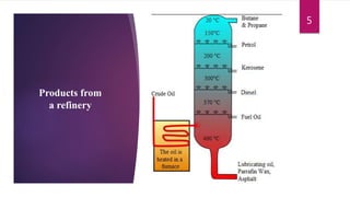
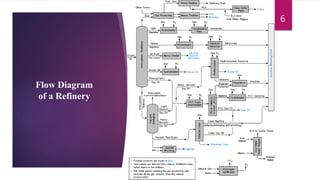
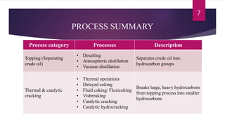
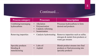
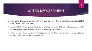
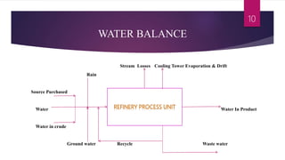
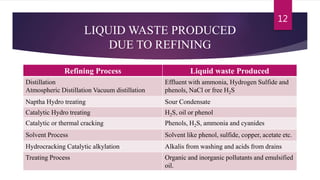
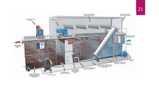
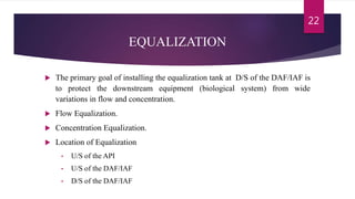
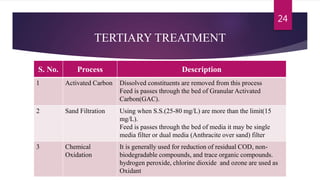
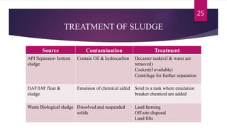
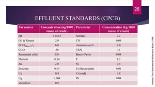
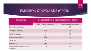
Guided By
Dr. Mrs Anjali K. Khambete
Associate Professor,
Department of Civil Engineering
Presented By
Tulsi Makwana
P17EN011
M-Tech (Environmental Engineering)
PETROLEUM REFINERIES
INTRODUCTION
 An oil refinery (petroleum refinery) is an industrial process plant where crude oil is
processed and refined into more useful products such as petroleum naphtha, gasoline,
diesel fuel, and asphalt base, heating oil, kerosene and liquefied petroleum gas, jet
fuel and fuel oils.
 Oil refineries are typically large, sprawling industrial complexes with extensive
piping running throughout, carrying streams of fluids between large chemical
processing units, such as distillation columns.
 As on 31 March 2016, there were 23 crude oil refineries in India, of which 18 were
state-owned, 3 were privately owned and 2 were joint ventures.
 India produced 243.551 MMT of petro products in 2016-17.
2
INTRODUCTION
 USA, China, Russia, Japan and India are the countries with the largest refinery
capacity in the world.
 Large volume of water is employed in refining processes, especially for cooling
systems, distillation, hydro treating, and desalting. Tank drains, equipment flushing,
surface water runoff and sanitary wastewater is also generated.
 The quantity of wastewaters generated and its characteristics depend on the process
configuration.
 As a general guide, approximately 3.5–5 cubic meters (m3
) of wastewater per ton of
crude is generated when cooling water is recycled.
3
Oil refineries
in India
4
Products from
a refinery
5
Flow Diagram
of a Refinery
6
PROCESS SUMMARY
Process category Processes Description
Topping (Separating
crude oil)
• Desalting
• Atmospheric distillation
• Vacuum distillation
Separates crude oil into
hydrocarbon groups
Thermal & catalytic
cracking
• Thermal operations
• Delayed coking
• Fluid coking/ Flexicoking
• Visbreaking
• Catalytic cracking
• Catalytic hydrocracking
Breaks large, heavy hydrocarbons
from topping process into smaller
hydrocarbons
7
Continued…
Process category Processes Description
Combining/rearranging
hydrocarbons
• Alkylation
• Polymerization
• Catalytic reforming
• Isomerization
Processes hydrocarbons to form
desired end products
Removing impurities • Catalytic hydrotreating Removes impurities such as sulfur,
nitrogen & metals from products or
waste gas streams
Specialty products
blending &
manufacturing
• Lube oil
• Asphalt
Blends product streams into final
products or final processing into
specialty products
8
WATER REQUIREMENT
 The water demand is up to 3 m3 of water for every ton of petroleum processed (US
EPA, 1980, 1982; WB, 1998).
 Almost 56% of this quantity is used in cooling systems, 16% in boiling systems, 19%
in production processes and the rest in auxiliary operations.
 The cooling waters are generally recycled, but the losses by evaporation are high, up
to 50% of the amount of the used water.
9
WATER BALANCE
Stream Losses Cooling Tower Evaporation & Drift
Rain
Source Purchased
Water Water In Product
Water in crude
Ground water Recycle Waste water
10
WASTE THROUGH REFINERY
 Refining process generates wastewater 0.4-1.6 times of the volume of crude oil
processed.
 Mixing of petroleum refinery wastewater into natural water sources affect the
environment and human health due to contamination of hydrocarbons, phenols
and dissolved minerals that are toxic in nature.
 The waters that are been in contact with petroleum and its derivatives contain oil,
hydrocarbons, phenols, sulfides, ammonia and large quantities of inorganic salts.
11
LIQUID WASTE PRODUCED
DUE TO REFINING
Refining Process Liquid waste Produced
Distillation
Atmospheric Distillation Vacuum distillation
Effluent with ammonia, Hydrogen Sulfide and
phenols, NaCl or free H2S
Naptha Hydro treating Sour Condensate
Catalytic Hydro treating H2S, oil or phenol
Catalytic or thermal cracking Phenols, H2S, ammonia and cyanides
Solvent Process Solvent like phenol, sulfide, copper, acetate etc.
Hydrocracking Catalytic alkylation Alkalis from washing and acids from drains
Treating Process Organic and inorganic pollutants and emulsified
oil.
12
REFINERY WASTEWATER EFFLUENT
CHARACTERISTICS
Parameter mg/L Parameter mg/L
TDS 2190 Calcium as CaCO3 610
TSS 29 Magnesium as CaCO3 116
COD 100 Sodium 387
Total kjeldahl Nitrogen 6.8 Barium 0.48
Ammonia – N 2.6 Iron 3.8
Phosphorous 0.97 Manganese 0.11
Carbonate Alkalinity 20 Strontium 2.4
Bi-Carbonate Alkalinity 323 Chloride 703
Silica 45 Sulfate 228
13
MAJOR WASTEWATER STREAMS
Wastewater Description
Desalter water
Water produced from washing the raw crude prior to topping
operations.
Sour water
Wastewater from steam stripping & fractionating operations
that comes into contact with the crude being processed.
Other process water
Wastewater from product washing, catalyst regeneration &
dehydrogenation reactions.
Spent caustic
Formed in extraction of acidic compounds from product
streams.
Tank bottoms
Bottom sediment and water settles to the bottom of tanks used
to store raw crude. The bottoms are periodically removed.
14
Continued…
Wastewater Description
Cooling tower
Once-through cooling tower water & cooling tower blowdown
to prevent build up of dissolved solids in closed-loop cooling
systems.
Condensate blowdown
Blowdown from boilers and steam generators to control build
up of dissolved solids.
Source water treatment
system
Source water must be treated prior to use in the refinery. Waste
streams may include water from sludge dewatering if lime
softening is used; ion exchange regeneration water; or reverse
osmosis wastewater.
Stormwater Process area and non-process area runoff from storm events.
Ballast water Ballast water from product tankers.
15
EFFLUENT TREATMENT
Slop Oil Slop Oil
Sludge Sludge
Effluent
Primary
oil
Separator
Sec. Oil
Separator
Clari-
floculator
Equali-
zation
Biological
Treatment
Tertiary
Treatment
16
Influent
OIL SEPARATOR
 Oil separators are used to treat the wastewater containing oil and oil bearing
sludge.
 Separators use the difference in specific gravity to allow heavier material to settle
below lighter liquids.
 Hydrocarbons that float on the surface are skimmed off, while the sludge that
settles to the bottom is removed periodically.
17
OIL SEPARATOR
1. Trash trap (inclined rods).
2. Oil retention baffles.
3. Flow distributors (vertical rods).
4. Oil layer
5. Slotted pipe skimmer.
6. Adjustable overflow weir.
7. Sludge sump.
8. Chain and flight scrapper.
18
SECONDARY OIL SEPERATOR
 The effluent from the primary oil/water separation step is sent for further oil and
fine solids removal to either a DAF (Dissolved Air Flotation) unit or an IAF
(Induced Air Flotation) unit.
 The first step in a DAF system is coagulation/ flocculation.
 Dispersed particles (oil/solids) are stabilized by negative electric charges on their
surfaces, causing them to repel each other
 To assist in the removal of colloidal particles from suspension, chemical
coagulation and flocculation are required.
 In a DAF system, part of the effluent is recycled, pressurized, saturated with air
and mixed with the incoming feed.
19
Continued…
20
21
EQUALIZATION
 The primary goal of installing the equalization tank at D/S of the DAF/IAF is
to protect the downstream equipment (biological system) from wide
variations in flow and concentration.
 Flow Equalization.
 Concentration Equalization.
 Location of Equalization
• U/S of the API
• U/S of the DAF/IAF
• D/S of the DAF/IAF
22
BIOLOGICAL TREATMENT
 Suspended Growth
• Activated Sludge Process
• Sequential Batch Reactor
• Membrane bioreactor technology
• Aerated lagoons
 Attached Growth
• Trickling Filter
• Rotating Biological Contractor
23
TERTIARY TREATMENT
S. No. Process Description
1 Activated Carbon Dissolved constituents are removed from this process
Feed is passes through the bed of Granular Activated
Carbon(GAC).
2 Sand Filtration Using when S.S.(25-80 mg/L) are more than the limit(15
mg/L).
Feed is passes through the bed of media it may be single
media filter or dual media (Anthracite over sand) filter
3 Chemical
Oxidation
It is generally used for reduction of residual COD, non-
biodegradable compounds, and trace organic compounds.
hydrogen peroxide, chlorine dioxide and ozone are used as
Oxidant
24
TREATMENT OF SLUDGE
Source Contamination Treatment
API Separator- bottom
sludge
Contain Oil & hydrocarbon Decanter tank(oil & water are
removed)
Cocker(if available)
Centrifuge for further separation
DAF/IAF float &
sludge
Emulsion of chemical aided Send to a tank where emulation
breaker chemical are added
Waste Biological sludge Dissolved and suspended
solids
Land farming
Off-site disposal
Land fills
25
HAP emissions from refineries
26
Green House Gas emissions from refineries
27
EFFLUENT STANDARDS (CPCB)
Parameter Concentration (kg/1000
tonne of crude)
Parameter Concentration (kg/1000
tonne of crude)
pH 6.0-8.5 Sulfides 0.2
Oil & Grease 2.0 CN 0.08
BOD3days, 27
o
C 6.0 Ammonia as N 6.0
COD 50 TKN 16
Suspended solid 8.0 Benzo-Pyrin 0.08
Phenols 0.14 P 1.2
Zn 2.0 Ni 0.4
Benzene 0.04 Cr(Hexavalent) 0.04
Cu 0.4 Cr(total) 0.8
Hg 0.004 Pb 0.04
Vanadium 0.8
28
Source:TheEnvironment(Protection)Rules,1986.
EMISSION STANDARDS (CPCB)
Parameter Concentration in mg/normal cubic meter
With Existing Instrument With Advance Instrument
Particulate matter(g) 10 05
Nitrogen Oxides (g) 350 250
Sulfur Oxides (g) 50 50
Carbon monoxide (g) 150 100
Ni+V (L) 5 5
H2S (L/G) 150 150
Sulfur content in liquid fuel
weight %
1.0 0.5
29
“
”
We won’t have a society if we
destroy the environment.!.
MARGARET MEAD
THANK YOU
30

Effluent from petroleum refineries

  • 1.
    Guided By Dr. MrsAnjali K. Khambete Associate Professor, Department of Civil Engineering Presented By Tulsi Makwana P17EN011 M-Tech (Environmental Engineering) PETROLEUM REFINERIES
  • 2.
    INTRODUCTION  An oilrefinery (petroleum refinery) is an industrial process plant where crude oil is processed and refined into more useful products such as petroleum naphtha, gasoline, diesel fuel, and asphalt base, heating oil, kerosene and liquefied petroleum gas, jet fuel and fuel oils.  Oil refineries are typically large, sprawling industrial complexes with extensive piping running throughout, carrying streams of fluids between large chemical processing units, such as distillation columns.  As on 31 March 2016, there were 23 crude oil refineries in India, of which 18 were state-owned, 3 were privately owned and 2 were joint ventures.  India produced 243.551 MMT of petro products in 2016-17. 2
  • 3.
    INTRODUCTION  USA, China,Russia, Japan and India are the countries with the largest refinery capacity in the world.  Large volume of water is employed in refining processes, especially for cooling systems, distillation, hydro treating, and desalting. Tank drains, equipment flushing, surface water runoff and sanitary wastewater is also generated.  The quantity of wastewaters generated and its characteristics depend on the process configuration.  As a general guide, approximately 3.5–5 cubic meters (m3 ) of wastewater per ton of crude is generated when cooling water is recycled. 3
  • 4.
  • 5.
  • 6.
  • 7.
    PROCESS SUMMARY Process categoryProcesses Description Topping (Separating crude oil) • Desalting • Atmospheric distillation • Vacuum distillation Separates crude oil into hydrocarbon groups Thermal & catalytic cracking • Thermal operations • Delayed coking • Fluid coking/ Flexicoking • Visbreaking • Catalytic cracking • Catalytic hydrocracking Breaks large, heavy hydrocarbons from topping process into smaller hydrocarbons 7
  • 8.
    Continued… Process category ProcessesDescription Combining/rearranging hydrocarbons • Alkylation • Polymerization • Catalytic reforming • Isomerization Processes hydrocarbons to form desired end products Removing impurities • Catalytic hydrotreating Removes impurities such as sulfur, nitrogen & metals from products or waste gas streams Specialty products blending & manufacturing • Lube oil • Asphalt Blends product streams into final products or final processing into specialty products 8
  • 9.
    WATER REQUIREMENT  Thewater demand is up to 3 m3 of water for every ton of petroleum processed (US EPA, 1980, 1982; WB, 1998).  Almost 56% of this quantity is used in cooling systems, 16% in boiling systems, 19% in production processes and the rest in auxiliary operations.  The cooling waters are generally recycled, but the losses by evaporation are high, up to 50% of the amount of the used water. 9
  • 10.
    WATER BALANCE Stream LossesCooling Tower Evaporation & Drift Rain Source Purchased Water Water In Product Water in crude Ground water Recycle Waste water 10
  • 11.
    WASTE THROUGH REFINERY Refining process generates wastewater 0.4-1.6 times of the volume of crude oil processed.  Mixing of petroleum refinery wastewater into natural water sources affect the environment and human health due to contamination of hydrocarbons, phenols and dissolved minerals that are toxic in nature.  The waters that are been in contact with petroleum and its derivatives contain oil, hydrocarbons, phenols, sulfides, ammonia and large quantities of inorganic salts. 11
  • 12.
    LIQUID WASTE PRODUCED DUETO REFINING Refining Process Liquid waste Produced Distillation Atmospheric Distillation Vacuum distillation Effluent with ammonia, Hydrogen Sulfide and phenols, NaCl or free H2S Naptha Hydro treating Sour Condensate Catalytic Hydro treating H2S, oil or phenol Catalytic or thermal cracking Phenols, H2S, ammonia and cyanides Solvent Process Solvent like phenol, sulfide, copper, acetate etc. Hydrocracking Catalytic alkylation Alkalis from washing and acids from drains Treating Process Organic and inorganic pollutants and emulsified oil. 12
  • 13.
    REFINERY WASTEWATER EFFLUENT CHARACTERISTICS Parametermg/L Parameter mg/L TDS 2190 Calcium as CaCO3 610 TSS 29 Magnesium as CaCO3 116 COD 100 Sodium 387 Total kjeldahl Nitrogen 6.8 Barium 0.48 Ammonia – N 2.6 Iron 3.8 Phosphorous 0.97 Manganese 0.11 Carbonate Alkalinity 20 Strontium 2.4 Bi-Carbonate Alkalinity 323 Chloride 703 Silica 45 Sulfate 228 13
  • 14.
    MAJOR WASTEWATER STREAMS WastewaterDescription Desalter water Water produced from washing the raw crude prior to topping operations. Sour water Wastewater from steam stripping & fractionating operations that comes into contact with the crude being processed. Other process water Wastewater from product washing, catalyst regeneration & dehydrogenation reactions. Spent caustic Formed in extraction of acidic compounds from product streams. Tank bottoms Bottom sediment and water settles to the bottom of tanks used to store raw crude. The bottoms are periodically removed. 14
  • 15.
    Continued… Wastewater Description Cooling tower Once-throughcooling tower water & cooling tower blowdown to prevent build up of dissolved solids in closed-loop cooling systems. Condensate blowdown Blowdown from boilers and steam generators to control build up of dissolved solids. Source water treatment system Source water must be treated prior to use in the refinery. Waste streams may include water from sludge dewatering if lime softening is used; ion exchange regeneration water; or reverse osmosis wastewater. Stormwater Process area and non-process area runoff from storm events. Ballast water Ballast water from product tankers. 15
  • 16.
    EFFLUENT TREATMENT Slop OilSlop Oil Sludge Sludge Effluent Primary oil Separator Sec. Oil Separator Clari- floculator Equali- zation Biological Treatment Tertiary Treatment 16 Influent
  • 17.
    OIL SEPARATOR  Oilseparators are used to treat the wastewater containing oil and oil bearing sludge.  Separators use the difference in specific gravity to allow heavier material to settle below lighter liquids.  Hydrocarbons that float on the surface are skimmed off, while the sludge that settles to the bottom is removed periodically. 17
  • 18.
    OIL SEPARATOR 1. Trashtrap (inclined rods). 2. Oil retention baffles. 3. Flow distributors (vertical rods). 4. Oil layer 5. Slotted pipe skimmer. 6. Adjustable overflow weir. 7. Sludge sump. 8. Chain and flight scrapper. 18
  • 19.
    SECONDARY OIL SEPERATOR The effluent from the primary oil/water separation step is sent for further oil and fine solids removal to either a DAF (Dissolved Air Flotation) unit or an IAF (Induced Air Flotation) unit.  The first step in a DAF system is coagulation/ flocculation.  Dispersed particles (oil/solids) are stabilized by negative electric charges on their surfaces, causing them to repel each other  To assist in the removal of colloidal particles from suspension, chemical coagulation and flocculation are required.  In a DAF system, part of the effluent is recycled, pressurized, saturated with air and mixed with the incoming feed. 19
  • 20.
  • 21.
  • 22.
    EQUALIZATION  The primarygoal of installing the equalization tank at D/S of the DAF/IAF is to protect the downstream equipment (biological system) from wide variations in flow and concentration.  Flow Equalization.  Concentration Equalization.  Location of Equalization • U/S of the API • U/S of the DAF/IAF • D/S of the DAF/IAF 22
  • 23.
    BIOLOGICAL TREATMENT  SuspendedGrowth • Activated Sludge Process • Sequential Batch Reactor • Membrane bioreactor technology • Aerated lagoons  Attached Growth • Trickling Filter • Rotating Biological Contractor 23
  • 24.
    TERTIARY TREATMENT S. No.Process Description 1 Activated Carbon Dissolved constituents are removed from this process Feed is passes through the bed of Granular Activated Carbon(GAC). 2 Sand Filtration Using when S.S.(25-80 mg/L) are more than the limit(15 mg/L). Feed is passes through the bed of media it may be single media filter or dual media (Anthracite over sand) filter 3 Chemical Oxidation It is generally used for reduction of residual COD, non- biodegradable compounds, and trace organic compounds. hydrogen peroxide, chlorine dioxide and ozone are used as Oxidant 24
  • 25.
    TREATMENT OF SLUDGE SourceContamination Treatment API Separator- bottom sludge Contain Oil & hydrocarbon Decanter tank(oil & water are removed) Cocker(if available) Centrifuge for further separation DAF/IAF float & sludge Emulsion of chemical aided Send to a tank where emulation breaker chemical are added Waste Biological sludge Dissolved and suspended solids Land farming Off-site disposal Land fills 25
  • 26.
    HAP emissions fromrefineries 26
  • 27.
    Green House Gasemissions from refineries 27
  • 28.
    EFFLUENT STANDARDS (CPCB) ParameterConcentration (kg/1000 tonne of crude) Parameter Concentration (kg/1000 tonne of crude) pH 6.0-8.5 Sulfides 0.2 Oil & Grease 2.0 CN 0.08 BOD3days, 27 o C 6.0 Ammonia as N 6.0 COD 50 TKN 16 Suspended solid 8.0 Benzo-Pyrin 0.08 Phenols 0.14 P 1.2 Zn 2.0 Ni 0.4 Benzene 0.04 Cr(Hexavalent) 0.04 Cu 0.4 Cr(total) 0.8 Hg 0.004 Pb 0.04 Vanadium 0.8 28 Source:TheEnvironment(Protection)Rules,1986.
  • 29.
    EMISSION STANDARDS (CPCB) ParameterConcentration in mg/normal cubic meter With Existing Instrument With Advance Instrument Particulate matter(g) 10 05 Nitrogen Oxides (g) 350 250 Sulfur Oxides (g) 50 50 Carbon monoxide (g) 150 100 Ni+V (L) 5 5 H2S (L/G) 150 150 Sulfur content in liquid fuel weight % 1.0 0.5 29
  • 30.
    “ ” We won’t havea society if we destroy the environment.!. MARGARET MEAD THANK YOU 30

Editor's Notes

  • #17 Slop Oil and Sludge Oil is reclaimed petroleum waste mixtures of oil, chemicals and water derived from a wide variety of processes in refineries or oil fields.