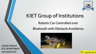
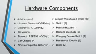
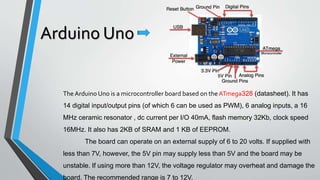
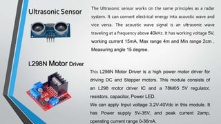
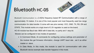
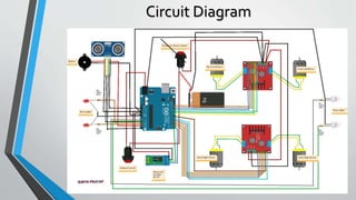
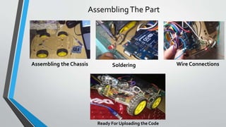
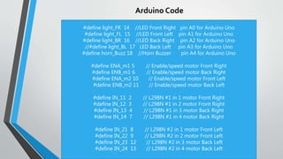
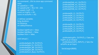
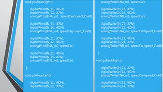
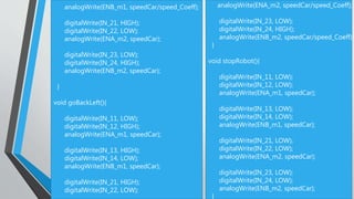
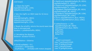
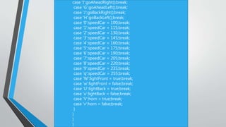
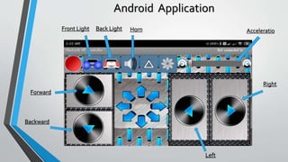
This is a robot car that can be remotely controlled using a Bluetooth terminal mobile application and has the capability to avoid the collision with the obstacles.
Arduino Interface LM35 MQTT Using UARTSanjay Kumar
Here we are implementing a Master-Slave Communication between two Arduino Uno Board with HC-05(Bluetooth) and Sending orreceiving data to and from an MQTT Client.
Presentation on embedded system and roboticsArpit Upadhyay
The document is a six-week summer training presentation on embedded systems and robotics submitted to Lovely Professional University. It summarizes the training, which was conducted at HP's nodal training center in Chandigarh, India. The training covered topics including embedded systems, robotics, microcontrollers, and a course project to build a computer-controlled robot using an AVR microcontroller and motor driver.
The MC1XDZC02-HP1 mounting card is designed to host DZC and DZXC series digital servo drives with a 60 amp peak current rating. It provides a compact assembly with readily accessible connectors and switches. The mounting card has connectors for signals, power, I/O, communication, and feedback and is used to integrate the digital servo drive into machines.
The MC1XDZPE01 mounting card is designed to host a DZE series DigiFlex® PerformanceTM digital servo drive. It provides a compact assembly with readily accessible connectors and switches. The mounting card mounts the servo drive, and provides connections for motor, power, signals, and communication via EtherCAT. It is suitable for prototyping or integrating the digital servo drive.
The MC1XDZ01 mounting card hosts DZ and DZX series digital servo drives from a single manufacturer. It provides signal and power connections to the drive and includes features like on-board signal conditioning and communication settings. The mounting card is compact and can be mounted on a DIN rail or screwed into place.
This document discusses connecting an Arduino board to an HC-05 Bluetooth module to enable Bluetooth control of an LED. It provides the hardware components, circuit schematic, Arduino code to control the LED based on Bluetooth input, and Processing code to build a GUI for controlling the LED remotely over Bluetooth. The Arduino code listens for Bluetooth input and turns the LED on or off, while the Processing code displays buttons to control the LED and receives status updates over Bluetooth.
In this presentation, Interfacing Bluetooth(HC-05) with Arduino is explained with some AT commands to configure and initialize the Bluetooth module(HC-05).
Code for Arduino:
#include <SoftwareSerial.h>
SoftwareSerial mySerial(10, 11); // RX, TX
void setup()
{
Serial.begin(9600);
pinMode(9,OUTPUT); digitalWrite(9,HIGH);
Serial.println("Enter AT commands:");
mySerial.begin(38400);
}
void loop()
{
if (mySerial.available())
Serial.write(mySerial.read());
if (Serial.available())
mySerial.write(Serial.read());
}
The DR101EE15A40LDC is a digital servo drive that controls brushed and brushless motors in torque, velocity, or position mode using space vector modulation. It features fully configurable digital and analog inputs and outputs, an RS232/485 interface, and extensive built-in protections. The drive operates motors from 60 to 400VDC and up to 15A continuous current while measuring feedback using encoders or Hall sensors.
This document describes an interactive vending machine project that uses an Arduino or PIC microcontroller. The machine uses various sensors and components like a proximity sensor, piezoelectric crystals, motor driver, LCD screen, and relay driver to provide two-way communication and make the machine more accessible for blind or visually impaired users. The machine will detect a user's presence, ask them to select an item, accept payment, dispense the product, and provide audio feedback at each step using voice logging and a speaker. The document outlines the hardware programming and lists the components required to build the interactive vending machine.
This document discusses interfacing Bluetooth with 8051 microcontrollers. It provides an overview of Bluetooth technology, describes how to connect a Bluetooth module to an 8051 microcontroller using serial communication, and includes code examples to transmit data between the two using Assembly and C programming languages.
The DR101EE30A40LDC is a digital servo drive that controls brushed and brushless motors. It features space vector modulation, PID control loops, configurable I/O including analog and digital signals, and isolated RS-232/485 communication. It operates in torque, velocity or position mode and includes setup software for configuration.
The document summarizes the pin configuration of the LPC2148 microcontroller. It has 45 GPIO pins across two ports, with Port 0 having 29 visible I/O pins and Port 1 having 16 visible pins. The microcontroller contains 19 different peripherals including USB D+ and D- lines, oscillator pins, RTC pins, ground pins, power supply pins, analog ground, analog power supply reference, and RTC power supply pin.
The DQ112EE15A40LDC is a digital servo drive with features such as space vector modulation, hall sensor and encoder feedback, isolated I/O, and a SynqNet interface. It provides motor control and I/O expansion for networked motion control applications. Key specifications include a 60-400VDC input, 15A peak current, and 20kHz switching frequency.
This document describes a voice recognition controlled robot that consists of two main parts: software and hardware. The software is designed using Embedded C and loaded onto a PIC16F877A microcontroller. Voice commands from a Bluetooth-connected smartphone are recognized and sent to control a motor via the microcontroller. The hardware includes the PIC microcontroller, Bluetooth module, motor driver, LCD display, and DC motor. The robot can be controlled remotely using voice commands from a smartphone via Bluetooth, providing a hands-free way to operate the robot.
The DQ111EE40A8BDC is a digital servo drive that controls brushed and brushless motors. It features space vector modulation for high efficiency and integrated SynqNet interface for networked motion control. It has inputs and outputs for motor commutation feedback, I/O signals, and analog command inputs. The drive provides torque control of the motor and protection from faults.
The DQ111EE30A40LDC is a digital servo drive for brushed and brushless motors. It features space vector modulation, a SynqNet interface, programmable I/O, and protection from overvoltage, undervoltage, overcurrent and overtemperature. It provides motor commutation from hall sensors or encoders and integrates a shunt regulator and status LED.
Touch Switch (Smart Switches) by arduino Project report fileimkanhaiyalal
The document provides details about the Arduino Mega 2560 microcontroller board. It has an ATmega2560 microcontroller, 54 digital input/output pins, 16 analog inputs, and is commonly used for beginner electronic projects and prototyping. The board can be powered via USB or an external power supply. It has 256KB of flash memory for storing code, 8KB of SRAM for variables, and communicates using serial communication and protocols like I2C and SPI. Programming the board involves using the Arduino IDE to compile code and upload it via the micro-USB connection.
The DQ111SE-H Series digital servo drives are designed to drive brushed and brushless servomotors. They employ Space Vector Modulation and vector control technology to achieve high bus voltage utilization and reduced heat dissipation. The drives feature dedicated digital and analog inputs and outputs as well as a SynqNet interface for networked motion control applications.
This document provides instructions for assembling and operating a robotic car kit. It includes a block diagram, descriptions of components like sensors and motors, assembly instructions, sample code to operate the robot, and troubleshooting tips. Contact information is provided at the end for technical support.
This document provides an introduction and overview of VIPA SLIO modular I/O systems. It describes the key features of SLIO including its compact design, labeling/diagnostic capabilities, flexible configuration, and high-performance. Application examples are given for packaging and machine automation. Ordering information is provided including module types, functions, and part numbers.
This document describes a Bluetooth controlled robot that can be operated using a mobile phone or PC. The robot contains a microcontroller, Bluetooth module, DC motors, motor driver, and power supply. The microcontroller is programmed to receive command signals from a Bluetooth application and control the motors accordingly to move the robot forward, backward, or turn. It explains the purpose and connection of each hardware component to allow remote control of the robot's movement via Bluetooth.
The DQ111EE Series is a digital servo drive that controls brushed and brushless motors. It features a SynqNet interface for networked motion control applications. The drive has inputs and outputs for motor commutation feedback, I/O control, and uses space vector modulation for efficient motor control. It is designed for easy setup and commissioning through Windows-based software.
PowerMate16 is a digital switching solution for transportation providing 16 MOSFET outputs, 16 digital inputs, and 6 analog inputs. It has connectors for power, input/output, and keypad. Features include over-current protection, reverse battery protection, and communication via CAN or OmniBus interfaces. The document provides detailed descriptions of the electrical features, connectors, input/output functionality, and revision history.
This document provides an overview of the robot car project for an embedded microprocessors systems course. It discusses the main systems and subsystems that will be developed, including the power supply, visual sensors, motors, and potential wireless enhancements. It also outlines the basic operation of the robotic car, describing how it will follow a 1-inch wide black centerline track using infrared proximity sensors to detect the line and motors controlled by a microcontroller to steer itself along the track. Testing plans are presented for each subsystem as well as overall system operation.
The presentation summarized OPAL-RT's new hardware products for real-time simulation, including the OP5607 expansion unit which uses a Virtex-7 FPGA and provides 8 Type-B mezzanine slots and 16 high-speed SFP optical links. The OP7000 is a 6U chassis with a Virtex-6 FPGA that supports 8 Type-B mezzanines on the front and 32 Type-E mezzanines on the back. Internal mezzanine modules like Type-B and Type-E were also described which provide functions including analog I/O, digital I/O, and signal conditioning.
The MC1XDZPC01 mounting card is designed to host DZCANTU series DigiFlex digital servo drives. It provides connectors for motor, power, signals, feedback and communication. The mounting card has terminals and connectors to integrate the servo drive and connect feedback devices, I/O and communication via CANopen or USB. Switch settings and jumpers configure the CANopen node ID, bit rate and termination for the network communication.
Obstacle detection Robot using Ultrasonic Sensor and Arduino UNOSanjay Kumar
This document describes how to build an obstacle detection robot using an Arduino UNO, ultrasonic sensor, and motor driver module. It explains the components used, including the Arduino, ultrasonic sensor to detect obstacles from 2-400cm away, and an L298N motor driver module to control DC motors. It provides details on connecting the components, programming the ultrasonic sensor to trigger and receive echo signals to determine distances, and controlling the motor's direction depending on detected obstacles to help the robot navigate. Code and more details are available at the provided GitHub link.
The document describes the design of an automated guided vehicle (AGV) that can avoid collisions with obstacles. The AGV uses infrared LEDs and receivers connected to a microcontroller to detect obstacles on its path and signals the motors to change direction accordingly. Key components include a chassis, motors, a microcontroller, motor driver, power supply and infrared sensors. The microcontroller is programmed using AVR Studio to control the motor directions based on input from the infrared sensors to navigate around any obstacles.
This document describes an automatic metro train system that shuttles between stations without a driver. The train stops automatically at stations using IR sensors and the doors open for a set time to allow passengers on and off. It counts passengers and has a display to show occupancy. The movement between stations is controlled by a motor driver and Arduino. It alerts passengers with a buzzer before closing doors or starting. The system could be enhanced to display train status and use voice announcements.
The document describes an obstacle avoiding robot created by four group members using an Arduino UNO, ultrasonic sensor, DC motor driver, and connecting wires. The robot senses obstacles in its path using the ultrasonic sensor, avoids obstacles by reversing or turning, and resumes moving forward once the path is clear. The robot's program uses the ultrasonic sensor readings to determine its speed and maneuvering.
This document provides an overview of Arduino programming concepts including:
- Microcontrollers contain a CPU, memory, input/output pins and other peripherals on a single integrated circuit.
- Arduino is an open-source electronics platform with a microcontroller, pins to connect circuits, and software to program it.
- The core Arduino functions include setup(), loop(), pinMode(), digitalWrite(), digitalRead(), analogWrite(), analogRead(), and delay().
- Examples demonstrate blinking LEDs, reading input, using conditions and loops, arrays, LCD displays, and controlling servo motors.
- Arduino programming provides an accessible way to learn embedded systems and interact with circuits.
Aircraft Anti collision system using ZIGBEE CommunicationPavanKalyan314
Documentation for the Exact title which I given.
In these document you will get whole information regarding to our project which I uploaded as ppt presentation.
If you need code for these project mail us to pavanslucky341@gmail.com
Thankyou.
This document is a project report submitted by four students to their professor for an Arduino-based Windows remote control project. The report includes an abstract, introduction to Arduino, details about the Arduino board and ATmega328 microcontroller, circuit diagram and working, software used, and testing conducted. It acknowledges the sources that helped in completing the project.
WIRELESS GESTURED CONTROLLED ROBOT USING ACCELEROMETERLOKENDAR KUMAR
This document describes a wireless gesture controlled robot that uses an accelerometer. The robot consists of a transmitting device worn on the hand that detects gestures via an accelerometer. The data is encoded and transmitted to a receiving unit connected to a microcontroller and motors. The microcontroller processes the encoded data and controls the motors to move the robot forward, backward, left or right depending on the detected hand gesture. The system allows controlling a robot's movement through wireless hand gestures without physical buttons or controls.
This document describes a Bluetooth controlled RC car using an Arduino. The key components include an Arduino Nano, motor shield, HC-05 Bluetooth module, DC motors, batteries, and other equipment. An Android application was developed to control the car remotely via buttons that send Bluetooth signals to the Arduino. The Arduino code interprets the signals to control the motor shield and drive the motors forward, backward, left, or right. The project aims to provide a low-cost educational robotics platform for students to experiment with.
The document describes the design and components of a remote-controlled spy robot. It has two main sections: 1) the remote control section, which uses an HT12E encoder and HT12D decoder to control the robot via radio signals from a wireless remote controller. 2) The video transmission section uses a wireless CCD camera powered by a 12V battery to capture video that is transmitted to a remote receiver via radio signals. The robot can be controlled remotely to move forward, backward, left, or right using two 12V gear motors and an L293D motor driver circuit.
This document describes a project to control a car's orientation through hand gestures detected by an MPU6050 gyroscope module. An Arduino Nano reads the hand movements from the MPU6050 and sends wireless control signals to a receiver using an RF module. The receiver decodes the signals using an HT12D decoder and drives two DC motors with an L293D motor driver to control the car's orientation based on the hand gestures. Block diagrams and brief descriptions of the main components - Arduino Nano, MPU6050 gyroscope, RF transmission modules, motor driver, and decoders - are provided.
Abstract : In the present study, innovative idea of touchpad controlled vehicle and its real life implication is
described. Generally in such system touchpad is interfaced with ADC [0808/MCP 3208] which gives the coordinates
of the points touch by the user on touchpad. But in this research work Programmable
Intercombination Circuit (PIC) [18F4550/18C4550] is used purposefully instead of ADC as input signal were
in analog which required converting into digital signal. PIC can be used to interface touchpad and also perform
serial port programming far better than ADC. PIC gives output to 8051 microcontroller which uses keil
software program in C for input and output programming. Test drive was done to crosscheck the performance
of touchpad as well as vehicle and it was observed that car was running at corresponding given location
directed by touchpad at al instants.
Keywords - Touch screen, PIC 18F4550, Motor driverL293D, RF Transmitter & Receiver, Keil software.
In the present study, innovative idea of touchpad controlled vehicle and its real life implication is
described. Generally in such system touchpad is interfaced with ADC [0808/MCP 3208] which gives the coordinates
of the points touch by the user on touchpad. But in this research work Programmable
Intercombination Circuit (PIC) [18F4550/18C4550] is used purposefully instead of ADC as input signal were
in analog which required converting into digital signal. PIC can be used to interface touchpad and also perform
serial port programming far better than ADC. PIC gives output to 8051 microcontroller which uses keil
software program in C for input and output programming. Test drive was done to crosscheck the performance
of touchpad as well as vehicle and it was observed that car was running at corresponding given location
directed by touchpad at al instants.
This document describes a student project to build a firefighting robot using an Arduino microcontroller. A group of electrical engineering students will present their project, which uses flame sensors to detect fire and a water pump to extinguish flames. The robot is able to autonomously sense and move towards a fire source, then activate the water pump. The presentation outlines the robot's components, circuit diagram, materials used, and working mechanism to demonstrate how the robot can help fight fires safely.
This document describes how to build a Bluetooth controlled robot using an Arduino Uno, HC-05 Bluetooth module, and L298N motor driver. The circuit connects the Bluetooth module to transmit movement commands from an Android app to the Arduino. The Arduino code controls the motor driver and motors to move the robot forward, backward, left and right based on the Bluetooth data. The robot has applications for surveillance, military use, assistive devices, and home automation.
IRJET- Automated Elevator-An Attentive Elevator to Elevate using Speech Recog...IRJET Journal
This document summarizes a student project to create an automated elevator that can be operated using voice commands. It includes:
1) An introduction describing the motivation to help people with disabilities operate elevators independently using voice recognition.
2) A block diagram and description of the system components including an Arduino microcontroller, Bluetooth module, sensors, LCD display and motor driver.
3) Details of the voice recognition module and how it converts voices into commands to control the elevator motor.
4) The proposed design uses an Arduino board to integrate the voice module and control the motor and display based on voice commands.
This document provides a 3-page datasheet for the SilverDust D2-IG8 servo controller/driver from QuickSilver Controls. It can control NEMA 11, 17, and 23 frame servomotors with high torque. Key features include 8 isolated digital I/O, 7 LVTTL I/O, CANopen interface, optional Ethernet connectivity, 32k of non-volatile memory, electronic gearing/camming capabilities, and compatibility with QCI motors and encoders. The document provides details on electrical specifications, mechanical dimensions, environmental specifications, and connector pinouts.
IRJET- Intelligent Security and Monitoring System for VehicleIRJET Journal
This document describes an intelligent security and monitoring system for vehicles that uses GPS and GSM technologies. The system detects vehicle accidents using a vibration sensor and sends SMS alerts to authorities to request immediate help. It also tracks the vehicle's location using GPS. The system is implemented using microcontrollers and sensors. When an accident is detected, the vibration readings exceed a threshold and the system takes action by sending SMS messages with the vehicle's location to get help quickly.
This document discusses automating an office environment using various sensors. It describes using RFID cards to automatically identify and greet employees upon entry. Motion detectors and a flame sensor are used for energy saving, automatic control of electronics, and fire safety. The objectives are to create a secure, safe working environment with automatic door control, lighting/device control based on presence detection, and fire alerts. Required hardware includes an Arduino, RFID components, sensors, and display. Software includes the Arduino IDE. Detailed descriptions of the Arduino, servo motor, and flame sensor components are also provided.
Contactless digital tachometer using microcontroller IJECEIAES
This document describes a contactless digital tachometer that uses an Arduino microcontroller, infrared sensor, and LCD display. The tachometer counts the number of rotations of a motor shaft using an IR transmitter and receiver without direct contact. It displays the revolutions per minute (RPM) measurement on an LCD screen. The Arduino microcontroller implements the RPM calculation from the IR sensor pulses and controls the LCD output. The tachometer provides contactless RPM measurement for motors in difficult to reach locations.
Similar to Robotic Car Controlled over Bluetooth with Obstacle Avoidance (20)
Blood finder application project report (1).pdfKamal Acharya
Blood Finder is an emergency time app where a user can search for the blood banks as
well as the registered blood donors around Mumbai. This application also provide an
opportunity for the user of this application to become a registered donor for this user have
to enroll for the donor request from the application itself. If the admin wish to make user
a registered donor, with some of the formalities with the organization it can be done.
Specialization of this application is that the user will not have to register on sign-in for
searching the blood banks and blood donors it can be just done by installing the
application to the mobile.
The purpose of making this application is to save the user’s time for searching blood of
needed blood group during the time of the emergency.
This is an android application developed in Java and XML with the connectivity of
SQLite database. This application will provide most of basic functionality required for an
emergency time application. All the details of Blood banks and Blood donors are stored
in the database i.e. SQLite.
This application allowed the user to get all the information regarding blood banks and
blood donors such as Name, Number, Address, Blood Group, rather than searching it on
the different websites and wasting the precious time. This application is effective and
user friendly.
Levelised Cost of Hydrogen (LCOH) Calculator ManualMassimo Talia
The aim of this manual is to explain the
methodology behind the Levelized Cost of
Hydrogen (LCOH) calculator. Moreover, this
manual also demonstrates how the calculator
can be used for estimating the expenses associated with hydrogen production in Europe
using low-temperature electrolysis considering different sources of electricity
DEEP LEARNING FOR SMART GRID INTRUSION DETECTION: A HYBRID CNN-LSTM-BASED MODELijaia
As digital technology becomes more deeply embedded in power systems, protecting the communication
networks of Smart Grids (SG) has emerged as a critical concern. Distributed Network Protocol 3 (DNP3)
represents a multi-tiered application layer protocol extensively utilized in Supervisory Control and Data
Acquisition (SCADA)-based smart grids to facilitate real-time data gathering and control functionalities.
Robust Intrusion Detection Systems (IDS) are necessary for early threat detection and mitigation because
of the interconnection of these networks, which makes them vulnerable to a variety of cyberattacks. To
solve this issue, this paper develops a hybrid Deep Learning (DL) model specifically designed for intrusion
detection in smart grids. The proposed approach is a combination of the Convolutional Neural Network
(CNN) and the Long-Short-Term Memory algorithms (LSTM). We employed a recent intrusion detection
dataset (DNP3), which focuses on unauthorized commands and Denial of Service (DoS) cyberattacks, to
train and test our model. The results of our experiments show that our CNN-LSTM method is much better
at finding smart grid intrusions than other deep learning algorithms used for classification. In addition,
our proposed approach improves accuracy, precision, recall, and F1 score, achieving a high detection
accuracy rate of 99.50%.
Impartiality as per ISO /IEC 17025:2017 StandardMuhammadJazib15
This document provides basic guidelines for imparitallity requirement of ISO 17025. It defines in detial how it is met and wiudhwdih jdhsjdhwudjwkdbjwkdddddddddddkkkkkkkkkkkkkkkkkkkkkkkwwwwwwwwwwwwwwwwwwwwwwwwwwwwwwwwwwwwwwwwwwwwwwwwwwwwwwwwwwwwwwwwwwwwwwwwwwwwwwwwwwwwwwwwwwwwwwwwwwwwwwwwwwwwwwwwwwwwwwwwwwwwwwwwwwwwwwwwwwwwwwwwwwwwwwwwwioiiiiiiiiiiiii uwwwwwwwwwwwwwwwwhe wiqqqqqqqqqqqqqqqqqqqqqqqqqqqqqqqqqqqqqqqqqqqqqqqqqqqqqqqqqqqqqqqqqqqqqqqqqqqqqqqqqqqqqqqqqqqqqqqqqqqqqqqqqqqqqqqqqqqqqqqqqqqqqqqqqqqqqqqqqqqqqqqqqqqqqqqqqqqqqqqqqqqqqqqqqqqqqqqqqqqqqqqqqqqqqqqqqqq gbbbbbbbbbbbbb owdjjjjjjjjjjjjjjjjjjjj widhi owqqqqqqqqqqqqqqqqqqqqqqqqqqqqqqqqqq uwdhhhhhhhhhhhhhhhhhhhhhhhhhhhhhhhhhhhhhhhhhhhhhhhhhhhhhhhhhhhhhhhhhhhhhhhhhhhhhhhhhhhhhhhhhhhhhhhhhhhhhhhhhhhhhhhhhhhhhhhhhhhhhhhhhhhhhhhhhhhhhhhhhhhhhhhhhhhhhhhhhhhhhhwqiiiiiiiiiiiiiiiiiiiiiiiiiiiiw0pooooojjjjjjjjjjjjjjjjjjjjjjjjjjjjjjjjjjjjjjjjjjjjjjjjjjjjjj whhhhhhhhhhh wheeeeeeee wihieiiiiii wihe
e qqqqqqqqqqeuwiiiiiiiiiiiiiiiiiiiiiiiiiiiiiiiiiiiiiiiiiiiiiiiiiiiiiiiiiiiiiiiiiiiiiiiiiiiiiiiiiiiiiiiiiiiiiiiiiiiiiiiiiiiiiiiiiiiiiiiiiiiiiiiiiiiiiiiiiiiiiiiiiiiiiiiiiiiiiiiiiiiiiiiiiiiiiiiiiiiiiiiiiiiiiiiiiiiiiiiiiiiiiiiiiiiiiiiiiiiiiiiiiiiiiiiiiiiiiiiiiiiiiiiiiiiiiiiiiiiiiiiiiiiiiiiiiiiiiiiiiiiiiiiiiiiiiiiiiiiiiiiiiiiiiiiiiqw dddddddddd cccccccccccccccv s w c r
cdf cb bicbsad ishd d qwkbdwiur e wetwwwwwwwwwwwwwwwwwwwwwwwwwwwwwwwwwwwwwwwwwwwwwwwwwwwwwwwwwwwwwwwwwwwwww w
dddddddddddddddddddddddddddddddddddddddddddddddddddddddddddddddddddddddddddddddddddddddddddddddddddddddddddfffffffffffffffffffffffffffffffffffffffffffffffffffffffffffffffffffffffffffffffffffffffffffffffffffffffffffffffffffffffffffffffffffffffffffffffffffffffffffffffffffffffffffffffffffffffffffffffffffffffffffffffffffffw
uuuuhhhhhhhhhhhhhhhhhhhhhhhhe qiiiiiiiiiiiiiiiiiiiiiiiiiiiiiiiiiiiiiiiiiiiiiiiiiiiiiiiiiiiiiii iqqqqqqqqqqqqqqqqqqqqqqqqqqqqqqqqqqqqqqqqqqqqqqqqqqqqqqqqqqqqqqqqqqqqqqqqqqqqqqqqqqqqqqqqqqqqqqqqqqqqqqqqqqqqqqqqqqqqqqqqqqqqqqqqqqqqq eeeeeeeeeeeeeeeeeeeeeeeeeeeeeeeeeeeeeeeeeeeeeeeeeeeeeeeeeeeeeeeeeeeeeeeeeeeeeeeeeeeeeeeeeeeeeeeeee qqqqqqqqqqqqqqqqqqqqqqqqqqqqqqqqqqqqqqqqqqqqqqqqqqqqqqqqqqqqqqqqqqqqqqqqqqqqqqqqqqqqqqqqqqqqqqqqqqqqqqqqqqqqqqccccccccccccccccccccccccccccccccccccccccccccccccccccccccccccc ccccccccccccccccccccccccccccccccccc bbbbbbbbbbbbbbbbbbbbbbbbbbbbbbbbbbbbbbbbbbbbbbbbbbbbbbbbbbbbbbbbbbbbbbbbbbbbbbbbu uuuuuuuuuuuuuuuuuuuuuuuuuuuuuuuuuuuuuuuuuuuuuuuuuuuuuuuuuuuuuuuuuuuuuuuuuuuuuuuuuuuuuuuuuuuuuuuuuuuuuuuuuuuuuuuuuuuuuuuuuuuuuuuuuuuuuuuuuuuuuuuuuuuuuuuuuum
m
m mmmmmmmmmmmmmmmmmmmmmmmmmmmmmmmmmmmmmmmmmmmmmmmmmmmmmmmmmmmmmmmmmmmmmmmmmmmmmmmmmmmmmmmmmmmm m i
g i dijsd sjdnsjd ndjajsdnnsa adjdnawddddddddddddd uw
A high-Speed Communication System is based on the Design of a Bi-NoC Router, ...DharmaBanothu
The Network on Chip (NoC) has emerged as an effective
solution for intercommunication infrastructure within System on
Chip (SoC) designs, overcoming the limitations of traditional
methods that face significant bottlenecks. However, the complexity
of NoC design presents numerous challenges related to
performance metrics such as scalability, latency, power
consumption, and signal integrity. This project addresses the
issues within the router's memory unit and proposes an enhanced
memory structure. To achieve efficient data transfer, FIFO buffers
are implemented in distributed RAM and virtual channels for
FPGA-based NoC. The project introduces advanced FIFO-based
memory units within the NoC router, assessing their performance
in a Bi-directional NoC (Bi-NoC) configuration. The primary
objective is to reduce the router's workload while enhancing the
FIFO internal structure. To further improve data transfer speed,
a Bi-NoC with a self-configurable intercommunication channel is
suggested. Simulation and synthesis results demonstrate
guaranteed throughput, predictable latency, and equitable
network access, showing significant improvement over previous
designs
Tools & Techniques for Commissioning and Maintaining PV Systems W-Animations ...Transcat
Join us for this solutions-based webinar on the tools and techniques for commissioning and maintaining PV Systems. In this session, we'll review the process of building and maintaining a solar array, starting with installation and commissioning, then reviewing operations and maintenance of the system. This course will review insulation resistance testing, I-V curve testing, earth-bond continuity, ground resistance testing, performance tests, visual inspections, ground and arc fault testing procedures, and power quality analysis.
Fluke Solar Application Specialist Will White is presenting on this engaging topic:
Will has worked in the renewable energy industry since 2005, first as an installer for a small east coast solar integrator before adding sales, design, and project management to his skillset. In 2022, Will joined Fluke as a solar application specialist, where he supports their renewable energy testing equipment like IV-curve tracers, electrical meters, and thermal imaging cameras. Experienced in wind power, solar thermal, energy storage, and all scales of PV, Will has primarily focused on residential and small commercial systems. He is passionate about implementing high-quality, code-compliant installation techniques.
Null Bangalore | Pentesters Approach to AWS IAMDivyanshu
#Abstract:
- Learn more about the real-world methods for auditing AWS IAM (Identity and Access Management) as a pentester. So let us proceed with a brief discussion of IAM as well as some typical misconfigurations and their potential exploits in order to reinforce the understanding of IAM security best practices.
- Gain actionable insights into AWS IAM policies and roles, using hands on approach.
#Prerequisites:
- Basic understanding of AWS services and architecture
- Familiarity with cloud security concepts
- Experience using the AWS Management Console or AWS CLI.
- For hands on lab create account on [killercoda.com](https://killercoda.com/cloudsecurity-scenario/)
# Scenario Covered:
- Basics of IAM in AWS
- Implementing IAM Policies with Least Privilege to Manage S3 Bucket
- Objective: Create an S3 bucket with least privilege IAM policy and validate access.
- Steps:
- Create S3 bucket.
- Attach least privilege policy to IAM user.
- Validate access.
- Exploiting IAM PassRole Misconfiguration
-Allows a user to pass a specific IAM role to an AWS service (ec2), typically used for service access delegation. Then exploit PassRole Misconfiguration granting unauthorized access to sensitive resources.
- Objective: Demonstrate how a PassRole misconfiguration can grant unauthorized access.
- Steps:
- Allow user to pass IAM role to EC2.
- Exploit misconfiguration for unauthorized access.
- Access sensitive resources.
- Exploiting IAM AssumeRole Misconfiguration with Overly Permissive Role
- An overly permissive IAM role configuration can lead to privilege escalation by creating a role with administrative privileges and allow a user to assume this role.
- Objective: Show how overly permissive IAM roles can lead to privilege escalation.
- Steps:
- Create role with administrative privileges.
- Allow user to assume the role.
- Perform administrative actions.
- Differentiation between PassRole vs AssumeRole
Try at [killercoda.com](https://killercoda.com/cloudsecurity-scenario/)
Open Channel Flow: fluid flow with a free surfaceIndrajeet sahu
Open Channel Flow: This topic focuses on fluid flow with a free surface, such as in rivers, canals, and drainage ditches. Key concepts include the classification of flow types (steady vs. unsteady, uniform vs. non-uniform), hydraulic radius, flow resistance, Manning's equation, critical flow conditions, and energy and momentum principles. It also covers flow measurement techniques, gradually varied flow analysis, and the design of open channels. Understanding these principles is vital for effective water resource management and engineering applications.
Robotic Car Controlled over Bluetooth with Obstacle Avoidance
1. KIET Group of Institutions
Robotic Car Controlled over
Bluetooth with Obstacle Avoidance
SURYA PRATAP
ECE DEPARTMENT
1900290310175 Ph..7500613027
2. Introduction
Robotic is the branch of electrical engineering,
mechanical engineering and computer science that deals
with the design, construction, operation, and application of
robot, as well as computer system for their control, sensory
feedback, and information processing.
This is a robot car that can be remotely controlled using a
Bluetooth terminal mobile application and has the
capability to avoid the collision with the obstacles.
3. Hardware Components
Arduino Uno (1)
Ultrasonic Sensor-HC-SR04 (1)
Motor Driver IC-L298N (2)
Dc Motor (4)
Bluetooth REES52 HC-05 (1)
Car Chassis (4)
12v Rechargeable Battery (1)
Jumper Wires Male Female (30)
Switch (2)
Passive Buzzer (1)
Red and Blue LED (5)
Charging Female Switch (1)
Resistance 220ohm (5)
Diode (2)
4. Arduino Uno
The Arduino Uno is a microcontroller board based on the ATmega328 (datasheet). It has
14 digital input/output pins (of which 6 can be used as PWM), 6 analog inputs, a 16
MHz ceramic resonator , dc current per I/O 40mA, flash memory 32Kb, clock speed
16MHz. It also has 2KB of SRAM and 1 KB of EEPROM.
The board can operate on an external supply of 6 to 20 volts. If supplied with
less than 7V, however, the 5V pin may supply less than 5V and the board may be
unstable. If using more than 12V, the voltage regulator may overheat and damage the
board. The recommended range is 7 to 12V.
5. Ultrasonic Sensor
The Ultrasonic sensor works on the same principles as a radar
system. It can convert electrical energy into acoustic wave and
vice versa. The acoustic wave signal is an ultrasonic wave
traveling at a frequency above 40kHz. It has working voltage 5V,
working current 15mA, Max range 4m and Min range 2cm ,
Measuring angle 15 degree.
L298N Motor Driver
This L298N Motor Driver is a high power motor driver for
driving DC and Stepper motors. This module consists of
an L298 motor driver IC and a 78M05 5V regulator,
resistors, capacitor, Power LED.
We can apply Input voltage 3.2V-40Vdc in this module. It
has Power supply 5V-35V, and peak current 2amp,
operating current range 0-36mA.
6. Bluetooth HC-05
Bluetooth Communication is a 2.4GHz frequency based RF Communication with a range of
approximately 10 meters. It is one of the most popular and most frequently used low range
communication for data transfer. It come with sex pins namely: VCC, GND, TX, RX, EN and
STATE. This module works on a logic level of 3.3V regulator is used on the board.
HC-05 module has Baud rate: 9600 with 8 data bits, no parity and 1 stop bit.
Module can be configured in two modes of operation:
In Command Mode, At commands for configuring various settings and parameter of
the module like get firmware information, change UART baud rate , set it as either
master or slave.
In Data Mode, In this mode, the module is used for communication with other
Bluetooth device example data transfer happens in this mode.
9. #define light_FR 14 //LED Front Right pin A0 for Arduino Uno
#define light_FL 15 //LED Front Left pin A1 for Arduino Uno
#define light_BR 16 //LED Back Right pin A2 for Arduino Uno
//#define light_BL 17 LED Back Left pin A3 for Arduino Uno
#define horn_Buzz 18 //Horn Buzzer pin A4 for Arduino Uno
#define ENA_m1 5 // Enable/speed motor Front Right
#define ENB_m1 6 // Enable/speed motor Back Right
#define ENA_m2 10 // Enable/speed motor Front Left
#define ENB_m2 11 // Enable/speed motor Back Left
#define IN_11 2 // L298N #1 in 1 motor Front Right
#define IN_12 3 // L298N #1 in 2 motor Front Right
#define IN_13 4 // L298N #1 in 3 motor Back Right
#define IN_14 7 // L298N #1 in 4 motor Back Right
#define IN_21 8 // L298N #2 in 1 motor Front Left
#define IN_22 9 // L298N #2 in 2 motor Front Left
#define IN_23 12 // L298N #2 in 3 motor Back Left
#define IN_24 13 // L298N #2 in 4 motor Back Left
Arduino Code
10. int command; //Int to store app command
state.
int speedCar = 100;
int speedCarM = 95;// 50 - 255.
int speed_Coeff = 4;
const int trigPin = A5;
const int echoPin = A3;
// defines variables
long duration;
int distance;
int safetyDistance;
boolean lightFront = false;
boolean lightBack = false;
boolean horn = false;
void setup() {
pinMode(light_FR, OUTPUT);
pinMode(light_FL, OUTPUT);
pinMode(light_BR, OUTPUT);
pinMode(horn_Buzz, OUTPUT);
pinMode(ENA_m1, OUTPUT);
pinMode(ENB_m1, OUTPUT);
pinMode(ENA_m2, OUTPUT);
pinMode(ENB_m2, OUTPUT);
pinMode(IN_11, OUTPUT);
pinMode(IN_12, OUTPUT);
pinMode(IN_13, OUTPUT);
pinMode(IN_14, OUTPUT);
pinMode(IN_21, OUTPUT);
pinMode(IN_22, OUTPUT);
pinMode(IN_23, OUTPUT);
pinMode(IN_24, OUTPUT);
pinMode(trigPin, OUTPUT); // Sets the
trigPin as an Output
pinMode(echoPin, INPUT); // Sets the
echoPin as an Input
Serial.begin(9600);
}
15. void loop(){
// Clears the trigPin
digitalWrite(trigPin, LOW);
delayMicroseconds(2);
// Sets the trigPin on HIGH state for 10 micro
seconds
digitalWrite(trigPin, HIGH);
delayMicroseconds(10);
digitalWrite(trigPin, LOW);
// Reads the echoPin, returns the sound wave travel
time in microseconds
duration = pulseIn(echoPin, HIGH);
// Calculating the distance
distance= duration*0.034/2;
safetyDistance = distance;
if (Serial.available() > 0) {
command = Serial.read();
stopRobot(); //Initialize with motors stopped.
if (lightFront) {digitalWrite(light_FR, HIGH);
digitalWrite(light_FL, HIGH);}
if (!lightFront) {digitalWrite(light_FR, LOW);
digitalWrite(light_FL, LOW);}
if (lightBack) {digitalWrite(light_BR, HIGH);
digitalWrite(light_BR, HIGH);}
if (!lightBack) {digitalWrite(light_BR, LOW);
digitalWrite(light_BR, LOW);}
if (horn) {digitalWrite(horn_Buzz, HIGH);}
if (!horn) {digitalWrite(horn_Buzz, LOW);}
if (safetyDistance <= 20){
digitalWrite(light_BR, HIGH);
digitalWrite(horn_Buzz, HIGH);
delay(500);
goBackM();
delay(750);
}
else{
switch (command) {
case 'F':goAhead();break;
case 'B':goBack();break;
case 'L':goLeft();break ;
case 'R':goRight();break;
16. case 'I':goAheadRight();break;
case 'G':goAheadLeft();break;
case 'J':goBackRight();break;
case 'H':goBackLeft();break;
case '0':speedCar = 100;break;
case '1':speedCar = 115;break;
case '2':speedCar = 130;break;
case '3':speedCar = 145;break;
case '4':speedCar = 160;break;
case '5':speedCar = 175;break;
case '6':speedCar = 190;break;
case '7':speedCar = 205;break;
case '8':speedCar = 220;break;
case '9':speedCar = 235;break;
case 'q':speedCar = 255;break;
case 'W':lightFront = true;break;
case 'w':lightFront = false;break;
case 'U':lightBack = true;break;
case 'u':lightBack = false;break;
case 'V':horn = true;break;
case 'v':horn = false;break;
}
}
}
}