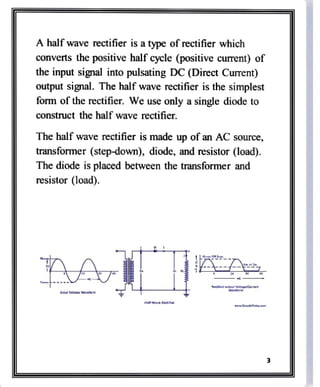
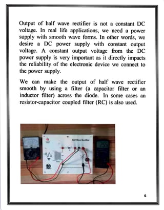
VELS VIDHYASHRAM
SENIOR SECONDARY
SCHOOL
PHYSICS INVESTIGATORY
PROJECTI
MEASURING CURRENT
********
USINGHALFWAVE
RECTIFIER
DONE F
NAME:-MATHESH.T
CLASS:-NI-B
ROLL NO:-12225
Index
SI.No Content Page No
Acknowledgement
Introduction
Theory
Experiment
Observation Table 10
Result 11
Conclusion 12
Bibliography 13
Acknowledgement
I would like to thank the Physics Lab Teacher
Mrs.Nalini mam for giving the extraordinary idea
about this project and guiding this project until
finish line.We would also like to express our thanks
to our Physics Teacher Mrs.Sowmya mam for
getting this idea about this project and encouraging
us.
Our thanks should not stop alone with
teachers.Our friends and parents even played a big
part in it.I see this project as a result of hardwork
from us and innovation from our teacher.So, we
once again thank all of them who put their hands in
it and made successful
INTRODUCTION
A rectifier a simple diode or group of diodes which
converts the Altemating Current (AC) into Direct
Current (DC).
We know that a diode allows electric current in one
direction and blocks electric current in another
direction. We are using this principle to construct
various types of rectifiers.
Rectifiers are classified into different types based on
the number of diodes used in the cireuit or
arrangement of diodes in the circuit. The basic types
of rectifiers are: half wave rectifier and full wave
rectifier.
A half wave rectifier is a type of rectifier which
converts the positive half cycle (positive current) of
the input signal into pulsating DC (Direct Current)
output signal. The half wave rectifier is the simplest
form of the rectifier. We use only a single diode to
construct the half wave rectifier.
The half wave rectifier is made up of an AC source,
transformer (step-dowm), diode, and resistor (load).
The diode is placed between the transformer and
resistor (load).
A
nput vatage Wavuturm
.taTdep cam
THEORYY
The half-wave rectifier circuit is made by using a
semiconductor diode (D) with a load resistance RL
The diode is connected in series with the secondary
of the transformer and the load resistance Ri. The
primary of the transformer is being connected to the
ac supply mains.
The ac voltage across the secondary winding
changes polarities after every half cycle of input
wave. During the positive half-cycles of the input ac
voltage i.e. when upper end of the secondary
winding is positive w.rt. its lower end, the diode is
forward biased and therefore conducts current. f the
forward resistance of the diode is assumed to be zero
(in practice, however, a small resistance exists) the
input voltage during the positive half-cycles is
directly applied to the load resistance RL, making its
upper end positive w.r.t. its lower end. The
waveforms of the output current and output voltage
are of the same shape as that of the input ac voltage.
During the negative half cycles of the input ac
voltage i.e. when the lower end of the secondary
winding is positive w.r.t. its upper end, the diode is
reverse biased and so does not conduct. Thus during
the negative half cycles of the input ac voltage, the
current through and voltage across the load remains
zero. The reverse current, being very small in
magnitude, is neglected. Thus for the negative half
cycles no power is delivered to the load.
Thus the output voltage (VL) developed across load
resistance RL is a series of positive half cycles of
alternating voltage, with intervening very small
constant negative voltage levels, It is obvious from
the figure that the output is not a steady dc, but only
a
pulsating dc wave. To make the output wave
smooth and useful in a DC power supply, we have to
use a filter across the load. Since only half-cycles of
the input wave are used, it is called a half wave
rectifier.
Output of half wave rectifier is not a constant DC
voltage. In real life applications, we need a power
Supply with smooth wave forms. In other words, we
desire a DC power supply with constant output
voltage. A constant output voltage from the DC
power supply is very important as it directly impacts
the reliability of the electronic device we connect to
the power supply.
We can make the output of half wave rectifier
smooth by using a filter (a capacitor filter or an
inductor filter) across the diode. In some cases an
resistor-capacitor coupled filler (RC) is also used.

04 Jan 2023.pdf

  • 1.
    VELS VIDHYASHRAM SENIOR SECONDARY SCHOOL PHYSICSINVESTIGATORY PROJECTI MEASURING CURRENT ******** USINGHALFWAVE RECTIFIER DONE F NAME:-MATHESH.T CLASS:-NI-B ROLL NO:-12225
  • 2.
    Index SI.No Content PageNo Acknowledgement Introduction Theory Experiment Observation Table 10 Result 11 Conclusion 12 Bibliography 13
  • 3.
    Acknowledgement I would liketo thank the Physics Lab Teacher Mrs.Nalini mam for giving the extraordinary idea about this project and guiding this project until finish line.We would also like to express our thanks to our Physics Teacher Mrs.Sowmya mam for getting this idea about this project and encouraging us. Our thanks should not stop alone with teachers.Our friends and parents even played a big part in it.I see this project as a result of hardwork from us and innovation from our teacher.So, we once again thank all of them who put their hands in it and made successful
  • 4.
    INTRODUCTION A rectifier asimple diode or group of diodes which converts the Altemating Current (AC) into Direct Current (DC). We know that a diode allows electric current in one direction and blocks electric current in another direction. We are using this principle to construct various types of rectifiers. Rectifiers are classified into different types based on the number of diodes used in the cireuit or arrangement of diodes in the circuit. The basic types of rectifiers are: half wave rectifier and full wave rectifier.
  • 5.
    A half waverectifier is a type of rectifier which converts the positive half cycle (positive current) of the input signal into pulsating DC (Direct Current) output signal. The half wave rectifier is the simplest form of the rectifier. We use only a single diode to construct the half wave rectifier. The half wave rectifier is made up of an AC source, transformer (step-dowm), diode, and resistor (load). The diode is placed between the transformer and resistor (load). A nput vatage Wavuturm .taTdep cam
  • 6.
    THEORYY The half-wave rectifiercircuit is made by using a semiconductor diode (D) with a load resistance RL The diode is connected in series with the secondary of the transformer and the load resistance Ri. The primary of the transformer is being connected to the ac supply mains. The ac voltage across the secondary winding changes polarities after every half cycle of input wave. During the positive half-cycles of the input ac voltage i.e. when upper end of the secondary winding is positive w.rt. its lower end, the diode is forward biased and therefore conducts current. f the forward resistance of the diode is assumed to be zero (in practice, however, a small resistance exists) the input voltage during the positive half-cycles is directly applied to the load resistance RL, making its upper end positive w.r.t. its lower end. The
  • 7.
    waveforms of theoutput current and output voltage are of the same shape as that of the input ac voltage. During the negative half cycles of the input ac voltage i.e. when the lower end of the secondary winding is positive w.r.t. its upper end, the diode is reverse biased and so does not conduct. Thus during the negative half cycles of the input ac voltage, the current through and voltage across the load remains zero. The reverse current, being very small in magnitude, is neglected. Thus for the negative half cycles no power is delivered to the load. Thus the output voltage (VL) developed across load resistance RL is a series of positive half cycles of alternating voltage, with intervening very small constant negative voltage levels, It is obvious from the figure that the output is not a steady dc, but only a pulsating dc wave. To make the output wave smooth and useful in a DC power supply, we have to use a filter across the load. Since only half-cycles of the input wave are used, it is called a half wave rectifier.
  • 8.
    Output of halfwave rectifier is not a constant DC voltage. In real life applications, we need a power Supply with smooth wave forms. In other words, we desire a DC power supply with constant output voltage. A constant output voltage from the DC power supply is very important as it directly impacts the reliability of the electronic device we connect to the power supply. We can make the output of half wave rectifier smooth by using a filter (a capacitor filter or an inductor filter) across the diode. In some cases an resistor-capacitor coupled filler (RC) is also used.