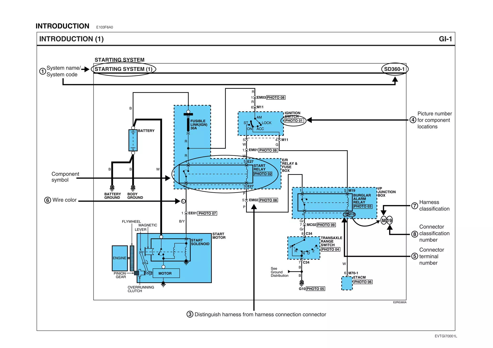
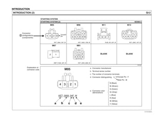
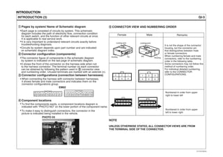
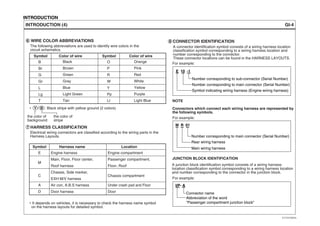
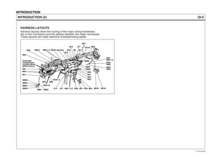
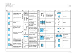
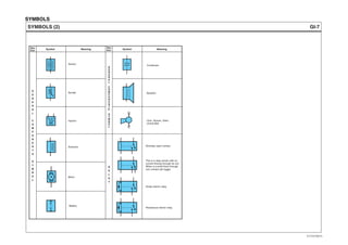
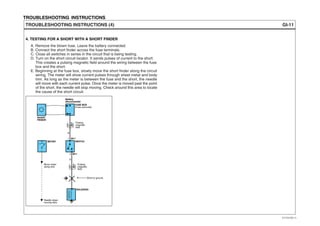
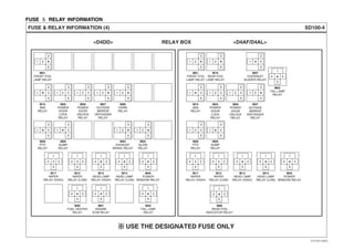
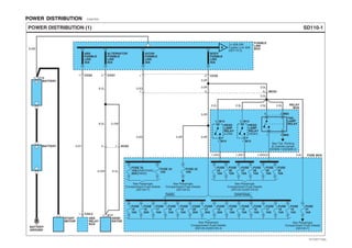
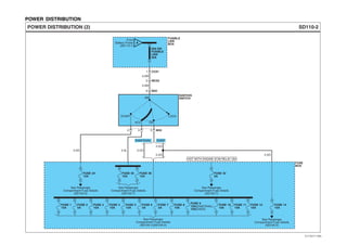
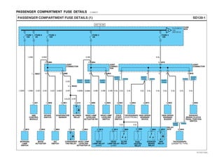
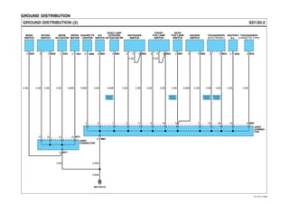
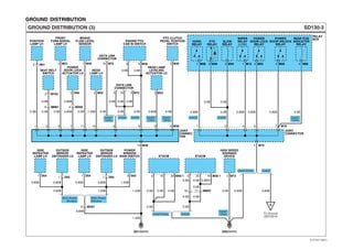
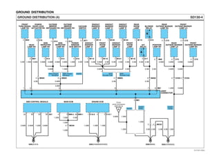
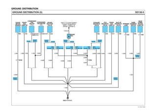
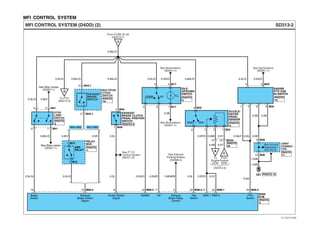
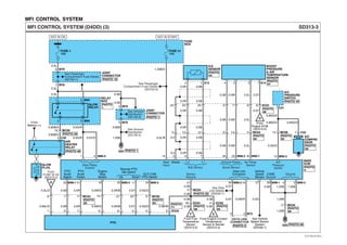
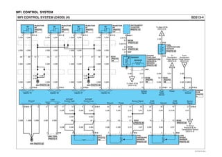
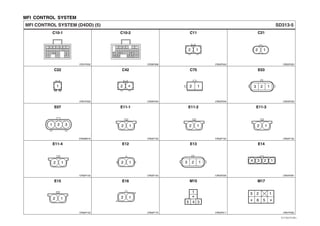
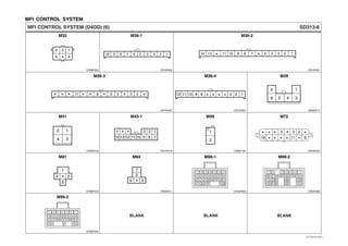
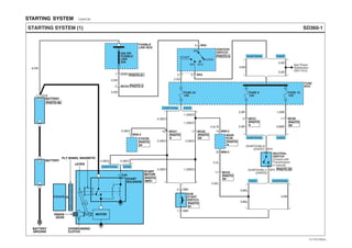
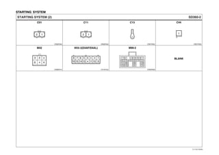
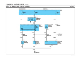
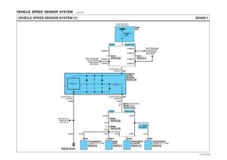
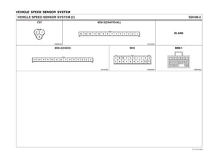
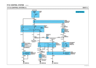
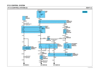
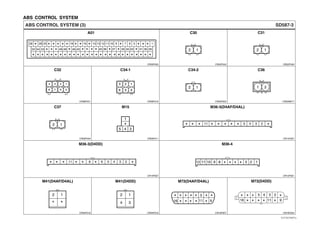
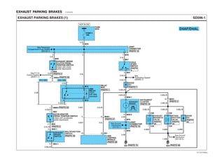
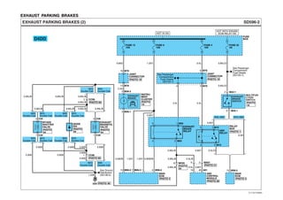
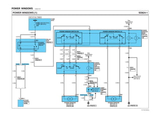
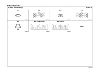
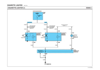
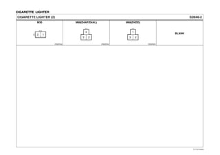
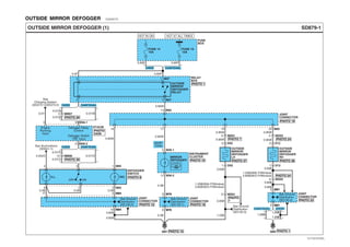
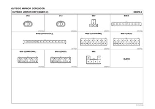
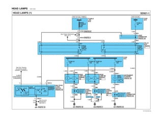
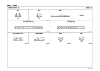
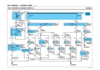
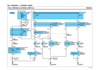
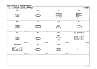
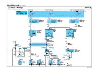
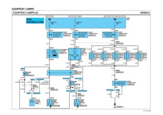
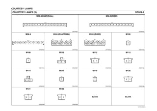
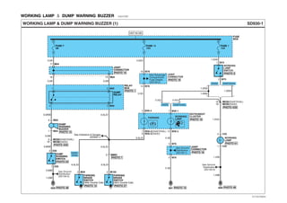
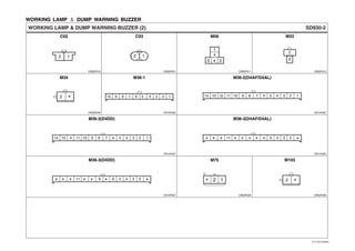
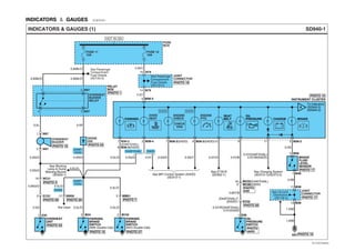
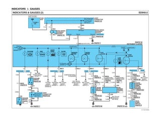
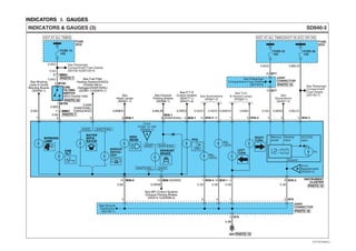
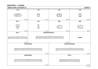
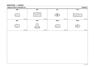
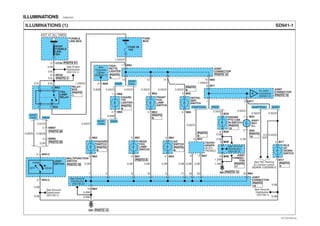
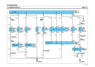
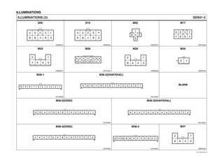
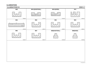
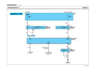
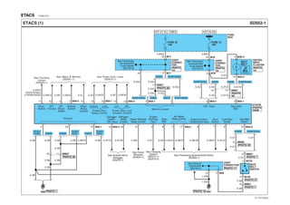
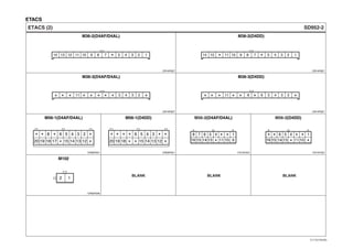
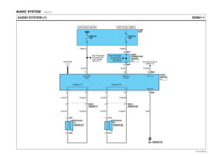
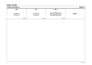
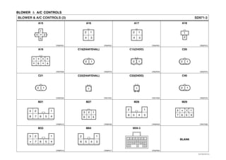
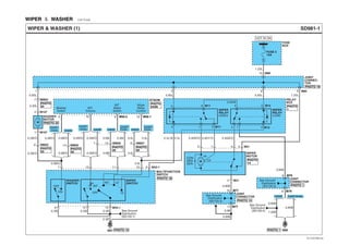
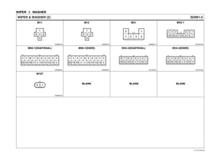
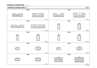
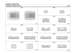
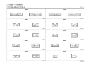
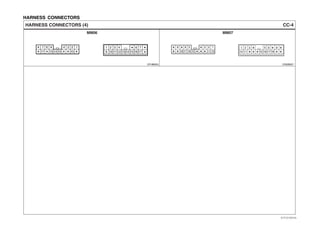
This document provides information and instructions for troubleshooting vehicle electrical systems. It begins with an introduction that defines various symbols used in schematic diagrams, such as wire colors, connectors, components, and general troubleshooting procedures. The introduction also describes how to interpret schematic diagrams and locate components. Schematic diagrams are organized by system and include circuits, connector configurations, and component locations. The document provides symbols for components, grounds, splices, connectors and general electrical symbols. It concludes with instructions for a five-step troubleshooting procedure and notes on using appropriate troubleshooting equipment.
2009 IVECO DAILY 4 Service Repair Manualjknmms ekdms
This is the Highly Detailed factory service repair manual for the2009 IVECO DAILY 4, this Service Manual has detailed illustrations as well as step by step instructions,It is 100 percents complete and intact. they are specifically written for the do-it-yourself-er as well as the experienced mechanic.2009 IVECO DAILY 4 Service Repair Workshop Manual provides step-by-step instructions based on the complete dis-assembly of the machine. It is this level of detail, along with hundreds of photos and illustrations, that guide the reader through each service and repair procedure. Complete download comes in pdf format which can work under all PC based windows operating system and Mac also, All pages are printable. Using this repair manual is an inexpensive way to keep your vehicle working properly.
Service Repair Manual Covers:
General
Engine
Clutch
Transmission
Propeller Shafts
Rear Axles
Axles
Suspensions
Wheel and Tyres
Steering Gear
Hydro Pneumatic System
Brakes
Bodywork
Chassis Frame
Cab
Air Conditioning
Scheduled Maintenance
Electric System
Electronic System
Product Code
File Format: PDF
Compatible: All Versions of Windows & Mac
Language: English
Requirements: Adobe PDF Reader
NO waiting, Buy from responsible seller and get INSTANT DOWNLOAD, Without wasting your hard-owned money on uncertainty or surprise! All pages are is great to have2009 IVECO DAILY 4 Service Repair Workshop Manual.
Looking for some other Service Repair Manual,please check:
https://www.aservicemanualpdf.com/
Thanks for visiting!
8
VOLVO EC460B LC EC460BLC EXCAVATOR Service Repair Manualfujdfjjskrtekme
This is the Highly Detailed factory service repair manual for theVOLVO EC460B LC EC460BLC EXCAVATOR, this Service Manual has detailed illustrations as well as step by step instructions,It is 100 percents complete and intact. they are specifically written for the do-it-yourself-er as well as the experienced mechanic.VOLVO EC460B LC EC460BLC EXCAVATOR Service Repair Workshop Manual provides step-by-step instructions based on the complete dis-assembly of the machine. It is this level of detail, along with hundreds of photos and illustrations, that guide the reader through each service and repair procedure. Complete download comes in pdf format which can work under all PC based windows operating system and Mac also, All pages are printable. Using this repair manual is an inexpensive way to keep your vehicle working properly.
Service Repair Manual Covers:
General
Safety
1 Standard Parts, Service
2 Engine with Mounting and Equipment
3 Elec. System, Warning System, Information System, Instruments
4 Power Transmission
5 Frame and Crawler Unit
6 Machinery House, Cab, Exterior Trim Parts Anywhere
7 Hydraulic System, Digging, Handling, Grading Equipment
File Format: PDF
Compatible: All Versions of Windows & Mac
Language: English
Requirements: Adobe PDF Reader
NO waiting, Buy from responsible seller and get INSTANT DOWNLOAD, Without wasting your hard-owned money on uncertainty or surprise! All pages are is great to haveVOLVO EC460B LC EC460BLC EXCAVATOR Service Repair Workshop Manual.
Looking for some other Service Repair Manual,please check:
https://www.aservicemanualpdf.com/
Thanks for visiting!
This is the Highly Detailed factory service repair manual for theJCB 3.0D 4×4, 3.5D 4×4 TELETRUK, this Service Manual has detailed illustrations as well as step by step instructions,It is 100 percents complete and intact. they are specifically written for the do-it-yourself-er as well as the experienced mechanic.JCB 3.0D 4×4, 3.5D 4×4 TELETRUK Service Repair Workshop Manual provides step-by-step instructions based on the complete dis-assembly of the machine. It is this level of detail, along with hundreds of photos and illustrations, that guide the reader through each service and repair procedure. Complete download comes in pdf format which can work under all PC based windows operating system and Mac also, All pages are printable. Using this repair manual is an inexpensive way to keep your vehicle working properly.
Service Repair Manual Covers:
General Information
Care and Safety
Routine Maintenance
Attachments
Body and Framework
Electrics
Controls
Hydraulics
Transmission
Brakes
Steering
Engine
File Format: PDF
Compatible: All Versions of Windows & Mac
Language: English
Requirements: Adobe PDF Reader
NO waiting, Buy from responsible seller and get INSTANT DOWNLOAD, Without wasting your hard-owned money on uncertainty or surprise! All pages are is great to haveJCB 3.0D 4×4, 3.5D 4×4 TELETRUK Service Repair Workshop Manual.
Looking for some other Service Repair Manual,please check:
https://www.aservicemanualpdf.com/
Thanks for visiting!
JCB 3185 FASTRAC Service Repair Manual SN:00640001-00641999jksmrremmd
This is the Highly Detailed factory service repair manual for theJCB 3185 FASTRAC, this Service Manual has detailed illustrations as well as step by step instructions,It is 100 percents complete and intact. they are specifically written for the do-it-yourself-er as well as the experienced mechanic.JCB 3185 FASTRAC Service Repair Workshop Manual provides step-by-step instructions based on the complete dis-assembly of the machine. It is this level of detail, along with hundreds of photos and illustrations, that guide the reader through each service and repair procedure. Complete download comes in pdf format which can work under all PC based windows operating system and Mac also, All pages are printable. Using this repair manual is an inexpensive way to keep your vehicle working properly.
Service Repair Manual Covers:
General Information
Care and Safety
Routine Maintenance
Optional Equipment
Body and Framework
Electrics
Controls
Hydraulics
Transmission
Brakes
Steering
Suspension
Engine
File Format: PDF
Compatible: All Versions of Windows & Mac
Language: English
Requirements: Adobe PDF Reader
NO waiting, Buy from responsible seller and get INSTANT DOWNLOAD, Without wasting your hard-owned money on uncertainty or surprise! All pages are is great to haveJCB 3185 FASTRAC Service Repair Workshop Manual.
Looking for some other Service Repair Manual,please check:
https://www.aservicemanualpdf.com/
Thanks for visiting!
𝘼𝙣𝙩𝙞𝙦𝙪𝙚 𝙋𝙡𝙖𝙨𝙩𝙞𝙘 𝙏𝙧𝙖𝙙𝙚𝙧𝙨 𝙞𝙨 𝙫𝙚𝙧𝙮 𝙛𝙖𝙢𝙤𝙪𝙨 𝙛𝙤𝙧 𝙢𝙖𝙣𝙪𝙛𝙖𝙘𝙩𝙪𝙧𝙞𝙣𝙜 𝙩𝙝𝙚𝙞𝙧 𝙥𝙧𝙤𝙙𝙪𝙘𝙩𝙨. 𝙒𝙚 𝙝𝙖𝙫𝙚 𝙖𝙡𝙡 𝙩𝙝𝙚 𝙥𝙡𝙖𝙨𝙩𝙞𝙘 𝙜𝙧𝙖𝙣𝙪𝙡𝙚𝙨 𝙪𝙨𝙚𝙙 𝙞𝙣 𝙖𝙪𝙩𝙤𝙢𝙤𝙩𝙞𝙫𝙚 𝙖𝙣𝙙 𝙖𝙪𝙩𝙤 𝙥𝙖𝙧𝙩𝙨 𝙖𝙣𝙙 𝙖𝙡𝙡 𝙩𝙝𝙚 𝙛𝙖𝙢𝙤𝙪𝙨 𝙘𝙤𝙢𝙥𝙖𝙣𝙞𝙚𝙨 𝙗𝙪𝙮 𝙩𝙝𝙚 𝙜𝙧𝙖𝙣𝙪𝙡𝙚𝙨 𝙛𝙧𝙤𝙢 𝙪𝙨.
Over the 10 years, we have gained a strong foothold in the market due to our range's high quality, competitive prices, and time-lined delivery schedules.
What Could Cause The Headlights On Your Porsche 911 To Stop WorkingLancer Service
Discover why your Porsche 911 headlights might flicker out unexpectedly. From aging bulbs to electrical gremlins and moisture mishaps, we're delving into the reasons behind the blackout. Stay tuned to illuminate the road ahead and ensure your lights shine bright for safer journeys.
The Octavia range embodies the design trend of the Škoda brand: a fusion of
aesthetics, safety and practicality. Whether you see the car as a whole or step
closer and explore its unique features, the Octavia range radiates with the
harmony of functionality and emotion
Comprehensive program for Agricultural Finance, the Automotive Sector, and Empowerment . We will define the full scope and provide a detailed two-week plan for identifying strategic partners in each area within Limpopo, including target areas.:
1. Agricultural : Supporting Primary and Secondary Agriculture
• Scope: Provide support solutions to enhance agricultural productivity and sustainability.
• Target Areas: Polokwane, Tzaneen, Thohoyandou, Makhado, and Giyani.
2. Automotive Sector: Partnerships with Mechanics and Panel Beater Shops
• Scope: Develop collaborations with automotive service providers to improve service quality and business operations.
• Target Areas: Polokwane, Lephalale, Mokopane, Phalaborwa, and Bela-Bela.
3. Empowerment : Focusing on Women Empowerment
• Scope: Provide business support support and training to women-owned businesses, promoting economic inclusion.
• Target Areas: Polokwane, Thohoyandou, Musina, Burgersfort, and Louis Trichardt.
We will also prioritize Industrial Economic Zone areas and their priorities.
Sign up on https://profilesmes.online/welcome/
To be eligible:
1. You must have a registered business and operate in Limpopo
2. Generate revenue
3. Sectors : Agriculture ( primary and secondary) and Automative
Women and Youth are encouraged to apply even if you don't fall in those sectors.
How To Fix The Key Not Detected Issue In Mercedes CarsIntegrity Motorcar
Experiencing a "Key Not Detected" problem in your Mercedes? Don’t take it for granted. Go through this presentation to find out the exact nature of the issue you are dealing with. Have your vehicle checked by a certified professional if necessary.
Ever been troubled by the blinking sign and didn’t know what to do?
Here’s a handy guide to dashboard symbols so that you’ll never be confused again!
Save them for later and save the trouble!
What Are The Immediate Steps To Take When The VW Temperature Light Starts Fla...Import Motorworks
Learn how to respond when the red temperature light flashes in your VW with this presentation. From checking coolant levels to seeking professional help, follow these steps promptly to prevent engine damage and ensure safety on the road.
Your VW's camshaft position sensor is crucial for engine performance. Signs of failure include engine misfires, difficulty starting, stalling at low speeds, reduced fuel efficiency, and the check engine light. Prompt inspection and replacement can prevent further damage and keep your VW running smoothly.
Learn why monitoring your Mercedes' Exhaust Back Pressure (EBP) sensor is crucial. Understand its role in engine performance and emission reduction. Discover five warning signs of EBP sensor failure, from loss of power to increased emissions. Take action promptly to avoid costly repairs and maintain your Mercedes' reliability and efficiency.
Fleet management these days is next to impossible without connected vehicle solutions. Why? Well, fleet trackers and accompanying connected vehicle management solutions tend to offer quite a few hard-to-ignore benefits to fleet managers and businesses alike. Let’s check them out!
Things to remember while upgrading the brakes of your carjennifermiller8137
Upgrading the brakes of your car? Keep these things in mind before doing so. Additionally, start using an OBD 2 GPS tracker so that you never miss a vehicle maintenance appointment. On top of this, a car GPS tracker will also let you master good driving habits that will let you increase the operational life of your car’s brakes.
Things to remember while upgrading the brakes of your car
HD78 электросхема
1. INTRODUCTION E103F6A0
GI-1INTRODUCTION (1)
STARTING SYSTEM (1)
STARTING SYSTEM
System name/
System code
Component
symbol
Wire color
SD360-1
E2RG360A
START
SOLENOID
START
MOTOR
BATTERY
BATTERY
GROUND
BODY
GROUND
MOTOR
ENGINE
LEVER
MAGNETIC
OVERRUNNING
CLUTCH
PINION
GEAR
FLYWHEEL
WBB
P
R
N D
L
2
TRANSAXLE
RANGE
SWITCH
ETACM
IGNITION
SWITCH
ON
ST
ACC
LOCK
AM
6
R
R
M11
M11
E27
E27
8 C34
7 C34
5
2 3
M19
M19
3
M70-16
M1951
4
51
START
RELAY
E/R
RELAY &
FUSE
BOX
BURGLAR
ALARM
RELAY
I/P
JUNCTION
BOX
4
FUSIBLE
LINK(IGN)
30A
1 EE01
L
B
G10
1 EM01
1 EM03 PHOTO 08
PHOTO 01
PHOTO 08
PHOTO 08
PHOTO 09
PHOTO 04
PHOTO 06
PHOTO 07
PHOTO 05
PHOTO 03
PHOTO 02
W
W
G
R
R
EM025
MC027
P
P
W
Gr
Gr
B
B
B/Y
See
Ground
Distribution
Distinguish harness from harness connection connector3
Picture number
for component
locations
4
1
Harness
classification
7
Connector
classification
number
Connector
terminal
number
8
5
6
EVTGI70001L
2. INTRODUCTION
GI-2INTRODUCTION (2)
Connector
configurations
(components)
Explanation of
connector code
2
M05 a : Connector manufacturer
b : Terminal series number
c : The number of connector terminals
d : Connector distinguishing
e : Connector color
abbreviations
KET_090II_04F_W
1
a b c d e
234
B (Black)
Br (Brown)
G (Green)
Gr (Gray)
L (Blue)
R (Red)
W (White)
Y (Yellow)
Female Pin : F
Male Pin : M
M05
KET_090II_04F_W KET_090II_10M_W
AMP_PLM2_02F_B KET_090II_06M_W
KUM_AR_04F_W KET_090II_10F_W
M06 M11 M13
BLANK BLANK
M81M67
*234
1 2
*
*
4
5 6 8 9 10 1234
134
5678
12 1 2
3 4 5 6
Unused
pin
*
**
STARTING SYSTEM (2)
STARTING SYSTEM
SD360-2
E2RG360B
EVTGI70002L
3. INTRODUCTION
GI-3INTRODUCTION (3)
Pages by system/ Name of Schematic diagram
Each page is consisted of circuits by system. This schematic
diagram includes the path of electricity flow, connection condition
for each switch, and the function of other relevant circuits at once.
It is applicable to real service work.
1
Connector configurations (connection between harnesses)
The connector figure of components in the schematic diagram
by system is indicated on the last page of schematic diagram.
It shows the front of the connector on the harness side when not
to the harness connector. The terminal number on each connector
can be obtained by following the pattern used in 5 connector view
and numbering order. Unused terminals are marked with an asterisk ( ).
When connecting the harness with connector between harnesses,
it shows female and male connectors and indicates them on the
connector configurations group.
To find the components easily, a component locations diagram is
indicated with "PHOTO NO" on the lower portion of the component name.
To make it easy to distinguish connectors, the connector in the
picture is indicated being installed in the vehicle.
Circuits by system depends upon part number and are indicated
on schematic diagram index.
10 9 8 7 6 5 4 3
2122
12
17181920 16 15 1314 12 11
109876543
21 22
1 2
17 18 19 20161513 141211
EM02
PHOTO 03
3 2 1
6 5 4
1 2 3
4 5 6
3 2 1
6 5 4
1 2 3
4 5 6
Connector configuration (components)2
3
Component locations4
CONNECTOR VIEW AND NUMBERING ORDER5
It is very important to understand relevant circuits exactly before
troubleshooting diagnosis.
Male
It is not the shape of the connector
housing, but the connector pin
that distinguishes between male
or female connectors.
When numbering female and male
connectors, refer to the numbering
order in the following table.
Some connectors may not follow this
method of numbering order.
For individual detailed numbering,
refer to the CONNECTOR
CONFIGURATIONS.
Female Remarks
Locking point
Housing Pin
Locking point
Pin
Housing
Numbered in order from upper
right to lower left
Numbered in order from upper
left to lower right
NOTE
UNLESS OTHERWISE STATED, ALL CONNECTOR VIEWS ARE FROM
THE TERMINAL SIDE OF THE CONNECTOR.
*
EVTGI70003L
4. INTRODUCTION
GI-4INTRODUCTION (4)
WIRE COLOR ABBREVIATIONS
The following abbreviations are used to identify wire colors in the
circuit schematics.
6
A connector identification symbol consists of a wiring harness location
classification symbol corresponding to a wiring harness location and
number corresponding to the connector.
These connector locations can be found in the HARNESS LAYOUTS.
HARNESS CLASSIFICATION
Electrical wiring connectors are classified according to the wiring parts in the
Harness Layouts.
7
CONNECTOR IDENTIFICATION8
It depends on vehicles, it is necessary to check the harness name symbol
on the harness layouts for detailed symbol.
Black
Brown
Green
Gray
Blue
Light Green
Tan
Orange
Pink
Red
White
Yellow
Purple
Light Blue
the color of
background
the color of
stripe
For example:
For example:
For example:
O
P
R
W
Y
Pp
LI
B
Br
G
Gr
L
Lg
T
Symbol Color of wire Symbol Color of wire
E 10 -1
NOTE
Connectors which connect each wiring harness are represented by
the following symbols.
JUNCTION BLOCK IDENTIFICATION
A junction block identification symbol consists of a wiring harness
location classification symbol corresponding to a wiring harness location
and number corresponding to the connector in the junction block.
M R 01
I/P- A
Symbol indicating wiring harness (Engine wiring harness)
Number corresponding to main connector (Serial Number)
Number corresponding to sub-connector (Serial Number)
Number corresponding to main connector (Serial Number)
Rear wiring harness
Main wiring harness
Abbreviation of the word
"Passenger compartment junction block"
Connector name
Y / B : Black stripe with yellow ground (2 colors)*
Engine harness
Main, Floor, Floor center,
Roof harness
Chassis, Side marker,
EXH M/V harness
Air con, A.B.S harness
Door harness
E
A
D
LocationHarness nameSymbol
C
M
Engine compartment
Passenger compartment,
Floor, Roof
Under crash pad and Floor
Door
Chassis compartment
EVTGI70004L
5. INTRODUCTION
GI-5INTRODUCTION (5)
HARNESS LAYOUTS
Harness layouts show the routing of the major wiring harnesses,
the in-line connectors and the splices between the major harnesses.
These layouts will make electrical troubleshooting easier.
MM02 G14 G12 M26 M31 M34 M35
M32
M22
M21
M23
M25-1,2,3
MM01
MM03
M33
SM01 SM02
M36
MM04
M41
VIEW 'B'
VIEW 'A'
M30
Z03M29 M15
M13 M19-2
SM06
SM08
SM07
M37
M02
M03-1,2
MI04
MI06
MI03
MI05
M20
M11M16 Z01
G11
M14
MC06
MC05 MC04
M09-3 M09-1,2
MI01
Z02
Passenger
Compartment
Junction Block
(I/P-E,F,G,H,J)
EVTGI70005L
6. SYMBOLS EBB531CD
GI-6SYMBOLS (1)
C
O
M
P
O
N
E
N
T
G
R
O
U
N
D
S
P
L
I
C
E
S
C
O
N
N
E
C
T
O
R
W
I
R
E
Symbol
Sec-
tion
Sec-
tion
Sec-
tion
Sec-
tion
A solid line means the entire
component is shown.
Shows the name of each connector
on the component location index
for reference.
Indicates the number of
corresponding terminal.
(Only relevant terminal on the
corresponding schematic diagram).
The dashed-line means each of
two wires connect with same
connector(E35)
A broken line indicates only
part of the component is
shown.
Meaning Symbol Meaning Symbol Meaning Symbol Meaning
STOP
LAMP
SWITCH
PHOTO 03
Female
connector
Male
connector
10 M05-2
E35
R Y/L
R Y/L
13
B
A
R
Y/R
A
From C52
To MC02
G
G G
L
L
D
I
O
D
E
TR
C
B
E
F
U
S
E
G
E
N
E
R
A
L
C
O
M
P
O
N
E
N
T
S
Y
M
B
O
L
L
A
M
P
Diode
Led diode
Zener diode
Switch (1 contact point)
Heater
NPN
PNP
NPN
PNP
Power supplied at all times.
Control battery power at all times
Double filament
Single filament
Name
Capacity
HOT IN ON
FUSE 10
10A
DASH
FUSE
BOX
C
B
E
S
H
I
E
L
D
W
I
R
E
J
O
I
N
T
C
O
N
N
E
C
T
O
R
S
L
O
W
B
L
O
W
P
O
W
E
R
G06
This means the connector
connects directly to the
component.
This indicates a screw terminal
on the component.
This means power is supplied
with the ignition on position.
Identification
Current rating
This means the short bar
connects to other fuses.
This indicates the connector
connects to a lead (pigtail),
wired directly to the com-
ponent.
Automatic
Transaxle
Manual
Transaxle
This symbol means the end
of the wire is attached to a
metal part of the vehicle.
This ground symbol (dot and
3 lines overlapping the com-
ponent) means the housing
of the component is attached
to a metal part of the vehicle.
The name of the component
appears next to its upper right
corner.
Shows the number of pictures
for component location.
Splices are numbered and
shown as a dot with circle.
The exact location and con-
nection of these splices may
vary among vehicles.
Wire choices for options or
different models are labeled
and shown with a "choice"
bracket like this.
Name of Circuit
A wire connects to another
circuit. The wire is shown
again on that circuit which
the arrow is pointing.
Current path is continued on
the same page or another
page.The arrow shows the
direction of current flow.
You should look for the "A"
in the marked position.
A wavy line means the
wire is broken but
is to be continued.
Wire insulation is yellow
with a red strip.
C
O
N
N
E
C
T
O
R
This represents RFI (Radio
Frequency Interference)
Shielding around a wire.
The shielding is always
connected to ground.
This is a connector showing
the joining wires.
These switches move
together:
a dashed line shows a
mechanical connection
between them.
F/FOG
FUSE
15A
E/R FUSE &
RELAY
BOX
HOT AT ALL TIMES
G06
EVTGI70006L
8. TROUBLESHOOTING INSTRUCTIONS E69D8CAB
GI-8TROUBLESHOOTING INSTRUCTIONS (1)
TROUBLESHOOTING INSTRUCTIONS
TROUBLESHOOTING PROCEDURES TROUBLESHOOTING EQUIPMENT
CAUTION
The following five-step troubleshooting procedure is recommended.
Turn on all the components in the problem circuit to check the accuracy of the
customer's complaints. Note the symptoms.
Do not begin disassembly or testing until you have narrowed down the probable
causes.
1. Verify the customer's complaints Use a test lamp or a voltmeter on circuits without solidstate units and use a test
lamp to check for voltage. A test lamp is made up of a 12-volt light bulb with a
pair of leads attached. After grounding one lead, touch the other lead to various
points along the circuit where voltage should be present.
When the bulb goes on, there is voltage at the point being tested.
SELF-POWERED TEST LAMP AND OHMMETER
Use a self-powered test lamp or an ohmmeter to check for continuity.
The ohmmeter shows how much resistance there is between two points along
a circuit. Low resistance means good continuity.
A number of circuits include solid-state modules, such as the Engine
Control Module(ECM), used with computer command control injection.
Voltage in these circuits should be tested only with a 10-megaohm or
higher impedance digital multimeter. Never use a test lamp on circuits
that contain solid state modules. Damage to the modules may result.
VOLTMETER AND TEST LAMP
Make a circuit test to check the diagnosis you made in step 2. Remember that a
logical, simple procedure is the key to efficient troubleshooting. Narrow down the
probable causes using the troubleshooting hints and system diagnosis charts.
Test for the most likely cause of failure first.
Try to make tests at points that are easily accessible.
3. Inspect the circuit/ component with the problem isolated
Once the problem is found, make the necessary repairs.
4. Repair the problem
Repeat the system check to be sure you have repaired the problem. If the
problem was a blown fuse, be sure to test all of the circuits on that fuse.
5. Make sure the circuit works
Locate the schematic for the problem circuit. Determine how the circuit is
supposed to work by tracing the current paths from the power source through
the system components to ground. If you do not understand how the circuit
should work, read the circuit operation text. Also check other circuits that share
with the problem circuit. The name of circuits that share the same fuse, ground,
or switch, for example, are referred to on each diagram. Try to operate any
shared circuits you did not check in step 1. If the shared circuit works, the
shared wiring is okay, and the cause must be within the wiring used only by the
problem circuit.
If several circuits fail at the same time, the fuse or ground is a likely cause.
2. Read and analyze the schematic diagram
TEST LAMP
A voltmeter can be used in place of a test lamp. While a test lamp shows
whether the voltage is present or not, a voltmeter indicates how much voltage
is present.
EVTGI70008L
9. TROUBLESHOOTING INSTRUCTIONS
GI-9TROUBLESHOOTING INSTRUCTIONS (2)
Never use a self-powered test lamp on circuits that contain solid state
modules. Damage to these modules may result.
An ohmmeter can be used in place of a self-powered test lamp.
The ohmmeter shows how much resistance there is between two points along a
circuit. Low resistance means good continuity.
Circuits which include any solid-state devices should be tested only with a
10-megaohm or higher impedance digital multimeter. When measuring
resistance with a digital multimeter, the battery negative terminal should be
disconnected. Otherwise, there may be incorrect readings. Diodes and
solid-state devices in a circuit can make an ohmmeter give a false reading.
To find out if a component is affecting a measurement, take one reading,
reverse the leads and take a second reading.
If different the solid-state device is affecting the measurement.
Use a jumper wire with a fuse to by-pass an open circuit.
A jumper wire is made up of an in-line fuse holder connected to a set of test leads.
This tool is available with small clamp connectors providing adaption to most con-
nectors without damage.
CAUTION
Do not use a fuse with a higher rating than the specified fuse that protects the
circuit being tested. Do not use this tool in any situation to substitute an input
or output at the solid-state control module, such as ECM, TCM, etc.
CAUTION
JUMPER WIRE WITH FUSE
A short finder is available to locate a short to ground. The short finder creates a
pulsing magnetic field in the shorted circuit and shows you the location of the
short through body trim or sheet metal.
SHORT FINDER
SELF-
POWERED
TEST LAMP
5A
TROUBLESHOOTING TEST
This test measures voltage in a circuit. When testing for voltage at a con-
nector, you do not have to separate the two halves of the connector. lnstead,
probe the connector from the back(backprobe). Always check both sides of
the connector because dirt and corrosion between its contact surfaces can
cause electrical problems.
A. Connect one lead of a test lamp or voltmeter to a ground. If you are using
a voltmeter, be sure it is the voltmeter's negative test lead you have con-
nected to ground.
B. Connect the other lead of the test lamp or voltmeter to a selected test
point(connector or terminal).
C. If the test lamp glows, there is voltage present. If you are using a
voltmeter, note the voltage reading. A loss of more than 1 volt from
specification indicates a problem.
1. TESTING FOR VOLTAGE
EVTGI70009L
10. TROUBLESHOOTING INSTRUCTIONS
GI-10TROUBLESHOOTING INSTRUCTIONS (3)
A. Disconnect the battery negative terminal.
B. Connect one lead of a self-powered test lamp or ohmmeter to one end of
the part of the circuit you wish to test. If you are using an ohmmeter, hold
the leads together and adjust the ohmmeter to read zero ohms.
C. Connect the other lead to the other end.
D. If the self-power test lamp glows, there is continuity. If you are using an
ohmmeter, low or zero resistance means good continuity.
2. TESTING FOR CONTINUITY
A. Disconnect the battery negative terminal.
B. Connect one lead of a self-powered test lamp or an ohmmeter to the fuse
terminal on the load side.
C. Connect the other lead to a ground.
D. Beginning near the fuse block move the harness from side to side.
Continue this proceedure(about six inches apart) while watching the
self-powered test lamp or ohmmeter.
E. When the self-powered test lamp glows, or ohmmeter registers, there is a
short to a ground in the wiring near that point.
3. TESTING FOR SHORT TO GROUNDHOT AT ALL TIMES
DASH
FUSE
BOX
SWITCH
SOLENOID
TEST LAMP
OR
VOLTMETER
RON
OFF
G
4 M11
SELF-
POWERED
TEST LAMP
OR
OHMMETER
STOP
LAMP
SWITCH
SOLENOID
G
SELF-POWERED
TEST LAMP
OR
VOLTMETER
Short to ground
Battery
disconnected
FUSE BOX
(Fuse removed)
Load
disconnected
SWITCH
4 M11
1 M11
R
EVTGI70010L
11. TROUBLESHOOTING INSTRUCTIONS
GI-11TROUBLESHOOTING INSTRUCTIONS (4)
A. Remove the blown fuse. Leave the battery connected.
B. Connect the short finder across the fuse terminals.
C. Close all switches in series in the circuit that is being testing.
D. Turn on the short circuit locator. It sends pulses of current to the short.
This creates a pulsing magnetic field around the wiring between the fuse
box and the short.
E. Beginning at the fuse box, slowly move the short finder along the circuit
wiring. The meter will show current pulses through sheet metal and body
trim. As long as the meter is between the fuse and the short, the needle
will move with each current pulse. Once the meter is moved past the point
of the short, the needle will stop moving. Check around this area to locate
the cause of the short circuit.
4. TESTING FOR A SHORT WITH A SHORT FINDER
SHORT
FINDER
FUSE BOX
(Fuse removed)
R
4 M11
SWITCH
SOLENOID
G
Short to ground
Battery
disconnected
M111
METER
Move meter
along wire
Needle stops
moving here
Pulsing
magnetic
field
Pulsing
magnetic
field
EVTGI70011L
64. POWER WINDOWS EB8321D0
SD824-1POWER WINDOWS (1)
PHOTO 1 PHOTO 15
PHOTO 24
PHOTO 38 PHOTO 37
1
8 MD01
MD016
0.85B
0.85B
1.25B
1.25B
0.85R/O
4 9 3 D05
51
0.85Y 0.85R/O 0.85G
0.85Y 0.85G
7 MD01
1.25R
1.25R
POWER
WINDOW
RELAY
2 M04
13 M56-1
0.5Y/O
ETACM
1 M04
1.25B
1.25B
0.85B
5
4
RELAY
BOX
1.25B
1.25Y/O
1.25Y/O
5 6
G02 G01
M813
MD036
M81
JOINT
CONNEC-
TOR
5
PHOTO 1
PHOTO 7
PHOTO 7
PHOTO
24
PHOTO
23
PHOTO
24/26
PHOTO
7
PHOTO
39
PHOTO 20
POWER
WINDOW
MAIN
SWITCH
See Ground
Distribution
(SD130-3)
See Ground
Distribution
(SD130-4)
1.25B
1.25B
1.25B
D4DDD4AF/D4AL
D4DD D4AF/D4AL
0.5Br
0.5Br
0.5Br
MM076
HOT AT ALL TIMES
FUSE
BOX
FUSE 13(D4AF/D4AL)
FUSE 16(D4DD)
20A
M
PHOTO
40
POWER
WINDOW
SUB
SWITCH
POWER WINDOW
MOTOR RH
0.85L
DOWN
OFF
UPDOWN ILL.
OFF
UP
0.85G
0.85Y 0.5G/O0.85G1.25R
6
9 D15
871 MD03
21 D11
24
D155
See
Illuminations
(SD941-2)
8
3
M
POWER WINDOW
MOTOR LH
0.85L 0.85G
21 D01
POWER WINDOW SWITCH RH
DOWN
OFF
UPDOWN
OFF
UP
POWER WINDOW SWITCH LH
DOWN
OFF
UPDOWN
OFF
UP ILL.
0.5G/O
D05
See
Illuminations
(SD941-2)
82
ILL.
EVTSD7824AL