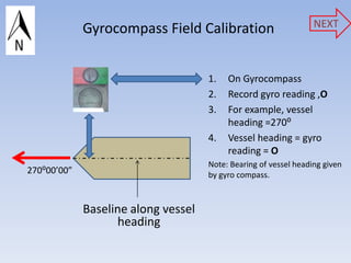
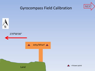
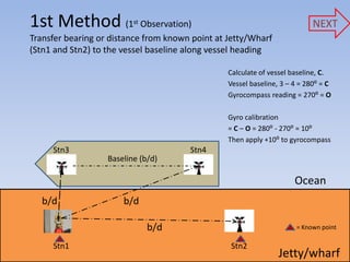
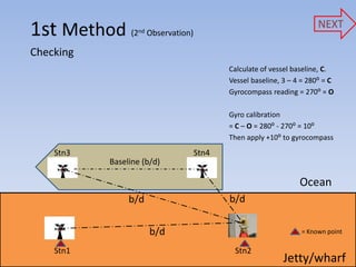
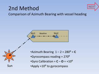
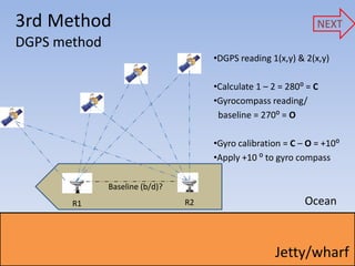
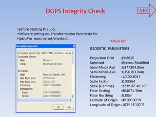
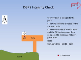
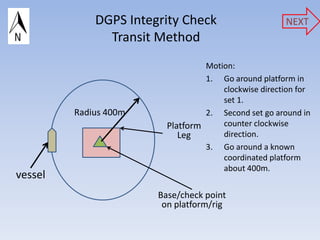
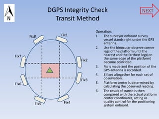
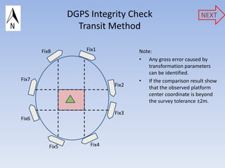
Gyrocompass field calibration edited (download to see full features)
1. NEXT
GYROCOMPASS CALIBRATION
AND
DGPS INTEGRITY CHECK
AP220 –SUG571
OCEANOGRAPHY & OFFSHORE SURVEYING
MOHD NOR BASYAR BIN SAAD 2009736911
BANTIN ANAK IBIK 2009339845
MOHAMAD KHAIRI BIN MOHD GHAZALI 2009668914
START
MARA TECHNOLOGY UNIVERSITY, UiTM
SHAH ALAM, MALAYSIA
4. Gyrocompass Field Calibration NEXT
1. On Gyrocompass
2. Record gyro reading ,O
3. For example, vessel
heading =270⁰
4. Vessel heading = gyro
reading = O
Note: Bearing of vessel heading given
270⁰00’00” by gyro compass.
Baseline along vessel
heading
5. NEXT
Gyrocompass Field Calibration
270⁰00’00”
Jetty/Wharf
= Known point
Land
6. 1st Method (1 stObservation) NEXT
Transfer bearing or distance from known point at Jetty/Wharf
(Stn1 and Stn2) to the vessel baseline along vessel heading
Calculate of vessel baseline, C.
Vessel baseline, 3 – 4 = 280⁰ = C
Gyrocompass reading = 270⁰ = O
Gyro calibration
= C – O = 280⁰ - 270⁰ = 10⁰
Then apply +10⁰ to gyrocompass
Stn3 Stn4
Baseline (b/d)
Ocean
b/d b/d
b/d = Known point
Stn1 Stn2
Jetty/wharf
7. NEXT
1st Method (2nd Observation)
Checking
Calculate of vessel baseline, C.
Vessel baseline, 3 – 4 = 280⁰ = C
Gyrocompass reading = 270⁰ = O
Gyro calibration
= C – O = 280⁰ - 270⁰ = 10⁰
Then apply +10⁰ to gyrocompass
Stn3 Stn4
Baseline (b/d)
Ocean
b/d b/d
b/d = Known point
Stn1 Stn2
Jetty/wharf
8. NEXT
2nd Method
Comparison of Azimuth Bearing with vessel heading
Stn1 Baseline Stn2
•Azimuth Bearing 1 – 2 = 280⁰ = C
•Gyrocompass reading = 270⁰
•Gyro Calibration = C – O = +10⁰
Sun •Apply +10⁰ to gyrocompass
9. 3rd Method NEXT
DGPS method
•DGPS reading 1(x,y) & 2(x,y)
•Calculate 1 – 2 = 280⁰ = C
•Gyrocompass reading/
baseline = 270⁰ = O
•Gyro calibration = C – O = +10⁰
•Apply +10 ⁰ to gyro compass
Baseline (b/d)?
R1 R2 Ocean
Jetty/wharf
10. DGPS Integrity Check NEXT
•Before Starting the Job..
•Software setting ex. Transformation Parameter for
HydroPro must be set/checked..
•Check list
GEODETIC PARAMETERS
Projection Grid :(MRSO)
Spheroid :Everest Modified
Semi Major Axis :6377304.06m
Semi Minor Axis :6356103.04m
Flattening :1/300.8017
Scale Factor :0.99984
Skew (Gamma) :323º 07’ 48.36’’
False Easting :804671.30m
False Northing :0.00m
Latitude of Origin :4º 00’ 00’’N
Longitude of Origin :102º 15’ 00’’E
11. NEXT
DGPS Integrity Check
Survey boat is along side the
jetty.
The GPS antenna is closed to the
a known point.
The coordinates of known point
R1 and the GPS antenna are then
compared to check against any
Stn1 Jetty gross error.
Note:
Compare ( R1 – Stn1) < ±2m
= Known point
Land
12. DGPS Integrity Check NEXT
Transit Method
Motion:
1. Go around platform in
clockwise direction for
set 1.
Radius 400m 2. Second set go around in
Platform counter clockwise
Leg direction.
3. Go around a known
coordinated platform
about 400m.
vessel
Base/check point
on platform/rig
13. DGPS Integrity Check NEXT
Transit Method
Operation:
Fix8 Fix1 1. The surveyor onboard survey
vessel stands right under the GPS
antenna.
2. Use the binocular observe corner
legs of the platform until the
Fix7 nearest and the farthest legs(on
Fix2 the same edge of the platform)
become coincided.
3. Fix is made and the position of the
GPS antenna is recorded.
4. 8 fixes altogether for each set of
Fix3 observation.
Fix6 5. Platform center is determined by
calculating the observed reading.
6. The result of transit is then
compared with the actual platform
center coordinates, acting as
Fix4 quality control for the positioning
Fix5 system onboard.
14. DGPS Integrity Check NEXT
Transit Method
Fix8 Fix1 Note:
• Any gross error caused by
transformation parameters
can be identified.
Fix7 • If the comparison result show
Fix2 that the observed platform
center coordinate is beyond
the survey tolerance ±2m.
Fix3
Fix6
Fix5 Fix4