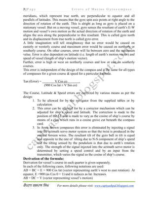
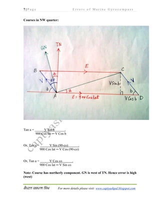
SlideShare a Scribd company logo
1 | P a g e E r r o r s o f M a r i n e G y r o c o m p a s s
For more details please visit: www.captyashpal.blogspot.com
OPERATIONAL ERRORS OF THE GYRO:
1. Latitude error (Damping Error or Settling Error)
2. Course, Latitude & Speed Error (Steaming Error)
3. Ballistic Deflection
4. Ballistic Tilt
5. Rolling Error
6. Inter cardinal Rolling Error
Latitude Error (Damping Error or Settling Error):
This error is due to the eccentricity of the damping weight (i.e. offset of the
mercury ballistic cone bearing).
The spin axis reaches equilibrium and settles in a position at which drifting is
counteracted by control precession & the damping precession counteracts tilting.
Since for any latitude except the equator there will always be a drifting given by
15o
Sin (Lat) per hour. This Dg is counteracted by control precession (Pc) which
comes into action only with tilt. In a given proportion damping precession (Pd)
also accompanies, which counteracts the tilting (Tg). This results in tilt being
reduced which in turn will reduce the Pc. This means that some sustained increase
in Tg is required which compensates for this. But Tg can occur only when spin
axis is off the meridian, as Tg at meridian is nil.
2 | P a g e E r r o r s o f M a r i n e G y r o c o m p a s s
For more details please visit: www.captyashpal.blogspot.com
Therefore the spin axis of the gyro settles off the meridian & slightly tilted, where
all the forces balance out. That is Dg = Pc and Tg = Pd
In N lat this position is slightly above the horizon and east of the meridian and in S
lat the spin axis settles slightly below the horizon and west of meridian.
This error can be calculated for given latitude and applied manually. In Sperry
compass this error is allowed for by moving lubber line by means of auxiliary
latitude corrector. Tilt is very slight and can be ignored.
This error occurs only in gyro compasses damped in tilt and not in compasses
damped in azimuth
Formula for Latitude error:
At the settling position:
Drifting (Dg) = Control precession (Pc)
Tilting (Tg) = Damping precession (Pd)
Or, 15 Sin lat = Pc and, ---------------- (1)
15 Cos lat. Sin Az. = Pd -------------- (2)
Dividing (2) by (1), we have:
Cos lat. Sin Az = Pd = Pc (In Sperry compass, Pd = Pc/40)
Sin lat Pc 40 Pc
Or, Sin Az = K Tan lat (Where, K = 1/40, in Sperry compass)
Thus: Sin Az = Tan lat/40 (in Sperry compass eccentricity = 1/40)
Since azimuth is very small, we have: Az (radians) = Tan lat/40
Or, Az (degrees) = 57.3 Tan lat/40 = 1.43 Tan lat
Thus Azimuth (DE or SE or LE in degrees) = K Tan Lat (where K=constant, about
1.43 in Sperry Compass)
Thus students can use either of the two formulas:
1. Sin Az = 1/40.Tan lat.
2. Az in degrees = 1.43 Tan lat.
Where Az is Damping error (or Settling error or Latitude error)
Course & Speed error (Steaming error):
Gyrocompass is basically a fast spinning gyrosphere which is controlled and
damped so as to make it point and keep pointing true north. We know that all
3 | P a g e E r r o r s o f M a r i n e G y r o c o m p a s s
For more details please visit: www.captyashpal.blogspot.com
meridians, which represent true north, are perpendicular to equator and all
parallels of latitudes. This means that the gyro spin axis points at right angle to the
direction of rotation of the earth. This is alright as long as gyro is placed on a
stationary vessel. But on a moving vessel, gyro senses the resultant of earth’s E-W
motion and vessel’s own motion as the actual direction of rotation of the earth and
aligns the axis along the perpendicular to this resultant. This is called gyro north
and its displacement from true north is called gyro error.
A little imagination will tell straightaway that no error would be caused on
easterly or westerly course and maximum error would be caused on northerly or
southerly course. On other courses, error will lie between zero and the maximum
value. Error is also dependent on latitude (i.e. length of earth’s motion vector) and
speed of vessel (length of ship’s motion vector).
Further, error is high or west on northerly courses and low or east on southerly
courses.
This error is independent of the design of the compass and is the same for all types
of compasses for a given course & speed for a particular Latitude.
Tan (Error) = V Cos co .
(900 Cos lat ± V Sin co)
The Course, Latitude & Speed errors are corrected by various means as per the
design:
1. To be allowed for by the navigator from the supplied tables or by
calculation.
2. This error can be allowed for by a corrector mechanism which can be
adjusted for ship’s speed and latitude. The correction is made to the
position of the LL and is made to vary as the cosine of ship’s course by
means of a cam which runs in a cosine grove cut beneath the compass
card.
3. In Arma Brown compasses this error is eliminated by injecting a signal
into the azimuth servo motor system so that the twist is produced in the
vertical torsion wires. The resultant tilt of the gyro ball in tilt is equal
and opposite to the rate of tilting due to N-S component of ship’s speed
and the tilting sensed by the pendulum is that due to earth’s rotation
only. The strength of the signal injected into the azimuth servo motor is
determined by setting a speed control and by an input from the
transmitter, which varies the signal as the cosine of ship’s course.
Derivation of the formula:
Derivation for vessel’s course in each quarter is given separately.
In each of the following cases, following notations are used:
AD = BC = E = 900 Cos lat (vector representing earth’s west to east rotation). At
equator, E =900 (as Cos 0 = 1) and it reduces as lat. Increases.
AB = DC = V (vector representing vessel’s motion)
4 | P a g e E r r o r s o f M a r i n e G y r o c o m p a s s
For more details please visit: www.captyashpal.blogspot.com
AC = R (vector representing resultant of E and V)
CP is perpendicular drawn to vector E
TN is true north (perpendicular to E)
GN is gyro north (perpendicular to R)
Angle ‘a’ is gyro error. It is high (or west), if GN is west of TN. It is low (or east),
if GN is east of TN
Angle ‘b’ is the acute angle which V makes with E
Angle ‘co’ is the vessel’s quadrantal course. In all cases ‘co’ = 90 ─ ‘b’
Courses in NE quarter:
Tan a = V Sin b .
900 Cos lat + V Cos b
Or, Tan a = V Sin (90-co) .
900 Cos lat + V Cos (90-co)
Or, Tan a = V Cos co .
900 Cos lat + V Sin co
Note: Course has northerly component. GN is west of TN. Hence error is high
(west)
5 | P a g e E r r o r s o f M a r i n e G y r o c o m p a s s
For more details please visit: www.captyashpal.blogspot.com
Courses in SE quarter:
Tan a = V Sin b .
900 Cos lat + V Cos b
Or, Tan a = V Sin (90-co) .
900 Cos lat + V Cos (90-co)
Or, Tan a = V Cos co .
900 Cos lat + V Sin co
Note: Course has southerly component. GN is east of TN. Hence error is low
(east).
6 | P a g e E r r o r s o f M a r i n e G y r o c o m p a s s
For more details please visit: www.captyashpal.blogspot.com
Courses in SW quarter:
Tan a = V Sin b .
900 Cos lat ─ V Cos b
Or, Tan a = V Sin (90-co) .
900 Cos lat ─ V Cos (90-co)
Or, Tan a = V Cos co .
900 Cos lat ─ V Sin co
Note: Course has southerly component. GN is east of TN. Hence error is low
(east).
7 | P a g e E r r o r s o f M a r i n e G y r o c o m p a s s
For more details please visit: www.captyashpal.blogspot.com
Courses in NW quarter:
Tan a = V Sin b .
900 Cos lat ─ V Cos b
Or, Tan a = V Sin (90-co) .
900 Cos lat ─ V Cos (90-co)
Or, Tan a = V Cos co .
900 Cos lat ─ V Sin co
Note: Course has northerly component. GN is west of TN. Hence error is high
(west)
8 | P a g e E r r o r s o f M a r i n e G y r o c o m p a s s
For more details please visit: www.captyashpal.blogspot.com
IMPORTANT NOTES REGARDING STEAMING ERROR:
1. Error is directly proportional to vessel’s speed (Vector V).
2. Error is directly proportional to north/south component of course; i.e. closer
the course to north/south greater the error. (Cos 0=1, Cos 180= -1)
3. Error is inversely proportional to earth’s speed of rotation. At equator the
speed is maximum (900 nm/hr) and the error is the least. At higher latitudes
speed is less (given by 900 Cos lat) resulting in smaller denominator and
thus greater error.
4. On courses having easterly component (NE and SE) perpendicular CP falls
outside on extended vector E. The vector V Cos b is thus added to vector E.
5. On courses having westerly component (SW and NW) perpendicular CP
lies inside, on vector E. The vector V Cos b is thus deducted from vector E
6. Error is independent of the name of latitude i.e. independent of which
hemisphere vessel is in.
7. In the final formula, term V Sin co is quite small compared to 900 Cos lat.
Hence this term can be ignored and the formula is further simplified as
below:
Tan a = V Cos co .
900 Cos lat
For small values of ‘a’, Tan a = ‘a’ radians
Thus, a (in radians) = V Cos co .
900 Cos lat
Thus a (in degrees) = V Cos co . x 180
900 Cos lat π
= V Cos co . (Approximate formula)
5 π Cos lat
However, in case of high speed crafts and in higher latitudes, V Sin co will
become significant and 900 Cos lat will become smaller. In such a case V Sin co
will not be small enough to be ignored and it would be advisable to use the main
formula and not the approximate one.
Ballistic Deflection:
BD is a precession which results from accelerations imparted to compass by
change in speed and/or course of the vessel, It is an error caused by the precession
imparted to the compass by a N-S change in speed and / or course of the vessel. If
vessel going on North course alters course to 090, there will be surge of Hg from S
pots to N pots, as governed by Newton’s first law of motion. As the rotor is
9 | P a g e E r r o r s o f M a r i n e G y r o c o m p a s s
For more details please visit: www.captyashpal.blogspot.com
spinning ACW, precession will be caused towards East, which is opposite of
westerly CLSE when the vessel was initially going on Northerly course. On
settling on new course the Hg level regains its natural level, but as long as the
acceleration exists the error also exists. This is known as BD and depends on free
surface of Hg and the amount of change in the N-S component of vessel’s motion.
It is independent of the latitude and thus can be made exactly equal to “change in
CSLE”. But CSLE varies with latitude. Hence BD is usually made equal to
“change in CSLE” for standard latitude, usually 45. It is found that for making BD
= change in CSLE, the time period of undamped gyroscope i.e. the ellipse (given
by T = 2π√ R/g (where R is radius of earth) T has to be 84.7 minutes.
R= 6378388 m, g =9.81 m/s2
BD is a product of BP and the time it operates for. Thus for a given compass the
BD produced will be same in all latitudes. But speed error increases with lat, so
the amount of CLSE for a given change of northerly speed increases with lat. Thus
BD can be made = CLSE in one lat. Lat chosen is 45 deg. For other latitudes the
difference is small enough to be tolerable.BD is independent of the name of
latitude.
Alteration of course towards N or increase in northerly speed or decrease in
southerly speed means: Northerly (positive) acceleration (means Hg flows to S
pots) produces a westerly (negative) change in azimuth.
Alteration of course towards S or increase in southerly speed or decrease in
northerly speed means: Southerly (negative) acceleration (means Hg flows to N
pots) produces an easterly (positive) change in azimuth.
These accelerations cause a false vertical and hence false horizontal. The false
vertical is the resultant of the acceleration due to gravity and that due to vessel’s
change of motion. The control element remains in the true horizontal due to
gyroscopic inertia, but the liquid senses false horizontal and flows to cause N or S
heaviness. The control element remains in the true vertical due gyroscopic inertia
but liquid associates itself with false vertical and flows to produce N or S
heaviness. N heaviness gives easterly precession and vice versa. The rate of P is
proportional to acceleration causing it. The P continues for as long as the
acceleration continues, so that for a given acceleration of speed and/or course the
total change in azimuth will be constant, irrespective of the rate at which the
maneuver is carried out.
This problem does not exist in Arma Brown compass.
Ballistic Tilt:
BT is result of BD. BD is precession in azimuth and BT is precession in tilt.
Surge of Hg also causes a torque about vertical axis because of the eccentricity of
the damping weight (offset of MB cone bearing).
A southerly acceleration causes north end to precess upwards.
A northerly acceleration causes north end to precess downwards.
10 | P a g e E r r o r s o f M a r i n e G y r o c o m p a s s
For more details please visit: www.captyashpal.blogspot.com
Thus the axis arrives at the new settling azimuth slightly displaced in tilt from the
settling position. The compass thus executes a small damped spiral until the axis
finally settles.
Damping Error and BT are both due to the eccentricity of the pivot of the MB. By
reducing eccentricity both DE and wander due to BT can be reduced. For this
reason damping %age is kept within limits so as to reduce BT. Damping %age of
66.67% is chosen with this in mind. This keeps BT within tolerable limits and no
further attempt is made to tackle it.
ROLLING ERROR:
If an unsymmetrical pendulum ( e.g. a ring) is tied as a bob and set oscillating, it
would be found that it tends to align so as to have the maximum MOI lying in the
plane of the swing. The MOI of a ring is greater about an axis than about a
diameter. Thus when vessel is rolling and the gyroscope is swinging like a
pendulum in gimbals, a torque is produced about the vertical axis tending to turn
the plane of the plane of the vertical ring into the plane of the swing. This T will
cause P in tilt and a subsequent wander of the compass.
In Sperry compasses this is prevented by compensator weights, called quadrantal
weights attached on each side of the vertical ring so that the MOI of the rotor is
same in all directions about the vertical axis.
In AB compasses control and damping is by electrical signals and torsion wires
and no gravitational controls are attached to the gyroscope. A further source of
rolling error can develop if sensitive element has unequal MOIs about N-S and E-
W axes. This is prevented by spherical shape of the gyro ball.
INTERCARDINAL ROLLING ERROR:
It is a combination of two effects. When vessel rolls on an E-W course, gyroscope
swings in N-S plane in its gimbals and vice versa. Swing in N-S plane causes Hg
to surge to and fro between the Hg pots, though inertia keeps the rotor and pots
stable with respect to the horizontal. Since the surge is equal and opposite with the
alternate N and S swing, horizontal P produced are also equal and opposite on
each successive swing and no error is allowed to accumulate.
When on N-S course the swing is in E-W plane. There is no surge of Hg but the
link attachment (between rotor casing and MB) shifts alternately between
eastwards and westwards. We know that the link is deliberately offset to provide
the damping T about the vertical axis. The alternate E and W swing thus results in
the DT being alternately greater than and less than the desired value. Here also, the
average value is not affected and the settling position is not disturbed.
Now consider vessel rolling in NE course. The swing will be in NW and SE plane.
Both the effects will be seen now. Hg will surge and the link also will be shifted.
On NW swing Hg will surge to N pots and link will be carried westwards and vice
versa on SE swing.
11 | P a g e E r r o r s o f M a r i n e G y r o c o m p a s s
For more details please visit: www.captyashpal.blogspot.com
This error is approximately corrected by restricting the bore of the tubes
connecting the Hg bottles, so that the surge of Hg lags about a quarter of period
behind the roll.

More Related Content

What's hot

Ecdis
EcdisEcdis
ROR review
ROR reviewROR review
ROR review
Rafi_Muiz
 
2 classification societies
2 classification societies2 classification societies
2 classification societies
Olanrewaju O Sulaiman
 
Ship_Stability.ppt
Ship_Stability.pptShip_Stability.ppt
Ship_Stability.ppt
RenjuRameshwithu
 
Gyro
GyroGyro
MANEUVERING & COLLISION AVOIDANCE
MANEUVERING & COLLISION AVOIDANCEMANEUVERING & COLLISION AVOIDANCE
MANEUVERING & COLLISION AVOIDANCE
Learnmarine
 
Surveys of Merchant Ships
Surveys of Merchant Ships Surveys of Merchant Ships
Surveys of Merchant Ships
Mohammud Hanif Dewan M.Phil.
 
Aparatos e instrumentos de navavegación
Aparatos e instrumentos de navavegaciónAparatos e instrumentos de navavegación
Aparatos e instrumentos de navavegación
ASCENCIO ARIZMENDI DIAZ
 
Bridge watchkeeping 2 lrg
Bridge watchkeeping 2 lrg Bridge watchkeeping 2 lrg
Bridge watchkeeping 2 lrg
Lance Grindley
 
Explanation on Critical areas of COLREGS (International Regulations for Preve...
Explanation on Critical areas of COLREGS (International Regulations for Preve...Explanation on Critical areas of COLREGS (International Regulations for Preve...
Explanation on Critical areas of COLREGS (International Regulations for Preve...
ShaneSankaranarayana
 
Introduction to Nautical Charts
Introduction to Nautical ChartsIntroduction to Nautical Charts
Introduction to Nautical Charts
Candi Abbott
 
Loadline
LoadlineLoadline
Loadline
jabbar2002pk200
 
SHIP HANDLING AND MANOEUVERING BASICS.pptx
SHIP HANDLING AND MANOEUVERING BASICS.pptxSHIP HANDLING AND MANOEUVERING BASICS.pptx
SHIP HANDLING AND MANOEUVERING BASICS.pptx
devmarineacademy
 
double bottom structure
double bottom structuredouble bottom structure
double bottom structure
Medha Jog Katdare
 
Classification society
Classification societyClassification society
Classification society
mscmaritime
 
International convention on load lines 1968 group 2
International convention on load lines 1968 group 2International convention on load lines 1968 group 2
International convention on load lines 1968 group 2
jabbar2002pk200
 
Navigation Rules (Basic)
Navigation Rules (Basic)Navigation Rules (Basic)
Navigation Rules (Basic)
NASBLA
 
Taking over a navigational watch lrg
Taking over a  navigational watch lrg Taking over a  navigational watch lrg
Taking over a navigational watch lrg
Lance Grindley
 
Ship handling
Ship handlingShip handling
Ship handling
jabbar2002pk200
 
3 - Grain - Carrying Grain.pptx
3 -  Grain - Carrying Grain.pptx3 -  Grain - Carrying Grain.pptx
3 - Grain - Carrying Grain.pptx
Krishan Perera
 

What's hot (20)

Ecdis
EcdisEcdis
Ecdis
 
ROR review
ROR reviewROR review
ROR review
 
2 classification societies
2 classification societies2 classification societies
2 classification societies
 
Ship_Stability.ppt
Ship_Stability.pptShip_Stability.ppt
Ship_Stability.ppt
 
Gyro
GyroGyro
Gyro
 
MANEUVERING & COLLISION AVOIDANCE
MANEUVERING & COLLISION AVOIDANCEMANEUVERING & COLLISION AVOIDANCE
MANEUVERING & COLLISION AVOIDANCE
 
Surveys of Merchant Ships
Surveys of Merchant Ships Surveys of Merchant Ships
Surveys of Merchant Ships
 
Aparatos e instrumentos de navavegación
Aparatos e instrumentos de navavegaciónAparatos e instrumentos de navavegación
Aparatos e instrumentos de navavegación
 
Bridge watchkeeping 2 lrg
Bridge watchkeeping 2 lrg Bridge watchkeeping 2 lrg
Bridge watchkeeping 2 lrg
 
Explanation on Critical areas of COLREGS (International Regulations for Preve...
Explanation on Critical areas of COLREGS (International Regulations for Preve...Explanation on Critical areas of COLREGS (International Regulations for Preve...
Explanation on Critical areas of COLREGS (International Regulations for Preve...
 
Introduction to Nautical Charts
Introduction to Nautical ChartsIntroduction to Nautical Charts
Introduction to Nautical Charts
 
Loadline
LoadlineLoadline
Loadline
 
SHIP HANDLING AND MANOEUVERING BASICS.pptx
SHIP HANDLING AND MANOEUVERING BASICS.pptxSHIP HANDLING AND MANOEUVERING BASICS.pptx
SHIP HANDLING AND MANOEUVERING BASICS.pptx
 
double bottom structure
double bottom structuredouble bottom structure
double bottom structure
 
Classification society
Classification societyClassification society
Classification society
 
International convention on load lines 1968 group 2
International convention on load lines 1968 group 2International convention on load lines 1968 group 2
International convention on load lines 1968 group 2
 
Navigation Rules (Basic)
Navigation Rules (Basic)Navigation Rules (Basic)
Navigation Rules (Basic)
 
Taking over a navigational watch lrg
Taking over a  navigational watch lrg Taking over a  navigational watch lrg
Taking over a navigational watch lrg
 
Ship handling
Ship handlingShip handling
Ship handling
 
3 - Grain - Carrying Grain.pptx
3 -  Grain - Carrying Grain.pptx3 -  Grain - Carrying Grain.pptx
3 - Grain - Carrying Grain.pptx
 

Similar to 71800938 errors-gyro-compass

91121543 roti
91121543 roti91121543 roti
91121543 roti
Dheeraj Kaushal
 
Gs
GsGs
Lesson 10 Gyro And Magnetic Compass
Lesson 10   Gyro And Magnetic CompassLesson 10   Gyro And Magnetic Compass
Lesson 10 Gyro And Magnetic Compass
Guilherme Azevedo
 
COMPASS ERROR
COMPASS ERRORCOMPASS ERROR
COMPASS ERROR
obitcoi
 
Relative Velocity by UK Physics
Relative Velocity by UK PhysicsRelative Velocity by UK Physics
Relative Velocity by UK Physics
UdayKhanal
 
Lec07
Lec07Lec07
Chp4-1to4-8.ppt
Chp4-1to4-8.pptChp4-1to4-8.ppt
Chp4-1to4-8.ppt
PhamTtTip
 
Year 12 Maths A Textbook - Chapter 5
Year 12 Maths A Textbook - Chapter 5Year 12 Maths A Textbook - Chapter 5
Year 12 Maths A Textbook - Chapter 5
westy67968
 
Conservación del momento angular
Conservación del momento angularConservación del momento angular
Conservación del momento angular
jolopezpla
 
Gyroscopic couple
Gyroscopic coupleGyroscopic couple
Gyroscopic couple
M.D.Raj Kamal
 
Chap.6 traverse surveys
Chap.6 traverse surveysChap.6 traverse surveys
Chap.6 traverse surveys
student
 
Variations in Magnetic Declination
Variations in Magnetic DeclinationVariations in Magnetic Declination
Variations in Magnetic Declination
Marian Joyce Macadine
 
Theodolite surveying part2
Theodolite surveying part2Theodolite surveying part2
Theodolite surveying part2
Naufil Sayyad
 
1. curvature of track
1. curvature of track1. curvature of track
1. curvature of track
Khaza Ahmed Palash
 
Cam mech
Cam mechCam mech
fdocuments.in_gyroscope-ppt.pptx
fdocuments.in_gyroscope-ppt.pptxfdocuments.in_gyroscope-ppt.pptx
fdocuments.in_gyroscope-ppt.pptx
manishprasadsingh1
 
Chapter 5
Chapter 5Chapter 5
Chapter 5
Younes Sina
 
2-kinematics.ppt
2-kinematics.ppt2-kinematics.ppt
2-kinematics.ppt
RahulGupta257719
 
kinematics-graphing.ppt
kinematics-graphing.pptkinematics-graphing.ppt
kinematics-graphing.ppt
Prof Vinod Choudhari
 
"How to Study Circular Motion (Physics) for JEE Main?"
"How to Study Circular Motion (Physics) for JEE Main?""How to Study Circular Motion (Physics) for JEE Main?"
"How to Study Circular Motion (Physics) for JEE Main?"
Ednexa
 

Similar to 71800938 errors-gyro-compass (20)

91121543 roti
91121543 roti91121543 roti
91121543 roti
 
Gs
GsGs
Gs
 
Lesson 10 Gyro And Magnetic Compass
Lesson 10   Gyro And Magnetic CompassLesson 10   Gyro And Magnetic Compass
Lesson 10 Gyro And Magnetic Compass
 
COMPASS ERROR
COMPASS ERRORCOMPASS ERROR
COMPASS ERROR
 
Relative Velocity by UK Physics
Relative Velocity by UK PhysicsRelative Velocity by UK Physics
Relative Velocity by UK Physics
 
Lec07
Lec07Lec07
Lec07
 
Chp4-1to4-8.ppt
Chp4-1to4-8.pptChp4-1to4-8.ppt
Chp4-1to4-8.ppt
 
Year 12 Maths A Textbook - Chapter 5
Year 12 Maths A Textbook - Chapter 5Year 12 Maths A Textbook - Chapter 5
Year 12 Maths A Textbook - Chapter 5
 
Conservación del momento angular
Conservación del momento angularConservación del momento angular
Conservación del momento angular
 
Gyroscopic couple
Gyroscopic coupleGyroscopic couple
Gyroscopic couple
 
Chap.6 traverse surveys
Chap.6 traverse surveysChap.6 traverse surveys
Chap.6 traverse surveys
 
Variations in Magnetic Declination
Variations in Magnetic DeclinationVariations in Magnetic Declination
Variations in Magnetic Declination
 
Theodolite surveying part2
Theodolite surveying part2Theodolite surveying part2
Theodolite surveying part2
 
1. curvature of track
1. curvature of track1. curvature of track
1. curvature of track
 
Cam mech
Cam mechCam mech
Cam mech
 
fdocuments.in_gyroscope-ppt.pptx
fdocuments.in_gyroscope-ppt.pptxfdocuments.in_gyroscope-ppt.pptx
fdocuments.in_gyroscope-ppt.pptx
 
Chapter 5
Chapter 5Chapter 5
Chapter 5
 
2-kinematics.ppt
2-kinematics.ppt2-kinematics.ppt
2-kinematics.ppt
 
kinematics-graphing.ppt
kinematics-graphing.pptkinematics-graphing.ppt
kinematics-graphing.ppt
 
"How to Study Circular Motion (Physics) for JEE Main?"
"How to Study Circular Motion (Physics) for JEE Main?""How to Study Circular Motion (Physics) for JEE Main?"
"How to Study Circular Motion (Physics) for JEE Main?"
 

More from Dheeraj Kaushal

PERFORMANCE STANDARDS FOR AUTOPILOT
PERFORMANCE STANDARDS FOR AUTOPILOTPERFORMANCE STANDARDS FOR AUTOPILOT
PERFORMANCE STANDARDS FOR AUTOPILOT
Dheeraj Kaushal
 
69116612 imo-ps-s-vdr
69116612 imo-ps-s-vdr69116612 imo-ps-s-vdr
69116612 imo-ps-s-vdr
Dheeraj Kaushal
 
69116166 iamsar
69116166 iamsar69116166 iamsar
69116166 iamsar
Dheeraj Kaushal
 
68902251 imo-ps-roti
68902251 imo-ps-roti68902251 imo-ps-roti
68902251 imo-ps-roti
Dheeraj Kaushal
 
68899162 imo-ps-gps
68899162 imo-ps-gps68899162 imo-ps-gps
68899162 imo-ps-gps
Dheeraj Kaushal
 
68898351 imo-performance-standards-for-echo-sounder
68898351 imo-performance-standards-for-echo-sounder68898351 imo-performance-standards-for-echo-sounder
68898351 imo-performance-standards-for-echo-sounder
Dheeraj Kaushal
 
Naval arch incline test
Naval arch incline testNaval arch incline test
Naval arch incline test
Dheeraj Kaushal
 
Naval arch fuel consumptn
Naval arch fuel consumptnNaval arch fuel consumptn
Naval arch fuel consumptn
Dheeraj Kaushal
 
Ibs
IbsIbs
Autopilot
AutopilotAutopilot
Autopilot
Dheeraj Kaushal
 
80920328 vdr
80920328 vdr80920328 vdr
80920328 vdr
Dheeraj Kaushal
 
80918797 gyro-numericals-solved
80918797 gyro-numericals-solved80918797 gyro-numericals-solved
80918797 gyro-numericals-solved
Dheeraj Kaushal
 
78998058 chk-lists
78998058 chk-lists78998058 chk-lists
78998058 chk-lists
Dheeraj Kaushal
 
78239585 orals-met
78239585 orals-met78239585 orals-met
78239585 orals-met
Dheeraj Kaushal
 
78238898 imo-ps-bnwas
78238898 imo-ps-bnwas78238898 imo-ps-bnwas
78238898 imo-ps-bnwas
Dheeraj Kaushal
 
75347365 em-log
75347365 em-log75347365 em-log
75347365 em-log
Dheeraj Kaushal
 
75346996 a-is
75346996 a-is75346996 a-is
75346996 a-is
Dheeraj Kaushal
 
74009510 imo-ps-ecdis-rpnm
74009510 imo-ps-ecdis-rpnm74009510 imo-ps-ecdis-rpnm
74009510 imo-ps-ecdis-rpnm
Dheeraj Kaushal
 
74008431 imo-ps-ecdis-general
74008431 imo-ps-ecdis-general74008431 imo-ps-ecdis-general
74008431 imo-ps-ecdis-general
Dheeraj Kaushal
 
74007963 imo-ps-ecdis-display
74007963 imo-ps-ecdis-display74007963 imo-ps-ecdis-display
74007963 imo-ps-ecdis-display
Dheeraj Kaushal
 

More from Dheeraj Kaushal (20)

PERFORMANCE STANDARDS FOR AUTOPILOT
PERFORMANCE STANDARDS FOR AUTOPILOTPERFORMANCE STANDARDS FOR AUTOPILOT
PERFORMANCE STANDARDS FOR AUTOPILOT
 
69116612 imo-ps-s-vdr
69116612 imo-ps-s-vdr69116612 imo-ps-s-vdr
69116612 imo-ps-s-vdr
 
69116166 iamsar
69116166 iamsar69116166 iamsar
69116166 iamsar
 
68902251 imo-ps-roti
68902251 imo-ps-roti68902251 imo-ps-roti
68902251 imo-ps-roti
 
68899162 imo-ps-gps
68899162 imo-ps-gps68899162 imo-ps-gps
68899162 imo-ps-gps
 
68898351 imo-performance-standards-for-echo-sounder
68898351 imo-performance-standards-for-echo-sounder68898351 imo-performance-standards-for-echo-sounder
68898351 imo-performance-standards-for-echo-sounder
 
Naval arch incline test
Naval arch incline testNaval arch incline test
Naval arch incline test
 
Naval arch fuel consumptn
Naval arch fuel consumptnNaval arch fuel consumptn
Naval arch fuel consumptn
 
Ibs
IbsIbs
Ibs
 
Autopilot
AutopilotAutopilot
Autopilot
 
80920328 vdr
80920328 vdr80920328 vdr
80920328 vdr
 
80918797 gyro-numericals-solved
80918797 gyro-numericals-solved80918797 gyro-numericals-solved
80918797 gyro-numericals-solved
 
78998058 chk-lists
78998058 chk-lists78998058 chk-lists
78998058 chk-lists
 
78239585 orals-met
78239585 orals-met78239585 orals-met
78239585 orals-met
 
78238898 imo-ps-bnwas
78238898 imo-ps-bnwas78238898 imo-ps-bnwas
78238898 imo-ps-bnwas
 
75347365 em-log
75347365 em-log75347365 em-log
75347365 em-log
 
75346996 a-is
75346996 a-is75346996 a-is
75346996 a-is
 
74009510 imo-ps-ecdis-rpnm
74009510 imo-ps-ecdis-rpnm74009510 imo-ps-ecdis-rpnm
74009510 imo-ps-ecdis-rpnm
 
74008431 imo-ps-ecdis-general
74008431 imo-ps-ecdis-general74008431 imo-ps-ecdis-general
74008431 imo-ps-ecdis-general
 
74007963 imo-ps-ecdis-display
74007963 imo-ps-ecdis-display74007963 imo-ps-ecdis-display
74007963 imo-ps-ecdis-display
 

71800938 errors-gyro-compass

  • 1. 1 | P a g e E r r o r s o f M a r i n e G y r o c o m p a s s For more details please visit: www.captyashpal.blogspot.com OPERATIONAL ERRORS OF THE GYRO: 1. Latitude error (Damping Error or Settling Error) 2. Course, Latitude & Speed Error (Steaming Error) 3. Ballistic Deflection 4. Ballistic Tilt 5. Rolling Error 6. Inter cardinal Rolling Error Latitude Error (Damping Error or Settling Error): This error is due to the eccentricity of the damping weight (i.e. offset of the mercury ballistic cone bearing). The spin axis reaches equilibrium and settles in a position at which drifting is counteracted by control precession & the damping precession counteracts tilting. Since for any latitude except the equator there will always be a drifting given by 15o Sin (Lat) per hour. This Dg is counteracted by control precession (Pc) which comes into action only with tilt. In a given proportion damping precession (Pd) also accompanies, which counteracts the tilting (Tg). This results in tilt being reduced which in turn will reduce the Pc. This means that some sustained increase in Tg is required which compensates for this. But Tg can occur only when spin axis is off the meridian, as Tg at meridian is nil.
  • 2. 2 | P a g e E r r o r s o f M a r i n e G y r o c o m p a s s For more details please visit: www.captyashpal.blogspot.com Therefore the spin axis of the gyro settles off the meridian & slightly tilted, where all the forces balance out. That is Dg = Pc and Tg = Pd In N lat this position is slightly above the horizon and east of the meridian and in S lat the spin axis settles slightly below the horizon and west of meridian. This error can be calculated for given latitude and applied manually. In Sperry compass this error is allowed for by moving lubber line by means of auxiliary latitude corrector. Tilt is very slight and can be ignored. This error occurs only in gyro compasses damped in tilt and not in compasses damped in azimuth Formula for Latitude error: At the settling position: Drifting (Dg) = Control precession (Pc) Tilting (Tg) = Damping precession (Pd) Or, 15 Sin lat = Pc and, ---------------- (1) 15 Cos lat. Sin Az. = Pd -------------- (2) Dividing (2) by (1), we have: Cos lat. Sin Az = Pd = Pc (In Sperry compass, Pd = Pc/40) Sin lat Pc 40 Pc Or, Sin Az = K Tan lat (Where, K = 1/40, in Sperry compass) Thus: Sin Az = Tan lat/40 (in Sperry compass eccentricity = 1/40) Since azimuth is very small, we have: Az (radians) = Tan lat/40 Or, Az (degrees) = 57.3 Tan lat/40 = 1.43 Tan lat Thus Azimuth (DE or SE or LE in degrees) = K Tan Lat (where K=constant, about 1.43 in Sperry Compass) Thus students can use either of the two formulas: 1. Sin Az = 1/40.Tan lat. 2. Az in degrees = 1.43 Tan lat. Where Az is Damping error (or Settling error or Latitude error) Course & Speed error (Steaming error): Gyrocompass is basically a fast spinning gyrosphere which is controlled and damped so as to make it point and keep pointing true north. We know that all
  • 3. 3 | P a g e E r r o r s o f M a r i n e G y r o c o m p a s s For more details please visit: www.captyashpal.blogspot.com meridians, which represent true north, are perpendicular to equator and all parallels of latitudes. This means that the gyro spin axis points at right angle to the direction of rotation of the earth. This is alright as long as gyro is placed on a stationary vessel. But on a moving vessel, gyro senses the resultant of earth’s E-W motion and vessel’s own motion as the actual direction of rotation of the earth and aligns the axis along the perpendicular to this resultant. This is called gyro north and its displacement from true north is called gyro error. A little imagination will tell straightaway that no error would be caused on easterly or westerly course and maximum error would be caused on northerly or southerly course. On other courses, error will lie between zero and the maximum value. Error is also dependent on latitude (i.e. length of earth’s motion vector) and speed of vessel (length of ship’s motion vector). Further, error is high or west on northerly courses and low or east on southerly courses. This error is independent of the design of the compass and is the same for all types of compasses for a given course & speed for a particular Latitude. Tan (Error) = V Cos co . (900 Cos lat ± V Sin co) The Course, Latitude & Speed errors are corrected by various means as per the design: 1. To be allowed for by the navigator from the supplied tables or by calculation. 2. This error can be allowed for by a corrector mechanism which can be adjusted for ship’s speed and latitude. The correction is made to the position of the LL and is made to vary as the cosine of ship’s course by means of a cam which runs in a cosine grove cut beneath the compass card. 3. In Arma Brown compasses this error is eliminated by injecting a signal into the azimuth servo motor system so that the twist is produced in the vertical torsion wires. The resultant tilt of the gyro ball in tilt is equal and opposite to the rate of tilting due to N-S component of ship’s speed and the tilting sensed by the pendulum is that due to earth’s rotation only. The strength of the signal injected into the azimuth servo motor is determined by setting a speed control and by an input from the transmitter, which varies the signal as the cosine of ship’s course. Derivation of the formula: Derivation for vessel’s course in each quarter is given separately. In each of the following cases, following notations are used: AD = BC = E = 900 Cos lat (vector representing earth’s west to east rotation). At equator, E =900 (as Cos 0 = 1) and it reduces as lat. Increases. AB = DC = V (vector representing vessel’s motion)
  • 4. 4 | P a g e E r r o r s o f M a r i n e G y r o c o m p a s s For more details please visit: www.captyashpal.blogspot.com AC = R (vector representing resultant of E and V) CP is perpendicular drawn to vector E TN is true north (perpendicular to E) GN is gyro north (perpendicular to R) Angle ‘a’ is gyro error. It is high (or west), if GN is west of TN. It is low (or east), if GN is east of TN Angle ‘b’ is the acute angle which V makes with E Angle ‘co’ is the vessel’s quadrantal course. In all cases ‘co’ = 90 ─ ‘b’ Courses in NE quarter: Tan a = V Sin b . 900 Cos lat + V Cos b Or, Tan a = V Sin (90-co) . 900 Cos lat + V Cos (90-co) Or, Tan a = V Cos co . 900 Cos lat + V Sin co Note: Course has northerly component. GN is west of TN. Hence error is high (west)
  • 5. 5 | P a g e E r r o r s o f M a r i n e G y r o c o m p a s s For more details please visit: www.captyashpal.blogspot.com Courses in SE quarter: Tan a = V Sin b . 900 Cos lat + V Cos b Or, Tan a = V Sin (90-co) . 900 Cos lat + V Cos (90-co) Or, Tan a = V Cos co . 900 Cos lat + V Sin co Note: Course has southerly component. GN is east of TN. Hence error is low (east).
  • 6. 6 | P a g e E r r o r s o f M a r i n e G y r o c o m p a s s For more details please visit: www.captyashpal.blogspot.com Courses in SW quarter: Tan a = V Sin b . 900 Cos lat ─ V Cos b Or, Tan a = V Sin (90-co) . 900 Cos lat ─ V Cos (90-co) Or, Tan a = V Cos co . 900 Cos lat ─ V Sin co Note: Course has southerly component. GN is east of TN. Hence error is low (east).
  • 7. 7 | P a g e E r r o r s o f M a r i n e G y r o c o m p a s s For more details please visit: www.captyashpal.blogspot.com Courses in NW quarter: Tan a = V Sin b . 900 Cos lat ─ V Cos b Or, Tan a = V Sin (90-co) . 900 Cos lat ─ V Cos (90-co) Or, Tan a = V Cos co . 900 Cos lat ─ V Sin co Note: Course has northerly component. GN is west of TN. Hence error is high (west)
  • 8. 8 | P a g e E r r o r s o f M a r i n e G y r o c o m p a s s For more details please visit: www.captyashpal.blogspot.com IMPORTANT NOTES REGARDING STEAMING ERROR: 1. Error is directly proportional to vessel’s speed (Vector V). 2. Error is directly proportional to north/south component of course; i.e. closer the course to north/south greater the error. (Cos 0=1, Cos 180= -1) 3. Error is inversely proportional to earth’s speed of rotation. At equator the speed is maximum (900 nm/hr) and the error is the least. At higher latitudes speed is less (given by 900 Cos lat) resulting in smaller denominator and thus greater error. 4. On courses having easterly component (NE and SE) perpendicular CP falls outside on extended vector E. The vector V Cos b is thus added to vector E. 5. On courses having westerly component (SW and NW) perpendicular CP lies inside, on vector E. The vector V Cos b is thus deducted from vector E 6. Error is independent of the name of latitude i.e. independent of which hemisphere vessel is in. 7. In the final formula, term V Sin co is quite small compared to 900 Cos lat. Hence this term can be ignored and the formula is further simplified as below: Tan a = V Cos co . 900 Cos lat For small values of ‘a’, Tan a = ‘a’ radians Thus, a (in radians) = V Cos co . 900 Cos lat Thus a (in degrees) = V Cos co . x 180 900 Cos lat π = V Cos co . (Approximate formula) 5 π Cos lat However, in case of high speed crafts and in higher latitudes, V Sin co will become significant and 900 Cos lat will become smaller. In such a case V Sin co will not be small enough to be ignored and it would be advisable to use the main formula and not the approximate one. Ballistic Deflection: BD is a precession which results from accelerations imparted to compass by change in speed and/or course of the vessel, It is an error caused by the precession imparted to the compass by a N-S change in speed and / or course of the vessel. If vessel going on North course alters course to 090, there will be surge of Hg from S pots to N pots, as governed by Newton’s first law of motion. As the rotor is
  • 9. 9 | P a g e E r r o r s o f M a r i n e G y r o c o m p a s s For more details please visit: www.captyashpal.blogspot.com spinning ACW, precession will be caused towards East, which is opposite of westerly CLSE when the vessel was initially going on Northerly course. On settling on new course the Hg level regains its natural level, but as long as the acceleration exists the error also exists. This is known as BD and depends on free surface of Hg and the amount of change in the N-S component of vessel’s motion. It is independent of the latitude and thus can be made exactly equal to “change in CSLE”. But CSLE varies with latitude. Hence BD is usually made equal to “change in CSLE” for standard latitude, usually 45. It is found that for making BD = change in CSLE, the time period of undamped gyroscope i.e. the ellipse (given by T = 2π√ R/g (where R is radius of earth) T has to be 84.7 minutes. R= 6378388 m, g =9.81 m/s2 BD is a product of BP and the time it operates for. Thus for a given compass the BD produced will be same in all latitudes. But speed error increases with lat, so the amount of CLSE for a given change of northerly speed increases with lat. Thus BD can be made = CLSE in one lat. Lat chosen is 45 deg. For other latitudes the difference is small enough to be tolerable.BD is independent of the name of latitude. Alteration of course towards N or increase in northerly speed or decrease in southerly speed means: Northerly (positive) acceleration (means Hg flows to S pots) produces a westerly (negative) change in azimuth. Alteration of course towards S or increase in southerly speed or decrease in northerly speed means: Southerly (negative) acceleration (means Hg flows to N pots) produces an easterly (positive) change in azimuth. These accelerations cause a false vertical and hence false horizontal. The false vertical is the resultant of the acceleration due to gravity and that due to vessel’s change of motion. The control element remains in the true horizontal due to gyroscopic inertia, but the liquid senses false horizontal and flows to cause N or S heaviness. The control element remains in the true vertical due gyroscopic inertia but liquid associates itself with false vertical and flows to produce N or S heaviness. N heaviness gives easterly precession and vice versa. The rate of P is proportional to acceleration causing it. The P continues for as long as the acceleration continues, so that for a given acceleration of speed and/or course the total change in azimuth will be constant, irrespective of the rate at which the maneuver is carried out. This problem does not exist in Arma Brown compass. Ballistic Tilt: BT is result of BD. BD is precession in azimuth and BT is precession in tilt. Surge of Hg also causes a torque about vertical axis because of the eccentricity of the damping weight (offset of MB cone bearing). A southerly acceleration causes north end to precess upwards. A northerly acceleration causes north end to precess downwards.
  • 10. 10 | P a g e E r r o r s o f M a r i n e G y r o c o m p a s s For more details please visit: www.captyashpal.blogspot.com Thus the axis arrives at the new settling azimuth slightly displaced in tilt from the settling position. The compass thus executes a small damped spiral until the axis finally settles. Damping Error and BT are both due to the eccentricity of the pivot of the MB. By reducing eccentricity both DE and wander due to BT can be reduced. For this reason damping %age is kept within limits so as to reduce BT. Damping %age of 66.67% is chosen with this in mind. This keeps BT within tolerable limits and no further attempt is made to tackle it. ROLLING ERROR: If an unsymmetrical pendulum ( e.g. a ring) is tied as a bob and set oscillating, it would be found that it tends to align so as to have the maximum MOI lying in the plane of the swing. The MOI of a ring is greater about an axis than about a diameter. Thus when vessel is rolling and the gyroscope is swinging like a pendulum in gimbals, a torque is produced about the vertical axis tending to turn the plane of the plane of the vertical ring into the plane of the swing. This T will cause P in tilt and a subsequent wander of the compass. In Sperry compasses this is prevented by compensator weights, called quadrantal weights attached on each side of the vertical ring so that the MOI of the rotor is same in all directions about the vertical axis. In AB compasses control and damping is by electrical signals and torsion wires and no gravitational controls are attached to the gyroscope. A further source of rolling error can develop if sensitive element has unequal MOIs about N-S and E- W axes. This is prevented by spherical shape of the gyro ball. INTERCARDINAL ROLLING ERROR: It is a combination of two effects. When vessel rolls on an E-W course, gyroscope swings in N-S plane in its gimbals and vice versa. Swing in N-S plane causes Hg to surge to and fro between the Hg pots, though inertia keeps the rotor and pots stable with respect to the horizontal. Since the surge is equal and opposite with the alternate N and S swing, horizontal P produced are also equal and opposite on each successive swing and no error is allowed to accumulate. When on N-S course the swing is in E-W plane. There is no surge of Hg but the link attachment (between rotor casing and MB) shifts alternately between eastwards and westwards. We know that the link is deliberately offset to provide the damping T about the vertical axis. The alternate E and W swing thus results in the DT being alternately greater than and less than the desired value. Here also, the average value is not affected and the settling position is not disturbed. Now consider vessel rolling in NE course. The swing will be in NW and SE plane. Both the effects will be seen now. Hg will surge and the link also will be shifted. On NW swing Hg will surge to N pots and link will be carried westwards and vice versa on SE swing.
  • 11. 11 | P a g e E r r o r s o f M a r i n e G y r o c o m p a s s For more details please visit: www.captyashpal.blogspot.com This error is approximately corrected by restricting the bore of the tubes connecting the Hg bottles, so that the surge of Hg lags about a quarter of period behind the roll.