This document provides an introduction to TIG welding, including:
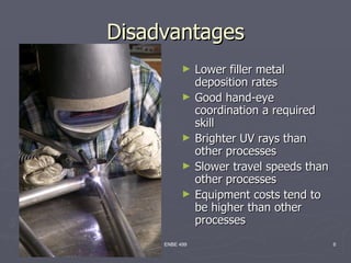
- TIG welding uses a non-consumable tungsten electrode and filler metal is added manually under an inert gas shield.
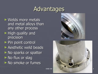
- It allows welding of more metals than other processes with high quality, precision welds and control.
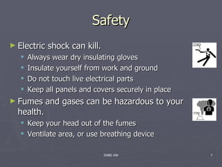
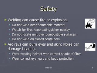
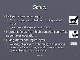
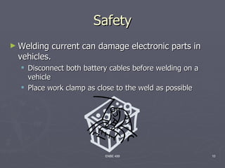
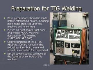
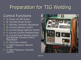
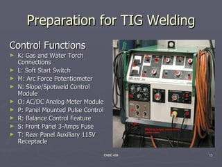
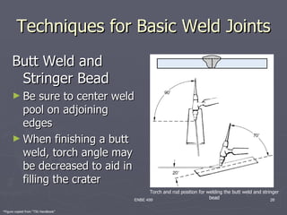
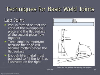
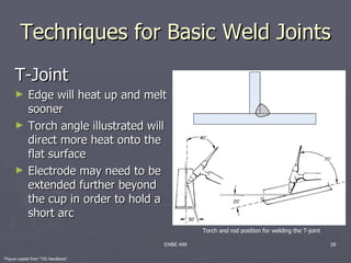
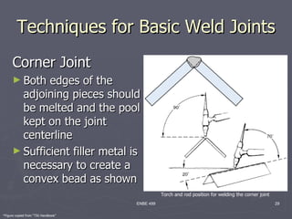
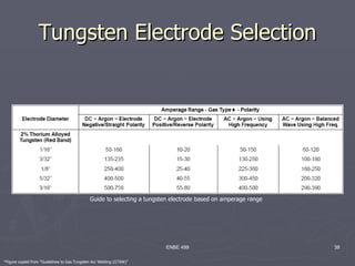
- Safety, equipment setup, techniques for different joints, parameters, and tungsten selection are discussed.
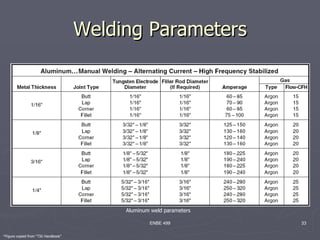
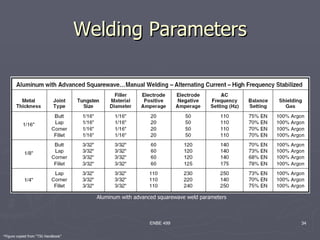
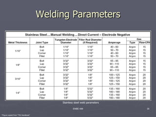
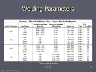
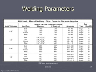
- Tables provide guidelines for welding different metals like aluminum, stainless steel, titanium and mild steel.