Downloaded 1,503 times


![Working principle
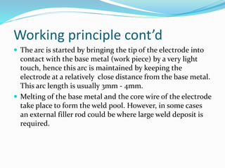
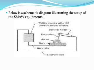
Current flows in through the cables (ground cable and
the hot cable) from the power source (AC/DC) which
the circuit is completed when the electrode tip comes
in contact with the surface of the work piece as will be
seen in the diagram that will be displayed in later slide.
The heat is simply generated at the meeting point
between the electrode an d the work pieces (arc).
The heat input can however be calculated using the
formula H=[(60EI)/(1000S)] Kj/in](https://image.slidesharecdn.com/shieldedmetalarcwelding-151023083113-lva1-app6892/85/Shielded-Metal-Arc-Welding-4-320.jpg)

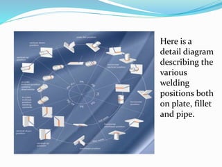


The document discusses Shielded Metal Arc Welding (SMAW), highlighting its principles, techniques, and equipment used in construction and fabrication. It outlines the process of creating welds, the types of electrodes available, and common defects associated with SMAW, as well as emphasizing safety measures during the welding process. Variations of SMAW, such as gravity arc welding, and categories of electrodes based on their properties and applications are also detailed.