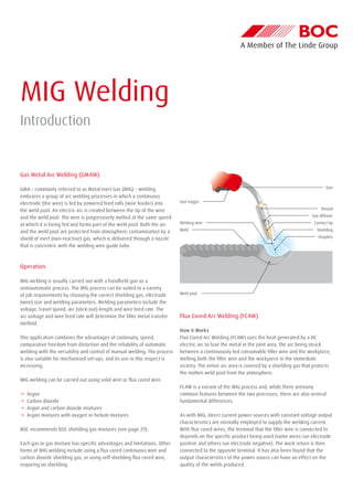
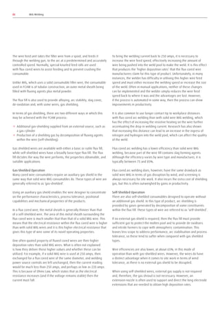
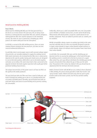
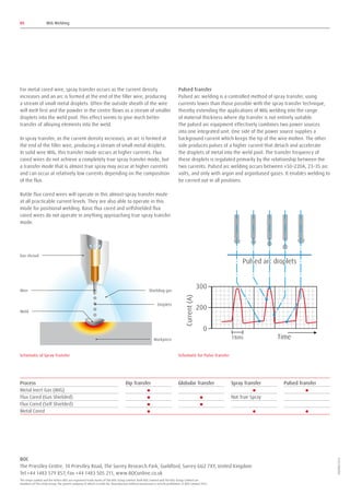
SlideShare a Scribd company logo
1 of 5
Download to read offline
MIG Welding
Introduction
Gas Metal Arc Welding (GMAW)
GMA – commonly referred to as Metal Inert Gas (MIG) – welding
embraces a group of arc welding processes in which a continuous
electrode (the wire) is fed by powered feed rolls (wire feeder) into
the weld pool. An electric arc is created between the tip of the wire
and the weld pool. The wire is progressively melted at the same speed
at which it is being fed and forms part of the weld pool. Both the arc
and the weld pool are protected from atmospheric contamination by a
shield of inert (non-reactive) gas, which is delivered through a nozzle
that is concentric with the welding wire guide tube.
Operation
MIG welding is usually carried out with a handheld gun as a
semiautomatic process. The MIG process can be suited to a variety
of job requirements by choosing the correct shielding gas, electrode
(wire) size and welding parameters. Welding parameters include the
voltage, travel speed, arc (stick-out) length and wire feed rate. The
arc voltage and wire feed rate will determine the filler metal transfer
method.
This application combines the advantages of continuity, speed,
comparative freedom from distortion and the reliability of automatic
welding with the versatility and control of manual welding. The process
is also suitable for mechanised set-ups, and its use in this respect is
increasing.
MIG welding can be carried out using solid wire or flux cored wire.
→→ Argon
→→ Carbon dioxide
→→ Argon and carbon dioxide mixtures
→→ Argon mixtures with oxygen or helium mixtures
BOC recommends BOC shielding gas mixtures (see page 29).
Each gas or gas mixture has specific advantages and limitations. Other
forms of MIG welding include using a flux cored continuous wire and
carbon dioxide shielding gas, or using self-shielding flux cored wire,
requiring no shielding.
Flux Cored Arc Welding (FCAW)
How it Works
Flux Cored Arc Welding (FCAW) uses the heat generated by a DC
electric arc to fuse the metal in the joint area, the arc being struck
between a continuously fed consumable filler wire and the workpiece,
melting both the filler wire and the workpiece in the immediate
vicinity. The entire arc area is covered by a shielding gas that protects
the molten weld pool from the atmosphere.
FCAW is a variant of the MIG process and, while there aremany
common features between the two processes, there are also several
fundamental differences.
As with MIG, direct current power sources with constant voltage output
characteristics are normally employed to supply the welding current.
With flux cored wires, the terminal that the filler wire is connected to
depends on the specific product being used (some wires run electrode
positive and others run electrode negative). The work return is then
connected to the opposite terminal. It has also been found that the
output characteristics of the power source can have an effect on the
quality of the welds produced.
Gun trigger
Gun
Shroud
Gas diffuser
Contact tip
Shielding
Droplets
Welding wire
Weld
Weld pool
The wire feed unit takes the filler wire from a spool, and feeds it
through the welding gun, to the arc at a predetermined and accurately
controlled speed. Normally, special knurled feed rolls are used
with flux cored wires to assist feeding and to prevent crushing the
consumable.
Unlike MIG, which uses a solid consumable filler wire, the consumable
used in FCAW is of tubular construction, an outer metal sheath being
filled with fluxing agents plus metal powder.
The flux fill is also used to provide alloying, arc stability, slag cover,
de-oxidation and, with some wires, gas shielding.
In terms of gas shielding, there are two different ways in which this
may be achieved with the FCAW process:
→→ Additional gas-shielding supplied from an external source, such as
a gas cylinder
→→ Production of a shielding gas by decomposition of fluxing agents
within the wire (self-shielding)
Gas shielded wires are available with either a basic or rutile flux fill,
while self-shielded wires have a broadly basic-type flux fill. The flux
fill dictates the way the wire performs, the properties obtainable, and
suitable applications.
Gas-Shielded Operation
Many cored wire consumables require an auxiliary gas shield in the
same way that solid wire MIG consumables do. These types of wire are
generally referred to as ‘gas-shielded’.
Using an auxiliary gas shield enables the wire designer to concentrate
on the performance characteristics, process tolerance, positional
capabilities and mechanical properties of the products.
In a flux cored wire, the metal sheath is generally thinner than that
of a self-shielded wire. The area of this metal sheath surrounding the
flux cored wire is much smaller that than that of a solid MIG wire. This
means that the electrical resistance within the flux cored wire is higher
than with solid MIG wires and it is this higher electrical resistance that
gives this type of wire some of its novel operating properties.
One often quoted property of fluxed cored wires are their higher
deposition rates than solid MIG wires. What is often not explained
is how they deliver these higher values and whether these can be
utilised. For example, if a solid MIG wire is used at 250 amps, then
exchanged for a flux cored wire of the same diameter, and welding
power source controls are left unchanged, then the current reading
would be much less than 250 amps, and perhaps as low as 220 amps.
This is because of Ohms Law, which states that as the electrical
resistance increases (and if the voltage remains stable) then the
current must fall.
To bring the welding current back to 250 amps, it is necessary to
increase the wire feed speed, effectively increasing the amount of
wire being pushed into the weld pool to make the weld. It is this effect
that produces the ‘higher deposition rates’ that the flux cored wire
manufacturers claim for this type of product. Unfortunately, in many
instances, the welder has difficulty in utilising this higher wire feed
speed and must either increase the welding speed or increase the size
of the weld. Often in manual applications, neither of these changes
can be implemented and the welder simply reduces the wire feed
speed back to where it was and the advantages are lost. However,
if the process is automated in some way, then the process can show
improvements in productivity.
It is also common to use longer contact tip to workplace distances
with flux cored arc welding than with solid wire MIG welding, which
has the effect of increasing the resistive heating on the wire further
accentuating the drop in welding current. Research has also shown
that increasing this distance can lead to an increase in the ingress of
nitrogen and hydrogen into the weld pool, which can affect the quality
of the weld.
Flux cored arc welding has a lower efficiency than solid wire MIG
welding, because part of the wire fill contains slag forming agents.
Although the efficiency varies by wire type and manufacturer, it is
typically between 75 and 85%.
Flux cored arc welding does, however, have the same drawback as
solid wire MIG in terms of gas disruption by wind, and screening is
always necessary for site work. It also incurs the extra cost of shielding
gas, but this is often outweighed by gains in productivity.
Self-Shielded Operation
There are also self-shielded consumables designed to operate without
an additional gas shield. In this type of product, arc shielding is
provided by gases generated by decomposition of some constituents
within the flux fill. These types of wire are referred to as ‘self-shielded’.
If no external gas shield is required, then the flux fill must provide
sufficient gas to protect the molten pool and to provide de-oxidisers
and nitride formers to cope with atmospheric contamination. This
leaves less scope to address performance, arc stabilisation and process
tolerance, so these tend to suffer when compared with gas shielded
types.
Wire efficiencies are also lower, at about 65%, in this mode of
operation than with gas-shielded wires. However, the wires do have
a distinct advantage when it comes to site work in terms of wind
tolerance, as there is no external gas shield to be disrupted.
When using self-shielded wires, external gas supply is not required
and, therefore, the gas shroud is not necessary. However, an
extension nozzle is often used to support and direct the long electrode
extensions that are needed to obtain high deposition rates.
02 MIG Welding
Metal Cored Arc Welding (MCAW)
How it Works
Metal Cored Arc Welding (MCAW) uses the heat generated by a
DC electric arc to fuse metal in the joint area, the arc being struck
between a continuously fed consumable filler wire and the workpiece,
melting both the filler wire and the workpiece in the immediate
vicinity. The entire arc area is covered by a shielding gas, which
protects the molten weld pool from the atmosphere.
As MCAW is a variant of the MIG welding process, there are many
common features between the two processes, but there are also
several fundamental differences.
As with MIG, direct current power sources with constant voltage output
characteristics are normally employed to supply the welding current.
With metal cored wires, the terminal that the filler wire is connected to
depends on the specific product being used. (Some wires are designed
to run on electrode positive, while others run on electrode negative,
and some run on either.) The work return lead is then connected to the
opposite terminal. Electrode negative operation will usually give better
positional welding characteristics.
The output characteristics of the power source can have an effect on
the quality of the welds produced.
The wire feed unit takes the filler wire from a spool or bulk pack, and
feeds it through the welding gun to the arc at a predetermined and
accurately controlled speed. Normally, special knurled feed rolls are
used with metal cored wires to assist feeding and to prevent crushing
the consumable.
Unlike MIG, which uses a solid consumable filler wire, the consumable
used in MCAW is of tubular construction, an outer metal sheath being
filled entirely with metal powder, except for a small amount of non-
metallic compounds. These are added to provide some arc stability and
de-oxidation.
MCAW consumables always require an auxiliary gas shield in the same
way that solid MIG wires do. Wires are normally designed to operate
in argon-carbon dioxide or argon-carbon dioxide-oxygen mixtures or
carbon dioxide. Argon-rich mixtures tend to produce lower fume levels
than carbon dioxide.
As with MIG, the consumable filler wire and the shielding gas are
directed into the arc area by the welding gun. In the head of the gun,
the welding current is transferred to the wire by means of a copper
alloy contact tip, and a gas diffuser distributes the shielding gas evenly
around a shroud which then allows the gas to flow over the weld
area. The position of the contact tip relative to the gas shroud may be
adjusted to limit the minimum electrode extension.
Modes of metal transfer with MCAW are very similar to those obtained
in MIG welding, the process being operable in both ‘dip transfer’ and
‘spray transfer’ modes. Metal cored wires may also be used in pulse
transfer mode at low mean currents, but this has not been widely
exploited.
03 MIG Welding
Circuit diagram of MIG process
Continuous wire
Gas hose
Gas cylinder
Power source Return cable
Wire feed unit
Power cable
Gun conduit
Welding gun
Arc
WorkpieceEarth clamp
Modes of Metal Transfer
The mode or type of metal transfer in MIG welding depends upon the
current, arc voltage, electrode diameter and type of shielding gas
used. In general, there are four modes of metal transfer.
Modes of metal transfer with FCAW are similar to those obtained in MIG
welding, but here the mode of transfer is heavily dependent on the
composition of the flux fill, as well as on current and voltage.
The most common modes of transfer in FCAW are:
→→ Dip transfer
→→ Globular transfer
→→ Spray transfer
→→ Pulsed arc transfer operation has been applied to flux cored wires
but, as yet, is not widely used because the other transfer modes are
giving users what they require in most cases.
Gas shielded wires are available with either a basic or rutile flux fill,
while self-shielded wires have a broadly basic-type flux fill. The flux
fill dictates the way the wire performs, the properties obtainable, and
suitable applications.
Dip Transfer
Also known as short-circuiting arc or short-arc, this is an allpositional
process, using low heat input. The use of relatively low current and
arc voltage settings cause the electrode to intermittently short-circuit
with the weld pool at a controlled frequency. Metal is transferred by
the wire tip actually dipping into the weld pool and the short-circuit
current is sufficient to allow the arc to be re-established. This short-
circuiting mode of metal transfer effectively extends the range of MIG
welding to lower currents so thin sheet material can readily be welded.
The low heat input makes this technique well-suited to the positional
welding of root runs on thick plate, butt welds for bridging over large
gaps and for certain difficult materials where heat input is critical.
Each short-circuit causes the current to rise and the metal fuses off
the end of the electrode. A high short-circuiting frequency gives low
heat input. Dip transfer occurs between ±70–220A, 14–23 arc volts. It is
achieved using shielding gases based on carbon dioxide and argon.
Metal cored wires transfer metal in dip mode at low currents, just like
solid MIG wires. This transfer mode is used for all positional work with
these types of wire.
Globular Transfer
Metal transfer is controlled by slow ejection, resulting in large,
irregularly-shaped ‘globs’ falling into the weld pool under the action
of gravity. Carbon dioxide gas drops are dispersed haphazardly. With
argon-based gases, the drops are not as large and are transferred in
a more axial direction. There is a lot of spatter, especially in carbon
dioxide, resulting in greater wire consumption, poor penetration and
poor appearance. Globular transfer occurs between the dip and spray
ranges. This mode of transfer is not recommended for normal
welding applications and may be corrected when encountered by
either decreasing the arc voltage or increasing the amperage. Globular
transfer can take place with any electrode diameter.
Basic flux cored wires tend to operate in a globular mode or in a
globular-spray transfer mode, where larger than normal spray droplets
are propelled across the arc, but they never achieve a true spray
transfer mode. This transfer mode is sometimes referred to as non-axial
globular transfer.
Self-shielded flux cored wires operate in a predominantly
globular transfer mode, although at high currents the wire often
‘explodes’across the arc.
Spray Transfer
In spray transfer, metal is projected by an electromagnetic force from
the wire tip in the form of a continuous stream of discrete droplets
approximately the same size as the wire diameter. High deposition
rates are possible and weld appearance and reliability are good. Most
metals can be welded, but the technique is limited generally to plate
thicknesses greater than 6mm. Spray transfer, due to the tendency of
the large weld pool to spill over, cannot normally be used for positional
welding. The main exception is aluminium and its alloys where,
primarily because of its low density and high thermal conductivity,
spray transfer in position can be carried out.
The current flows continuously because the high voltage maintains
a long arc and short-circuiting cannot take place. It occurs best with
argon-based gases.
In solid wire MIG, as the current is increased, dip transfer passes into
spray transfer via a transitional globular transfer mode. With metal
cored wires there is virtually a direct transition from dip transfer to
spray transfer as the current is increased.
04 MIG Welding
Schematic of Globular Transfer
Spatter
Workpiece
Large droplet
For metal cored wire, spray transfer occurs as the current density
increases and an arc is formed at the end of the filler wire, producing
a stream of small metal droplets. Often the outside sheath of the wire
will melt first and the powder in the centre flows as a stream of smaller
droplets into the weld pool. This effect seems to give much better
transfer of alloying elements into the weld.
In spray transfer, as the current density increases, an arc is formed at
the end of the filler wire, producing a stream of small metal droplets.
In solid wire MIG, this transfer mode occurs at higher currents. Flux
cored wires do not achieve a completely true spray transfer mode, but
a transfer mode that is almost true spray may occur at higher currents
and can occur at relatively low currents depending on the composition
of the flux.
Rutile flux cored wires will operate in this almost-spray transfer mode
at all practicable current levels. They are also able to operate in this
mode for positional welding. Basic flux cored and selfshielded flux
cored wires do not operate in anything approaching true spray transfer
mode.
Pulsed Transfer
Pulsed arc welding is a controlled method of spray transfer, using
currents lower than those possible with the spray transfer technique,
thereby extending the applications of MIG welding into the range
of material thickness where dip transfer is not entirely suitable.
The pulsed arc equipment effectively combines two power sources
into one integrated unit. One side of the power source supplies a
background current which keeps the tip of the wire molten. The other
side produces pulses of a higher current that detach and accelerate
the droplets of metal into the weld pool. The transfer frequency of
these droplets is regulated primarily by the relationship between the
two currents. Pulsed arc welding occurs between ±50–220A, 23–35 arc
volts, and only with argon and argonbased gases. It enables welding to
be carried out in all positions.
05 MIG Welding
Process Dip Transfer Globular Transfer Spray Transfer Pulsed Transfer
Metal Inert Gas (MIG)
Flux Cored (Gas Shielded) Not True Spray
Flux Cored (Self Shielded)
Metal Cored
Schematic of Spray Transfer
Shielding gas
Gas shroud
Droplets
Wire
Weld
Workpiece
Schematic for Pulse Transfer
The stripe symbol and the letters BOC are registered trade marks of The BOC Group Limited. Both BOC Limited and The BOC Group Limited are
members of The Linde Group, the parent company of which is Linde AG. Reproduction without permission is strictly prohibited. © BOC Limited 2013
BOC
The Priestley Centre, 10 Priestley Road, The Surrey Research Park, Guildford, Surrey GU2 7XY, United Kingdom
Tel +44 1483 579 857, Fax +44 1483 505 211, www.BOConline.co.uk
503780/1213

More Related Content

What's hot (20)

Gas Metal Arc welding
Gas Metal Arc welding Gas Metal Arc welding
Gas Metal Arc welding
 
Gmaw
GmawGmaw
Gmaw
 
Gas metal arc welding
Gas metal arc weldingGas metal arc welding
Gas metal arc welding
 
Pulsed mig welding
Pulsed mig weldingPulsed mig welding
Pulsed mig welding
 
gmaw mig welding
gmaw  mig weldinggmaw  mig welding
gmaw mig welding
 
Gmaw transfer modes
Gmaw transfer modesGmaw transfer modes
Gmaw transfer modes
 
MIG/TIG - Welding Consumables
MIG/TIG - Welding ConsumablesMIG/TIG - Welding Consumables
MIG/TIG - Welding Consumables
 
Mig welding(edit)
Mig welding(edit)Mig welding(edit)
Mig welding(edit)
 
Presentation on mig welding
Presentation on mig weldingPresentation on mig welding
Presentation on mig welding
 
Mig welding
Mig weldingMig welding
Mig welding
 
Gmaw
GmawGmaw
Gmaw
 
TALAT Lecture 4201: Arc welding processes: TIG, Plasma arc, MIG
TALAT Lecture 4201: Arc welding processes: TIG, Plasma arc, MIGTALAT Lecture 4201: Arc welding processes: TIG, Plasma arc, MIG
TALAT Lecture 4201: Arc welding processes: TIG, Plasma arc, MIG
 
Gas Metal Arc Welding (GMAW)
Gas Metal Arc Welding (GMAW)Gas Metal Arc Welding (GMAW)
Gas Metal Arc Welding (GMAW)
 
Gass tungsten Arc Welding (GTAW)/ Tungsten Inert Gas Welding (TIG)
Gass tungsten Arc Welding (GTAW)/ Tungsten Inert Gas Welding (TIG) Gass tungsten Arc Welding (GTAW)/ Tungsten Inert Gas Welding (TIG)
Gass tungsten Arc Welding (GTAW)/ Tungsten Inert Gas Welding (TIG)
 
TIG Welding (Tungsten Inert Gas Welding)
TIG Welding (Tungsten Inert Gas Welding) TIG Welding (Tungsten Inert Gas Welding)
TIG Welding (Tungsten Inert Gas Welding)
 
TIG Welding
TIG WeldingTIG Welding
TIG Welding
 
Tig welding
Tig welding Tig welding
Tig welding
 
Gas Tungsten Arc Welding (ASM Handbook)
Gas Tungsten Arc Welding (ASM Handbook)Gas Tungsten Arc Welding (ASM Handbook)
Gas Tungsten Arc Welding (ASM Handbook)
 
Tig
TigTig
Tig
 
Application of TIG & MIG Welding in Manufacturing
Application of TIG & MIG Welding in ManufacturingApplication of TIG & MIG Welding in Manufacturing
Application of TIG & MIG Welding in Manufacturing
 

Viewers also liked (9)

MIG Welding
MIG WeldingMIG Welding
MIG Welding
 
Mig
MigMig
Mig
 
Gtaw 03
Gtaw 03Gtaw 03
Gtaw 03
 
Tig welding
Tig weldingTig welding
Tig welding
 
Mig welding. Manufacturing Process
Mig welding. Manufacturing ProcessMig welding. Manufacturing Process
Mig welding. Manufacturing Process
 
Tungsten Inert Gas Welding
Tungsten Inert Gas WeldingTungsten Inert Gas Welding
Tungsten Inert Gas Welding
 
Metal inert gas welding
Metal inert gas weldingMetal inert gas welding
Metal inert gas welding
 
Tig welding
Tig weldingTig welding
Tig welding
 
Welding1
Welding1Welding1
Welding1
 

Similar to MIG Welding Guide to Gas Metal Arc Welding (GMAW

Flux cored arc welding
Flux cored arc weldingFlux cored arc welding
Flux cored arc weldingfaheem maqsood
 
Arc Welding Processes 2 1
Arc Welding Processes 2 1Arc Welding Processes 2 1
Arc Welding Processes 2 1guest5be29
 
L2-Arc Welding Process.pptx
L2-Arc Welding Process.pptxL2-Arc Welding Process.pptx
L2-Arc Welding Process.pptxMahesh Goswami
 
The study of microstructural and mechanical properties of butt-welded plates ...
The study of microstructural and mechanical properties of butt-welded plates ...The study of microstructural and mechanical properties of butt-welded plates ...
The study of microstructural and mechanical properties of butt-welded plates ...IRJET Journal
 
Unit-V Joining Process-08 n.pptxjuahhajjjwjj
Unit-V Joining Process-08 n.pptxjuahhajjjwjjUnit-V Joining Process-08 n.pptxjuahhajjjwjj
Unit-V Joining Process-08 n.pptxjuahhajjjwjjSakshiSalunkhe24
 
EXPERIMENTAL OPTIMIZATION OF MILD STEEL ON TIG WELDING
EXPERIMENTAL OPTIMIZATION OF MILD STEEL ON TIG WELDINGEXPERIMENTAL OPTIMIZATION OF MILD STEEL ON TIG WELDING
EXPERIMENTAL OPTIMIZATION OF MILD STEEL ON TIG WELDINGIRJET Journal
 
Welding process By Engr. Muhammad Shahbaz
Welding process By Engr. Muhammad Shahbaz Welding process By Engr. Muhammad Shahbaz
Welding process By Engr. Muhammad Shahbaz Engr. Muhammad Shahbaz
 
Arc welding, smaw, saw, mig, tig advantage
Arc welding, smaw, saw, mig, tig advantageArc welding, smaw, saw, mig, tig advantage
Arc welding, smaw, saw, mig, tig advantagemahendra singh
 
A PROJECT REPORT PIISW
A PROJECT REPORT PIISWA PROJECT REPORT PIISW
A PROJECT REPORT PIISWGithin Geo
 
Final MIG,TIG.GTAW PPt.pptx
Final MIG,TIG.GTAW PPt.pptxFinal MIG,TIG.GTAW PPt.pptx
Final MIG,TIG.GTAW PPt.pptxBarsena
 
experimental investigation of gas metal arc welding (gmaw) on 2.25
 experimental investigation of gas metal arc welding (gmaw) on 2.25 experimental investigation of gas metal arc welding (gmaw) on 2.25
experimental investigation of gas metal arc welding (gmaw) on 2.25NEERAJKUMAR1898
 
Welding Assignment
Welding AssignmentWelding Assignment
Welding AssignmentDil Shah
 
Welding process /certified fixed orthodontic courses by Indian dental acad...
Welding process    /certified fixed orthodontic courses by Indian dental acad...Welding process    /certified fixed orthodontic courses by Indian dental acad...
Welding process /certified fixed orthodontic courses by Indian dental acad...Indian dental academy
 
Joining processes welding, soldering & Brazing
Joining processes  welding, soldering & BrazingJoining processes  welding, soldering & Brazing
Joining processes welding, soldering & Brazingself employer
 

Similar to MIG Welding Guide to Gas Metal Arc Welding (GMAW (20)

Flux cored arc welding
Flux cored arc weldingFlux cored arc welding
Flux cored arc welding
 
Arc Welding Processes 2 1
Arc Welding Processes 2 1Arc Welding Processes 2 1
Arc Welding Processes 2 1
 
Welding handbook.pdf
Welding handbook.pdfWelding handbook.pdf
Welding handbook.pdf
 
L2-Arc Welding Process.pptx
L2-Arc Welding Process.pptxL2-Arc Welding Process.pptx
L2-Arc Welding Process.pptx
 
The study of microstructural and mechanical properties of butt-welded plates ...
The study of microstructural and mechanical properties of butt-welded plates ...The study of microstructural and mechanical properties of butt-welded plates ...
The study of microstructural and mechanical properties of butt-welded plates ...
 
Unit-V Joining Process-08 n.pptxjuahhajjjwjj
Unit-V Joining Process-08 n.pptxjuahhajjjwjjUnit-V Joining Process-08 n.pptxjuahhajjjwjj
Unit-V Joining Process-08 n.pptxjuahhajjjwjj
 
EXPERIMENTAL OPTIMIZATION OF MILD STEEL ON TIG WELDING
EXPERIMENTAL OPTIMIZATION OF MILD STEEL ON TIG WELDINGEXPERIMENTAL OPTIMIZATION OF MILD STEEL ON TIG WELDING
EXPERIMENTAL OPTIMIZATION OF MILD STEEL ON TIG WELDING
 
Arc Welding
Arc WeldingArc Welding
Arc Welding
 
Welding process By Engr. Muhammad Shahbaz
Welding process By Engr. Muhammad Shahbaz Welding process By Engr. Muhammad Shahbaz
Welding process By Engr. Muhammad Shahbaz
 
Arc welding, smaw, saw, mig, tig advantage
Arc welding, smaw, saw, mig, tig advantageArc welding, smaw, saw, mig, tig advantage
Arc welding, smaw, saw, mig, tig advantage
 
final paper of GMAW
final paper of GMAWfinal paper of GMAW
final paper of GMAW
 
A PROJECT REPORT PIISW
A PROJECT REPORT PIISWA PROJECT REPORT PIISW
A PROJECT REPORT PIISW
 
Welding (WorkShop) Assig # 1
Welding (WorkShop) Assig # 1Welding (WorkShop) Assig # 1
Welding (WorkShop) Assig # 1
 
Presentation on welding
Presentation on weldingPresentation on welding
Presentation on welding
 
Final MIG,TIG.GTAW PPt.pptx
Final MIG,TIG.GTAW PPt.pptxFinal MIG,TIG.GTAW PPt.pptx
Final MIG,TIG.GTAW PPt.pptx
 
experimental investigation of gas metal arc welding (gmaw) on 2.25
 experimental investigation of gas metal arc welding (gmaw) on 2.25 experimental investigation of gas metal arc welding (gmaw) on 2.25
experimental investigation of gas metal arc welding (gmaw) on 2.25
 
Welding Assignment
Welding AssignmentWelding Assignment
Welding Assignment
 
Welding iv
Welding   ivWelding   iv
Welding iv
 
Welding process /certified fixed orthodontic courses by Indian dental acad...
Welding process    /certified fixed orthodontic courses by Indian dental acad...Welding process    /certified fixed orthodontic courses by Indian dental acad...
Welding process /certified fixed orthodontic courses by Indian dental acad...
 
Joining processes welding, soldering & Brazing
Joining processes  welding, soldering & BrazingJoining processes  welding, soldering & Brazing
Joining processes welding, soldering & Brazing
 

Recently uploaded

Microscopic Analysis of Ceramic Materials.pptx
Microscopic Analysis of Ceramic Materials.pptxMicroscopic Analysis of Ceramic Materials.pptx
Microscopic Analysis of Ceramic Materials.pptxpurnimasatapathy1234
 
Processing & Properties of Floor and Wall Tiles.pptx
Processing & Properties of Floor and Wall Tiles.pptxProcessing & Properties of Floor and Wall Tiles.pptx
Processing & Properties of Floor and Wall Tiles.pptxpranjaldaimarysona
 
GDSC ASEB Gen AI study jams presentation
GDSC ASEB Gen AI study jams presentationGDSC ASEB Gen AI study jams presentation
GDSC ASEB Gen AI study jams presentationGDSCAESB
 
College Call Girls Nashik Nehal 7001305949 Independent Escort Service Nashik
College Call Girls Nashik Nehal 7001305949 Independent Escort Service NashikCollege Call Girls Nashik Nehal 7001305949 Independent Escort Service Nashik
College Call Girls Nashik Nehal 7001305949 Independent Escort Service NashikCall Girls in Nagpur High Profile
 
MANUFACTURING PROCESS-II UNIT-2 LATHE MACHINE
MANUFACTURING PROCESS-II UNIT-2 LATHE MACHINEMANUFACTURING PROCESS-II UNIT-2 LATHE MACHINE
MANUFACTURING PROCESS-II UNIT-2 LATHE MACHINESIVASHANKAR N
 
HARMONY IN THE NATURE AND EXISTENCE - Unit-IV
HARMONY IN THE NATURE AND EXISTENCE - Unit-IVHARMONY IN THE NATURE AND EXISTENCE - Unit-IV
HARMONY IN THE NATURE AND EXISTENCE - Unit-IVRajaP95
 
Structural Analysis and Design of Foundations: A Comprehensive Handbook for S...
Structural Analysis and Design of Foundations: A Comprehensive Handbook for S...Structural Analysis and Design of Foundations: A Comprehensive Handbook for S...
Structural Analysis and Design of Foundations: A Comprehensive Handbook for S...Dr.Costas Sachpazis
 
Architect Hassan Khalil Portfolio for 2024
Architect Hassan Khalil Portfolio for 2024Architect Hassan Khalil Portfolio for 2024
Architect Hassan Khalil Portfolio for 2024hassan khalil
 
Analog to Digital and Digital to Analog Converter
Analog to Digital and Digital to Analog ConverterAnalog to Digital and Digital to Analog Converter
Analog to Digital and Digital to Analog ConverterAbhinavSharma374939
 
Call Girls in Nagpur Suman Call 7001035870 Meet With Nagpur Escorts
Call Girls in Nagpur Suman Call 7001035870 Meet With Nagpur EscortsCall Girls in Nagpur Suman Call 7001035870 Meet With Nagpur Escorts
Call Girls in Nagpur Suman Call 7001035870 Meet With Nagpur EscortsCall Girls in Nagpur High Profile
 
(PRIYA) Rajgurunagar Call Girls Just Call 7001035870 [ Cash on Delivery ] Pun...
(PRIYA) Rajgurunagar Call Girls Just Call 7001035870 [ Cash on Delivery ] Pun...(PRIYA) Rajgurunagar Call Girls Just Call 7001035870 [ Cash on Delivery ] Pun...
(PRIYA) Rajgurunagar Call Girls Just Call 7001035870 [ Cash on Delivery ] Pun...ranjana rawat
 
Introduction to Multiple Access Protocol.pptx
Introduction to Multiple Access Protocol.pptxIntroduction to Multiple Access Protocol.pptx
Introduction to Multiple Access Protocol.pptxupamatechverse
 
What are the advantages and disadvantages of membrane structures.pptx
What are the advantages and disadvantages of membrane structures.pptxWhat are the advantages and disadvantages of membrane structures.pptx
What are the advantages and disadvantages of membrane structures.pptxwendy cai
 
Introduction and different types of Ethernet.pptx
Introduction and different types of Ethernet.pptxIntroduction and different types of Ethernet.pptx
Introduction and different types of Ethernet.pptxupamatechverse
 
MANUFACTURING PROCESS-II UNIT-5 NC MACHINE TOOLS
MANUFACTURING PROCESS-II UNIT-5 NC MACHINE TOOLSMANUFACTURING PROCESS-II UNIT-5 NC MACHINE TOOLS
MANUFACTURING PROCESS-II UNIT-5 NC MACHINE TOOLSSIVASHANKAR N
 
Introduction to IEEE STANDARDS and its different types.pptx
Introduction to IEEE STANDARDS and its different types.pptxIntroduction to IEEE STANDARDS and its different types.pptx
Introduction to IEEE STANDARDS and its different types.pptxupamatechverse
 
HARDNESS, FRACTURE TOUGHNESS AND STRENGTH OF CERAMICS
HARDNESS, FRACTURE TOUGHNESS AND STRENGTH OF CERAMICSHARDNESS, FRACTURE TOUGHNESS AND STRENGTH OF CERAMICS
HARDNESS, FRACTURE TOUGHNESS AND STRENGTH OF CERAMICSRajkumarAkumalla
 
VIP Call Girls Service Hitech City Hyderabad Call +91-8250192130
VIP Call Girls Service Hitech City Hyderabad Call +91-8250192130VIP Call Girls Service Hitech City Hyderabad Call +91-8250192130
VIP Call Girls Service Hitech City Hyderabad Call +91-8250192130Suhani Kapoor
 

Recently uploaded (20)

Microscopic Analysis of Ceramic Materials.pptx
Microscopic Analysis of Ceramic Materials.pptxMicroscopic Analysis of Ceramic Materials.pptx
Microscopic Analysis of Ceramic Materials.pptx
 
Processing & Properties of Floor and Wall Tiles.pptx
Processing & Properties of Floor and Wall Tiles.pptxProcessing & Properties of Floor and Wall Tiles.pptx
Processing & Properties of Floor and Wall Tiles.pptx
 
9953056974 Call Girls In South Ex, Escorts (Delhi) NCR.pdf
9953056974 Call Girls In South Ex, Escorts (Delhi) NCR.pdf9953056974 Call Girls In South Ex, Escorts (Delhi) NCR.pdf
9953056974 Call Girls In South Ex, Escorts (Delhi) NCR.pdf
 
GDSC ASEB Gen AI study jams presentation
GDSC ASEB Gen AI study jams presentationGDSC ASEB Gen AI study jams presentation
GDSC ASEB Gen AI study jams presentation
 
College Call Girls Nashik Nehal 7001305949 Independent Escort Service Nashik
College Call Girls Nashik Nehal 7001305949 Independent Escort Service NashikCollege Call Girls Nashik Nehal 7001305949 Independent Escort Service Nashik
College Call Girls Nashik Nehal 7001305949 Independent Escort Service Nashik
 
MANUFACTURING PROCESS-II UNIT-2 LATHE MACHINE
MANUFACTURING PROCESS-II UNIT-2 LATHE MACHINEMANUFACTURING PROCESS-II UNIT-2 LATHE MACHINE
MANUFACTURING PROCESS-II UNIT-2 LATHE MACHINE
 
HARMONY IN THE NATURE AND EXISTENCE - Unit-IV
HARMONY IN THE NATURE AND EXISTENCE - Unit-IVHARMONY IN THE NATURE AND EXISTENCE - Unit-IV
HARMONY IN THE NATURE AND EXISTENCE - Unit-IV
 
Structural Analysis and Design of Foundations: A Comprehensive Handbook for S...
Structural Analysis and Design of Foundations: A Comprehensive Handbook for S...Structural Analysis and Design of Foundations: A Comprehensive Handbook for S...
Structural Analysis and Design of Foundations: A Comprehensive Handbook for S...
 
Architect Hassan Khalil Portfolio for 2024
Architect Hassan Khalil Portfolio for 2024Architect Hassan Khalil Portfolio for 2024
Architect Hassan Khalil Portfolio for 2024
 
Analog to Digital and Digital to Analog Converter
Analog to Digital and Digital to Analog ConverterAnalog to Digital and Digital to Analog Converter
Analog to Digital and Digital to Analog Converter
 
Call Girls in Nagpur Suman Call 7001035870 Meet With Nagpur Escorts
Call Girls in Nagpur Suman Call 7001035870 Meet With Nagpur EscortsCall Girls in Nagpur Suman Call 7001035870 Meet With Nagpur Escorts
Call Girls in Nagpur Suman Call 7001035870 Meet With Nagpur Escorts
 
(PRIYA) Rajgurunagar Call Girls Just Call 7001035870 [ Cash on Delivery ] Pun...
(PRIYA) Rajgurunagar Call Girls Just Call 7001035870 [ Cash on Delivery ] Pun...(PRIYA) Rajgurunagar Call Girls Just Call 7001035870 [ Cash on Delivery ] Pun...
(PRIYA) Rajgurunagar Call Girls Just Call 7001035870 [ Cash on Delivery ] Pun...
 
Introduction to Multiple Access Protocol.pptx
Introduction to Multiple Access Protocol.pptxIntroduction to Multiple Access Protocol.pptx
Introduction to Multiple Access Protocol.pptx
 
What are the advantages and disadvantages of membrane structures.pptx
What are the advantages and disadvantages of membrane structures.pptxWhat are the advantages and disadvantages of membrane structures.pptx
What are the advantages and disadvantages of membrane structures.pptx
 
Introduction and different types of Ethernet.pptx
Introduction and different types of Ethernet.pptxIntroduction and different types of Ethernet.pptx
Introduction and different types of Ethernet.pptx
 
MANUFACTURING PROCESS-II UNIT-5 NC MACHINE TOOLS
MANUFACTURING PROCESS-II UNIT-5 NC MACHINE TOOLSMANUFACTURING PROCESS-II UNIT-5 NC MACHINE TOOLS
MANUFACTURING PROCESS-II UNIT-5 NC MACHINE TOOLS
 
Exploring_Network_Security_with_JA3_by_Rakesh Seal.pptx
Exploring_Network_Security_with_JA3_by_Rakesh Seal.pptxExploring_Network_Security_with_JA3_by_Rakesh Seal.pptx
Exploring_Network_Security_with_JA3_by_Rakesh Seal.pptx
 
Introduction to IEEE STANDARDS and its different types.pptx
Introduction to IEEE STANDARDS and its different types.pptxIntroduction to IEEE STANDARDS and its different types.pptx
Introduction to IEEE STANDARDS and its different types.pptx
 
HARDNESS, FRACTURE TOUGHNESS AND STRENGTH OF CERAMICS
HARDNESS, FRACTURE TOUGHNESS AND STRENGTH OF CERAMICSHARDNESS, FRACTURE TOUGHNESS AND STRENGTH OF CERAMICS
HARDNESS, FRACTURE TOUGHNESS AND STRENGTH OF CERAMICS
 
VIP Call Girls Service Hitech City Hyderabad Call +91-8250192130
VIP Call Girls Service Hitech City Hyderabad Call +91-8250192130VIP Call Girls Service Hitech City Hyderabad Call +91-8250192130
VIP Call Girls Service Hitech City Hyderabad Call +91-8250192130
 

MIG Welding Guide to Gas Metal Arc Welding (GMAW

  • 1. MIG Welding Introduction Gas Metal Arc Welding (GMAW) GMA – commonly referred to as Metal Inert Gas (MIG) – welding embraces a group of arc welding processes in which a continuous electrode (the wire) is fed by powered feed rolls (wire feeder) into the weld pool. An electric arc is created between the tip of the wire and the weld pool. The wire is progressively melted at the same speed at which it is being fed and forms part of the weld pool. Both the arc and the weld pool are protected from atmospheric contamination by a shield of inert (non-reactive) gas, which is delivered through a nozzle that is concentric with the welding wire guide tube. Operation MIG welding is usually carried out with a handheld gun as a semiautomatic process. The MIG process can be suited to a variety of job requirements by choosing the correct shielding gas, electrode (wire) size and welding parameters. Welding parameters include the voltage, travel speed, arc (stick-out) length and wire feed rate. The arc voltage and wire feed rate will determine the filler metal transfer method. This application combines the advantages of continuity, speed, comparative freedom from distortion and the reliability of automatic welding with the versatility and control of manual welding. The process is also suitable for mechanised set-ups, and its use in this respect is increasing. MIG welding can be carried out using solid wire or flux cored wire. →→ Argon →→ Carbon dioxide →→ Argon and carbon dioxide mixtures →→ Argon mixtures with oxygen or helium mixtures BOC recommends BOC shielding gas mixtures (see page 29). Each gas or gas mixture has specific advantages and limitations. Other forms of MIG welding include using a flux cored continuous wire and carbon dioxide shielding gas, or using self-shielding flux cored wire, requiring no shielding. Flux Cored Arc Welding (FCAW) How it Works Flux Cored Arc Welding (FCAW) uses the heat generated by a DC electric arc to fuse the metal in the joint area, the arc being struck between a continuously fed consumable filler wire and the workpiece, melting both the filler wire and the workpiece in the immediate vicinity. The entire arc area is covered by a shielding gas that protects the molten weld pool from the atmosphere. FCAW is a variant of the MIG process and, while there aremany common features between the two processes, there are also several fundamental differences. As with MIG, direct current power sources with constant voltage output characteristics are normally employed to supply the welding current. With flux cored wires, the terminal that the filler wire is connected to depends on the specific product being used (some wires run electrode positive and others run electrode negative). The work return is then connected to the opposite terminal. It has also been found that the output characteristics of the power source can have an effect on the quality of the welds produced. Gun trigger Gun Shroud Gas diffuser Contact tip Shielding Droplets Welding wire Weld Weld pool
  • 2. The wire feed unit takes the filler wire from a spool, and feeds it through the welding gun, to the arc at a predetermined and accurately controlled speed. Normally, special knurled feed rolls are used with flux cored wires to assist feeding and to prevent crushing the consumable. Unlike MIG, which uses a solid consumable filler wire, the consumable used in FCAW is of tubular construction, an outer metal sheath being filled with fluxing agents plus metal powder. The flux fill is also used to provide alloying, arc stability, slag cover, de-oxidation and, with some wires, gas shielding. In terms of gas shielding, there are two different ways in which this may be achieved with the FCAW process: →→ Additional gas-shielding supplied from an external source, such as a gas cylinder →→ Production of a shielding gas by decomposition of fluxing agents within the wire (self-shielding) Gas shielded wires are available with either a basic or rutile flux fill, while self-shielded wires have a broadly basic-type flux fill. The flux fill dictates the way the wire performs, the properties obtainable, and suitable applications. Gas-Shielded Operation Many cored wire consumables require an auxiliary gas shield in the same way that solid wire MIG consumables do. These types of wire are generally referred to as ‘gas-shielded’. Using an auxiliary gas shield enables the wire designer to concentrate on the performance characteristics, process tolerance, positional capabilities and mechanical properties of the products. In a flux cored wire, the metal sheath is generally thinner than that of a self-shielded wire. The area of this metal sheath surrounding the flux cored wire is much smaller that than that of a solid MIG wire. This means that the electrical resistance within the flux cored wire is higher than with solid MIG wires and it is this higher electrical resistance that gives this type of wire some of its novel operating properties. One often quoted property of fluxed cored wires are their higher deposition rates than solid MIG wires. What is often not explained is how they deliver these higher values and whether these can be utilised. For example, if a solid MIG wire is used at 250 amps, then exchanged for a flux cored wire of the same diameter, and welding power source controls are left unchanged, then the current reading would be much less than 250 amps, and perhaps as low as 220 amps. This is because of Ohms Law, which states that as the electrical resistance increases (and if the voltage remains stable) then the current must fall. To bring the welding current back to 250 amps, it is necessary to increase the wire feed speed, effectively increasing the amount of wire being pushed into the weld pool to make the weld. It is this effect that produces the ‘higher deposition rates’ that the flux cored wire manufacturers claim for this type of product. Unfortunately, in many instances, the welder has difficulty in utilising this higher wire feed speed and must either increase the welding speed or increase the size of the weld. Often in manual applications, neither of these changes can be implemented and the welder simply reduces the wire feed speed back to where it was and the advantages are lost. However, if the process is automated in some way, then the process can show improvements in productivity. It is also common to use longer contact tip to workplace distances with flux cored arc welding than with solid wire MIG welding, which has the effect of increasing the resistive heating on the wire further accentuating the drop in welding current. Research has also shown that increasing this distance can lead to an increase in the ingress of nitrogen and hydrogen into the weld pool, which can affect the quality of the weld. Flux cored arc welding has a lower efficiency than solid wire MIG welding, because part of the wire fill contains slag forming agents. Although the efficiency varies by wire type and manufacturer, it is typically between 75 and 85%. Flux cored arc welding does, however, have the same drawback as solid wire MIG in terms of gas disruption by wind, and screening is always necessary for site work. It also incurs the extra cost of shielding gas, but this is often outweighed by gains in productivity. Self-Shielded Operation There are also self-shielded consumables designed to operate without an additional gas shield. In this type of product, arc shielding is provided by gases generated by decomposition of some constituents within the flux fill. These types of wire are referred to as ‘self-shielded’. If no external gas shield is required, then the flux fill must provide sufficient gas to protect the molten pool and to provide de-oxidisers and nitride formers to cope with atmospheric contamination. This leaves less scope to address performance, arc stabilisation and process tolerance, so these tend to suffer when compared with gas shielded types. Wire efficiencies are also lower, at about 65%, in this mode of operation than with gas-shielded wires. However, the wires do have a distinct advantage when it comes to site work in terms of wind tolerance, as there is no external gas shield to be disrupted. When using self-shielded wires, external gas supply is not required and, therefore, the gas shroud is not necessary. However, an extension nozzle is often used to support and direct the long electrode extensions that are needed to obtain high deposition rates. 02 MIG Welding
  • 3. Metal Cored Arc Welding (MCAW) How it Works Metal Cored Arc Welding (MCAW) uses the heat generated by a DC electric arc to fuse metal in the joint area, the arc being struck between a continuously fed consumable filler wire and the workpiece, melting both the filler wire and the workpiece in the immediate vicinity. The entire arc area is covered by a shielding gas, which protects the molten weld pool from the atmosphere. As MCAW is a variant of the MIG welding process, there are many common features between the two processes, but there are also several fundamental differences. As with MIG, direct current power sources with constant voltage output characteristics are normally employed to supply the welding current. With metal cored wires, the terminal that the filler wire is connected to depends on the specific product being used. (Some wires are designed to run on electrode positive, while others run on electrode negative, and some run on either.) The work return lead is then connected to the opposite terminal. Electrode negative operation will usually give better positional welding characteristics. The output characteristics of the power source can have an effect on the quality of the welds produced. The wire feed unit takes the filler wire from a spool or bulk pack, and feeds it through the welding gun to the arc at a predetermined and accurately controlled speed. Normally, special knurled feed rolls are used with metal cored wires to assist feeding and to prevent crushing the consumable. Unlike MIG, which uses a solid consumable filler wire, the consumable used in MCAW is of tubular construction, an outer metal sheath being filled entirely with metal powder, except for a small amount of non- metallic compounds. These are added to provide some arc stability and de-oxidation. MCAW consumables always require an auxiliary gas shield in the same way that solid MIG wires do. Wires are normally designed to operate in argon-carbon dioxide or argon-carbon dioxide-oxygen mixtures or carbon dioxide. Argon-rich mixtures tend to produce lower fume levels than carbon dioxide. As with MIG, the consumable filler wire and the shielding gas are directed into the arc area by the welding gun. In the head of the gun, the welding current is transferred to the wire by means of a copper alloy contact tip, and a gas diffuser distributes the shielding gas evenly around a shroud which then allows the gas to flow over the weld area. The position of the contact tip relative to the gas shroud may be adjusted to limit the minimum electrode extension. Modes of metal transfer with MCAW are very similar to those obtained in MIG welding, the process being operable in both ‘dip transfer’ and ‘spray transfer’ modes. Metal cored wires may also be used in pulse transfer mode at low mean currents, but this has not been widely exploited. 03 MIG Welding Circuit diagram of MIG process Continuous wire Gas hose Gas cylinder Power source Return cable Wire feed unit Power cable Gun conduit Welding gun Arc WorkpieceEarth clamp
  • 4. Modes of Metal Transfer The mode or type of metal transfer in MIG welding depends upon the current, arc voltage, electrode diameter and type of shielding gas used. In general, there are four modes of metal transfer. Modes of metal transfer with FCAW are similar to those obtained in MIG welding, but here the mode of transfer is heavily dependent on the composition of the flux fill, as well as on current and voltage. The most common modes of transfer in FCAW are: →→ Dip transfer →→ Globular transfer →→ Spray transfer →→ Pulsed arc transfer operation has been applied to flux cored wires but, as yet, is not widely used because the other transfer modes are giving users what they require in most cases. Gas shielded wires are available with either a basic or rutile flux fill, while self-shielded wires have a broadly basic-type flux fill. The flux fill dictates the way the wire performs, the properties obtainable, and suitable applications. Dip Transfer Also known as short-circuiting arc or short-arc, this is an allpositional process, using low heat input. The use of relatively low current and arc voltage settings cause the electrode to intermittently short-circuit with the weld pool at a controlled frequency. Metal is transferred by the wire tip actually dipping into the weld pool and the short-circuit current is sufficient to allow the arc to be re-established. This short- circuiting mode of metal transfer effectively extends the range of MIG welding to lower currents so thin sheet material can readily be welded. The low heat input makes this technique well-suited to the positional welding of root runs on thick plate, butt welds for bridging over large gaps and for certain difficult materials where heat input is critical. Each short-circuit causes the current to rise and the metal fuses off the end of the electrode. A high short-circuiting frequency gives low heat input. Dip transfer occurs between ±70–220A, 14–23 arc volts. It is achieved using shielding gases based on carbon dioxide and argon. Metal cored wires transfer metal in dip mode at low currents, just like solid MIG wires. This transfer mode is used for all positional work with these types of wire. Globular Transfer Metal transfer is controlled by slow ejection, resulting in large, irregularly-shaped ‘globs’ falling into the weld pool under the action of gravity. Carbon dioxide gas drops are dispersed haphazardly. With argon-based gases, the drops are not as large and are transferred in a more axial direction. There is a lot of spatter, especially in carbon dioxide, resulting in greater wire consumption, poor penetration and poor appearance. Globular transfer occurs between the dip and spray ranges. This mode of transfer is not recommended for normal welding applications and may be corrected when encountered by either decreasing the arc voltage or increasing the amperage. Globular transfer can take place with any electrode diameter. Basic flux cored wires tend to operate in a globular mode or in a globular-spray transfer mode, where larger than normal spray droplets are propelled across the arc, but they never achieve a true spray transfer mode. This transfer mode is sometimes referred to as non-axial globular transfer. Self-shielded flux cored wires operate in a predominantly globular transfer mode, although at high currents the wire often ‘explodes’across the arc. Spray Transfer In spray transfer, metal is projected by an electromagnetic force from the wire tip in the form of a continuous stream of discrete droplets approximately the same size as the wire diameter. High deposition rates are possible and weld appearance and reliability are good. Most metals can be welded, but the technique is limited generally to plate thicknesses greater than 6mm. Spray transfer, due to the tendency of the large weld pool to spill over, cannot normally be used for positional welding. The main exception is aluminium and its alloys where, primarily because of its low density and high thermal conductivity, spray transfer in position can be carried out. The current flows continuously because the high voltage maintains a long arc and short-circuiting cannot take place. It occurs best with argon-based gases. In solid wire MIG, as the current is increased, dip transfer passes into spray transfer via a transitional globular transfer mode. With metal cored wires there is virtually a direct transition from dip transfer to spray transfer as the current is increased. 04 MIG Welding Schematic of Globular Transfer Spatter Workpiece Large droplet
  • 5. For metal cored wire, spray transfer occurs as the current density increases and an arc is formed at the end of the filler wire, producing a stream of small metal droplets. Often the outside sheath of the wire will melt first and the powder in the centre flows as a stream of smaller droplets into the weld pool. This effect seems to give much better transfer of alloying elements into the weld. In spray transfer, as the current density increases, an arc is formed at the end of the filler wire, producing a stream of small metal droplets. In solid wire MIG, this transfer mode occurs at higher currents. Flux cored wires do not achieve a completely true spray transfer mode, but a transfer mode that is almost true spray may occur at higher currents and can occur at relatively low currents depending on the composition of the flux. Rutile flux cored wires will operate in this almost-spray transfer mode at all practicable current levels. They are also able to operate in this mode for positional welding. Basic flux cored and selfshielded flux cored wires do not operate in anything approaching true spray transfer mode. Pulsed Transfer Pulsed arc welding is a controlled method of spray transfer, using currents lower than those possible with the spray transfer technique, thereby extending the applications of MIG welding into the range of material thickness where dip transfer is not entirely suitable. The pulsed arc equipment effectively combines two power sources into one integrated unit. One side of the power source supplies a background current which keeps the tip of the wire molten. The other side produces pulses of a higher current that detach and accelerate the droplets of metal into the weld pool. The transfer frequency of these droplets is regulated primarily by the relationship between the two currents. Pulsed arc welding occurs between ±50–220A, 23–35 arc volts, and only with argon and argonbased gases. It enables welding to be carried out in all positions. 05 MIG Welding Process Dip Transfer Globular Transfer Spray Transfer Pulsed Transfer Metal Inert Gas (MIG) Flux Cored (Gas Shielded) Not True Spray Flux Cored (Self Shielded) Metal Cored Schematic of Spray Transfer Shielding gas Gas shroud Droplets Wire Weld Workpiece Schematic for Pulse Transfer The stripe symbol and the letters BOC are registered trade marks of The BOC Group Limited. Both BOC Limited and The BOC Group Limited are members of The Linde Group, the parent company of which is Linde AG. Reproduction without permission is strictly prohibited. © BOC Limited 2013 BOC The Priestley Centre, 10 Priestley Road, The Surrey Research Park, Guildford, Surrey GU2 7XY, United Kingdom Tel +44 1483 579 857, Fax +44 1483 505 211, www.BOConline.co.uk 503780/1213