This document provides an overview of a welding techniques course, including:
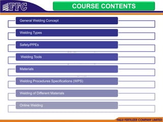
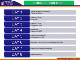
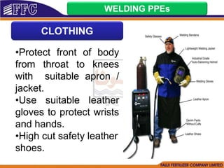
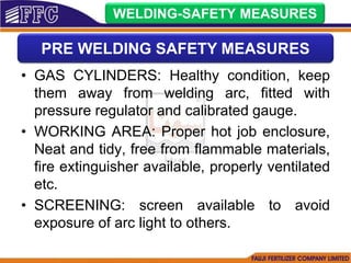
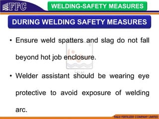
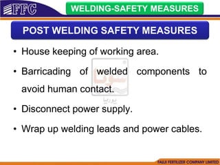
- An 8 day schedule covering general concepts, safety, welding types, tools, materials, procedures and practical demonstrations.
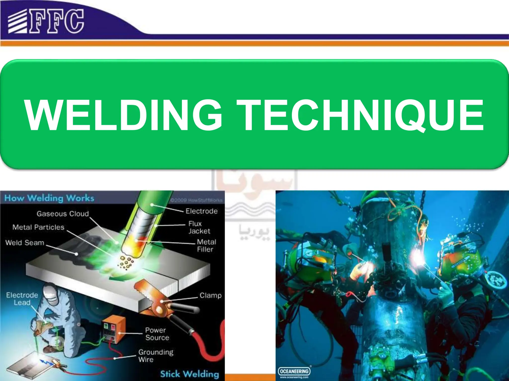
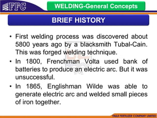
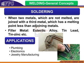
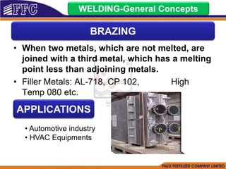
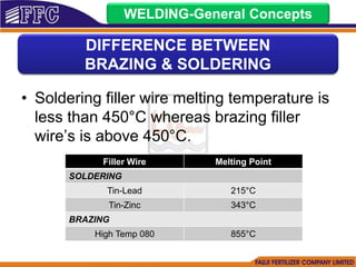
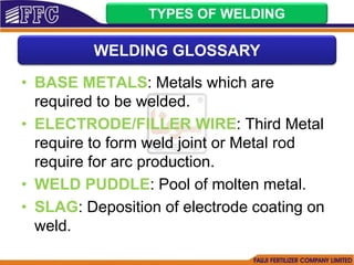
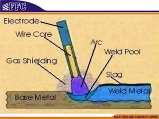
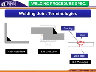
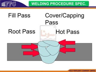
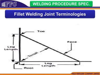
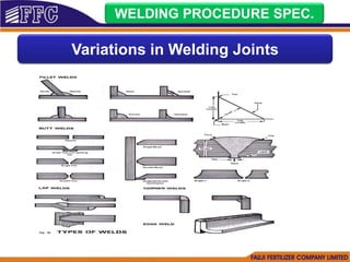
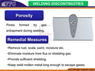
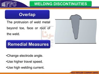
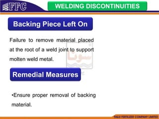
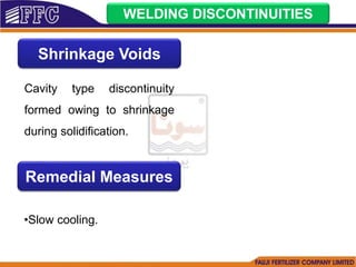
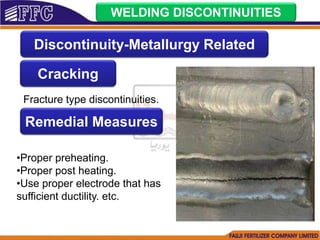
- Summaries of key welding concepts like definitions of welding, brazing, soldering and their differences.
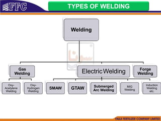
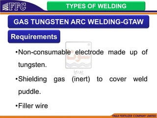
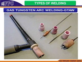
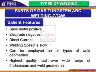
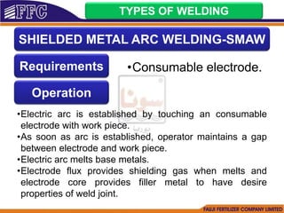
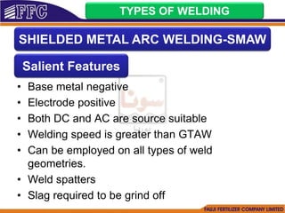
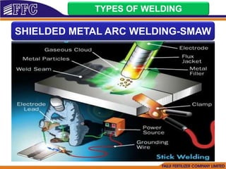
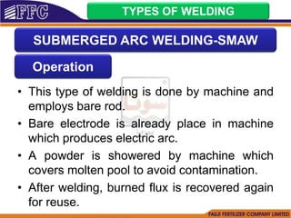
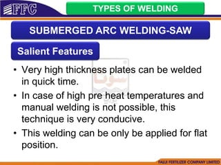
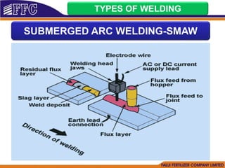
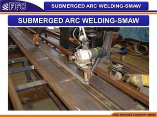
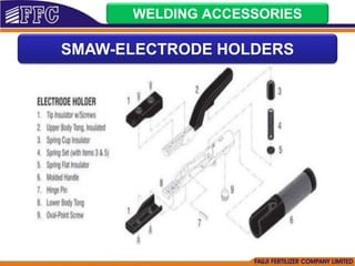
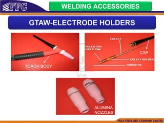
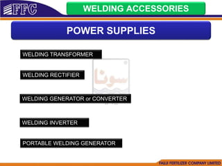
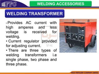
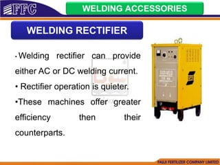
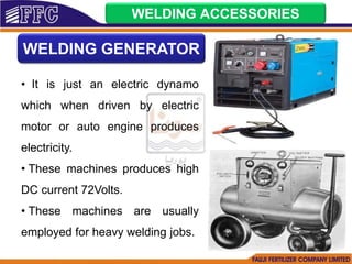
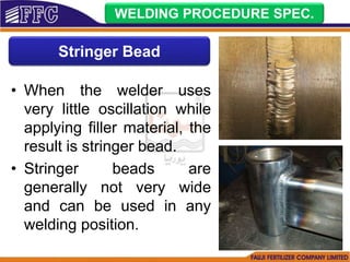
- Descriptions of common welding types like SMAW, GTAW, SAW including their requirements, operation and features.
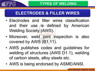
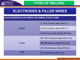
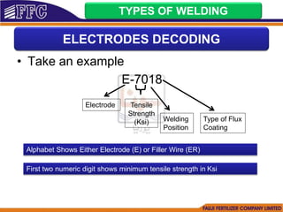
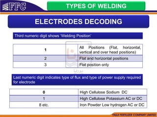
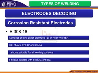
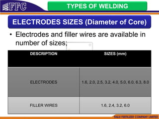
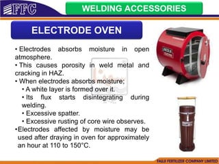
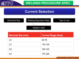
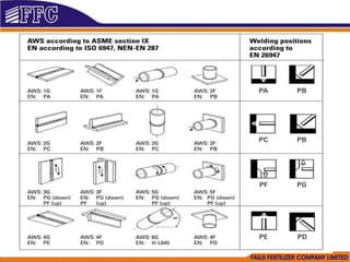
- Details on welding electrodes, fillers, sizes and their coding per AWS standards.