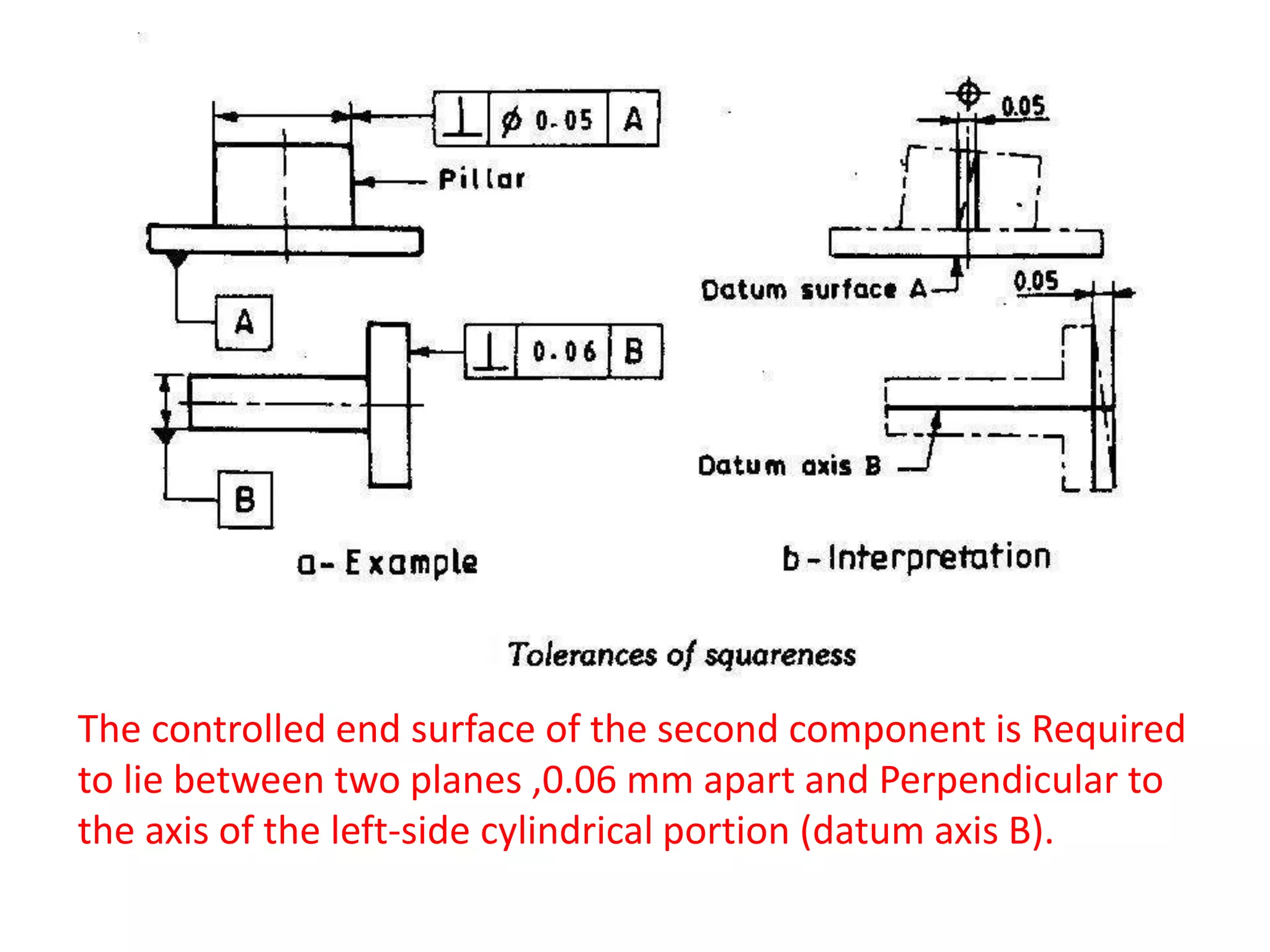
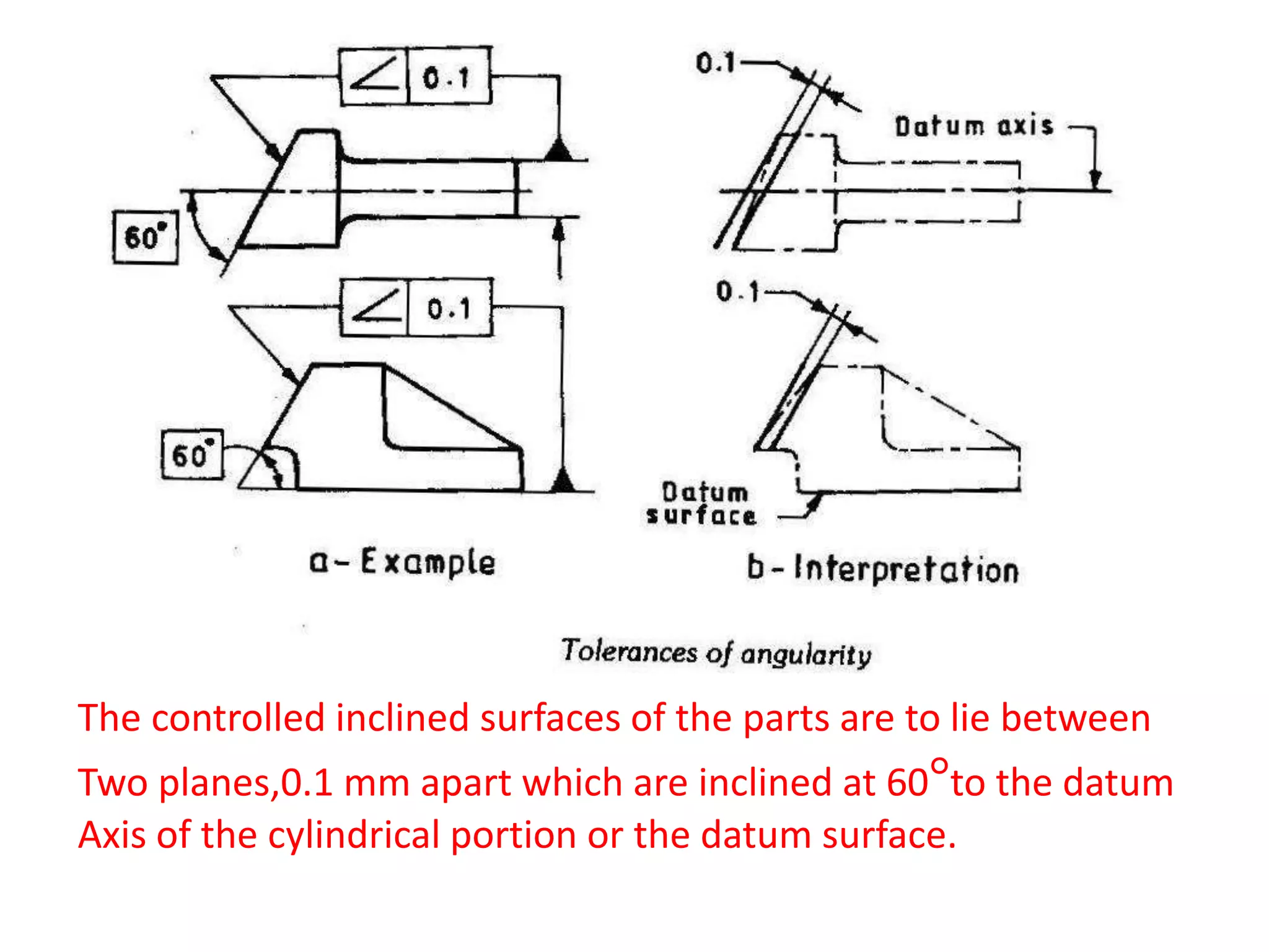
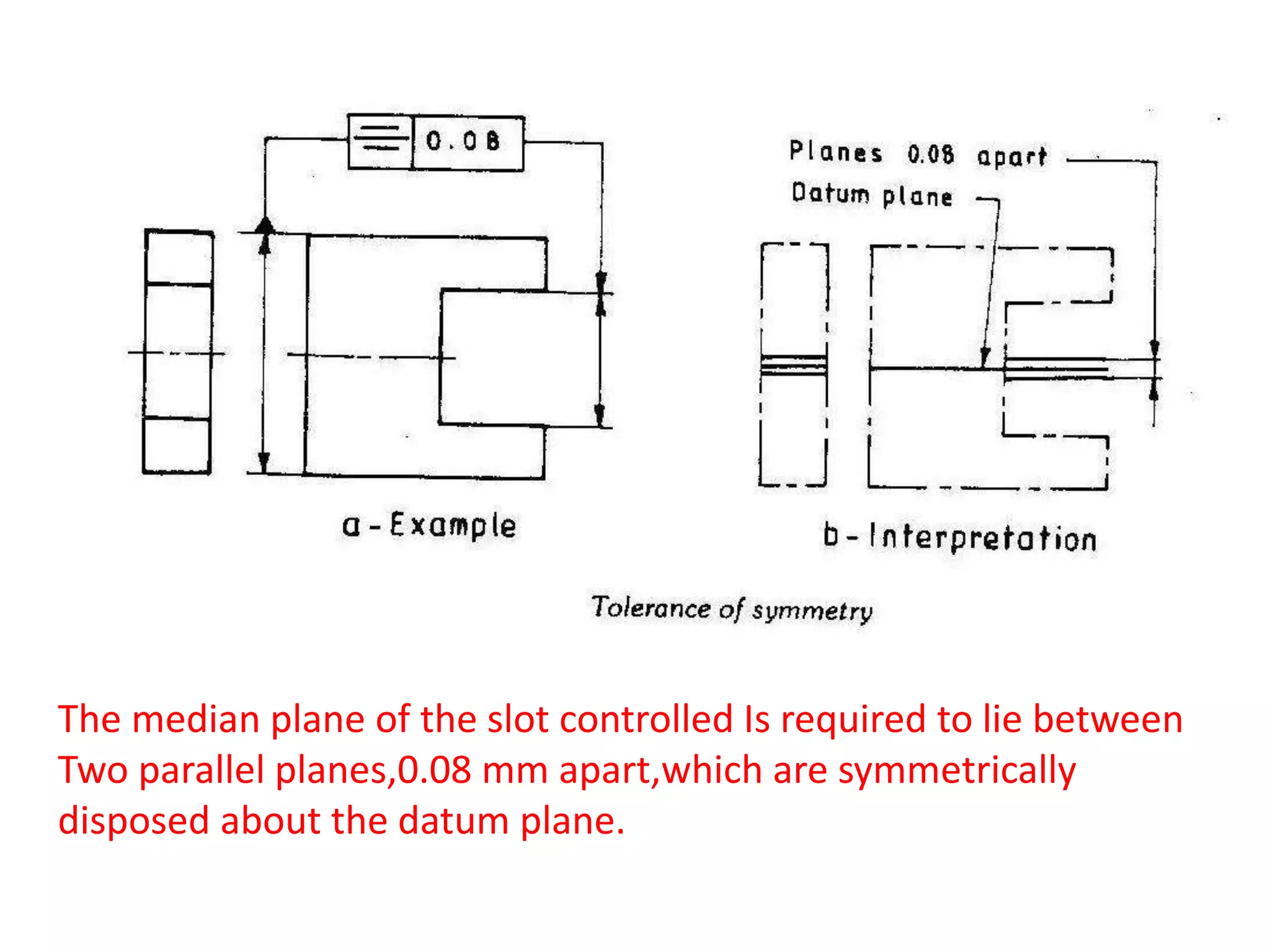
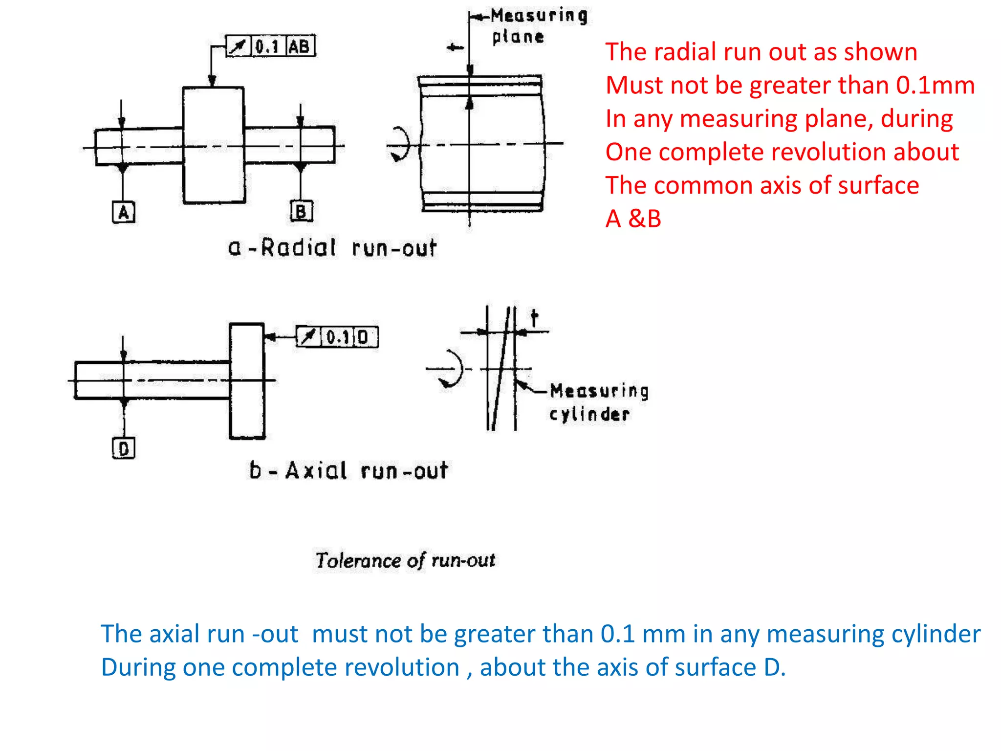
The line on the surface of the feature can take any
form ,provided it lies in an axial plane between two
parallel straight lines,0.02mm apart
The surface controlled as shown in Fig.can take
any form ,provided it lies in the space between
two flat parallel planes,0.04mm apart.
The circle controlled ,which may represent the periphery at
Any c /s, perpendicular to the axis can take any form
provided it lies in a space between two concentric circles
,0.03 mm radially apart.
The surface controlled may take any form provided it
lies between two perfect concentric Cylinders 0.03 mm
apart
The profile line controlled can take any form provided it lies
Between two lines 0.05 mm apart.
The curved surface of the part controlled is required to lie
between two surfaces 0.03 apart.
The controlled top surface of the part is required to lie between
two planes ,0.06 mm apart and Parallel to the datum line or surface.
The controlled end surface of the second component is Required
to lie between two planes ,0.06 mm apart and Perpendicular to
the axis of the left-side cylindrical portion (datum axis B).
The controlled inclined surfaces of the parts are to lie between
Two planes,0.1 mm apart which are inclined at 60°to the datum
Axis of the cylindrical portion or the datum surface.
The axis of the hole is required to be contained within a tolerance
Cylinder 0.08 mm diameter, centered on the specified true position
The axis of the right side cylindrical portion of the component is to
be contained within a cylinder 0.08 mm diameter and is to be co-
axial with the axis of the left side portion ,which is the datum.
The median plane of the slot controlled Is required to lie between
Two parallel planes,0.08 mm apart,which are symmetrically
disposed about the datum plane.
The radial run out as shown
Must not be greater than 0.1mm
In any measuring plane, during
One complete revolution about
The common axis of surface
A &B
The axial run -out must not be greater than 0.1 mm in any measuring cylinder
During one complete revolution , about the axis of surface D.

Geometrical tolerance 2014

  • 2.
    The line onthe surface of the feature can take any form ,provided it lies in an axial plane between two parallel straight lines,0.02mm apart
  • 3.
    The surface controlledas shown in Fig.can take any form ,provided it lies in the space between two flat parallel planes,0.04mm apart.
  • 4.
    The circle controlled,which may represent the periphery at Any c /s, perpendicular to the axis can take any form provided it lies in a space between two concentric circles ,0.03 mm radially apart.
  • 5.
    The surface controlledmay take any form provided it lies between two perfect concentric Cylinders 0.03 mm apart
  • 6.
    The profile linecontrolled can take any form provided it lies Between two lines 0.05 mm apart.
  • 7.
    The curved surfaceof the part controlled is required to lie between two surfaces 0.03 apart.
  • 8.
    The controlled topsurface of the part is required to lie between two planes ,0.06 mm apart and Parallel to the datum line or surface.
  • 9.
    The controlled endsurface of the second component is Required to lie between two planes ,0.06 mm apart and Perpendicular to the axis of the left-side cylindrical portion (datum axis B).
  • 10.
    The controlled inclinedsurfaces of the parts are to lie between Two planes,0.1 mm apart which are inclined at 60°to the datum Axis of the cylindrical portion or the datum surface.
  • 11.
    The axis ofthe hole is required to be contained within a tolerance Cylinder 0.08 mm diameter, centered on the specified true position
  • 12.
    The axis ofthe right side cylindrical portion of the component is to be contained within a cylinder 0.08 mm diameter and is to be co- axial with the axis of the left side portion ,which is the datum.
  • 13.
    The median planeof the slot controlled Is required to lie between Two parallel planes,0.08 mm apart,which are symmetrically disposed about the datum plane.
  • 14.
    The radial runout as shown Must not be greater than 0.1mm In any measuring plane, during One complete revolution about The common axis of surface A &B The axial run -out must not be greater than 0.1 mm in any measuring cylinder During one complete revolution , about the axis of surface D.