The document contains several assembly language programs for the 8085 microprocessor. The programs include:
1) A program to generate Fibonacci numbers that uses counters and registers to add and store successive numbers.
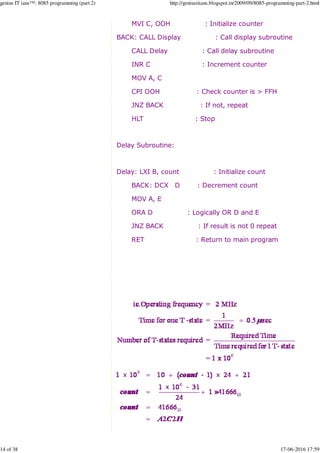
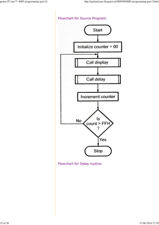
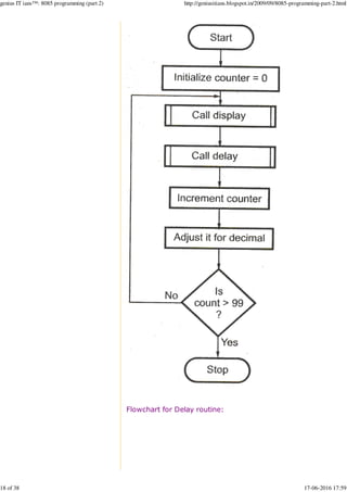
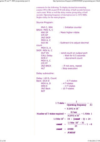
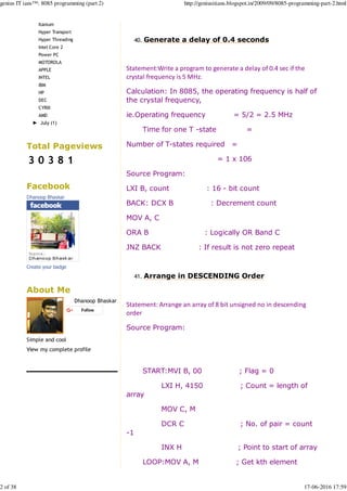
2) A program to generate a 0.4 second delay using an operating frequency of 2.5MHz and calculating the required number of T-states.
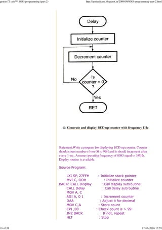
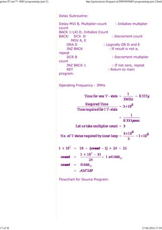
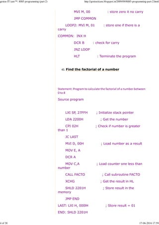
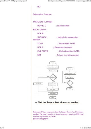
3) A program to find the factorial of a number between 0-8 using registers, a subroutine, and stack pointer to recursively multiply numbers.
![Saturday, September 26, 2009
8085 programming (part 2)
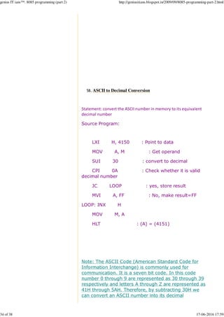
Program to generate fibonacci number39.
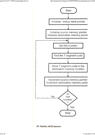
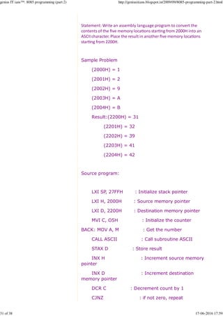
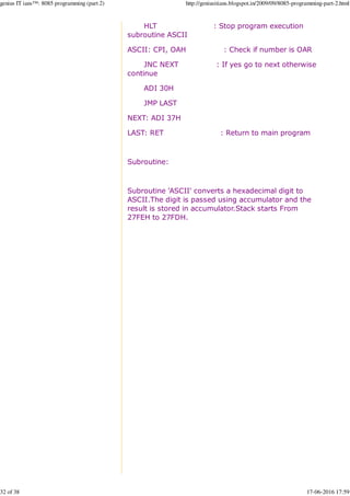
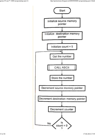
Statement:Write an assembly language program to generate
fibonacci number.
Source Program:
MVI D, COUNT : Initialize counter
MVI B, 00 : Initialize variable to store
previous number
MVI C, 01 : Initialize variable to store
current number
MOV A, B :[Add two numbers]
BACK: ADD C :[Add two numbers]
MOV B, C : Current number is now
previous number
MOV C, A : Save result as a new current
number
DCR D : Decrement count
JNZ BACK : if count 0 go to BACK
HLT : Stop.
Search
My Blogs
My Personal Blog
Mak IT possible
IT@UCET
Followers
with Google Friend Connect
Members (12)
Blog Archive
► 2010 (7)
▼ 2009 (22)
► November (2)
▼ September (19)
8085 programming (part4)
8085 programming (part3)
8085 programming (part 2)
8085 programming (part1)
Important microprocessors at a
glance
Xeon
0 More Next Blog» manojshahu07@gmail.com Dashboard Sign Out
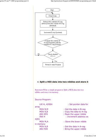
genius IT ians™
This blog is meant for helping B Tech students especially CSE and IT
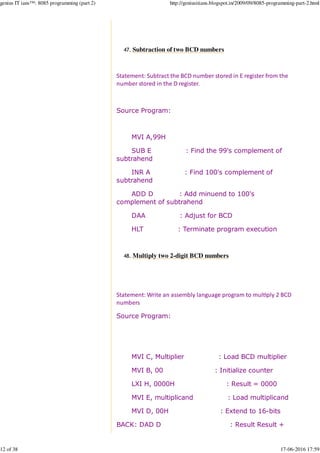
students. Its not created and manipulated by a professional; But by a
student like you. So there is chance of faults and defects. Please do
co-operate. Looking forward for your comments and suggestions... Let me
begin... Other blogs of mine: http://www.dhanoopbhaskar.in &
http://www.theinsanetechie.in
8085 (4) assembly language (4) DBMS (7)
microprocessors (19) PL/SQL (7) SQL (7)
genius IT ians™: 8085 programming (part 2) http://geniusitians.blogspot.in/2009/09/8085-programming-part-2.html
1 of 38 17-06-2016 17:59](https://image.slidesharecdn.com/geniusitians8085programmingpart2-160617152513/85/Genius-it-ians-8085-programming-part-2-1-320.jpg)
![Saturday, September 26, 2009
8085 programming (part 2)
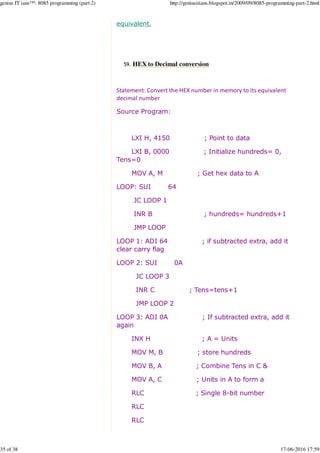
Program to generate fibonacci number39.
Statement:Write an assembly language program to generate
fibonacci number.
Source Program:
MVI D, COUNT : Initialize counter
MVI B, 00 : Initialize variable to store
previous number
MVI C, 01 : Initialize variable to store
current number
MOV A, B :[Add two numbers]
BACK: ADD C :[Add two numbers]
MOV B, C : Current number is now
previous number
MOV C, A : Save result as a new current
number
DCR D : Decrement count
JNZ BACK : if count 0 go to BACK
HLT : Stop.
Search
My Blogs
My Personal Blog
Mak IT possible
IT@UCET
Followers
with Google Friend Connect
Members (12)
Blog Archive
► 2010 (7)
▼ 2009 (22)
► November (2)
▼ September (19)
8085 programming (part4)
8085 programming (part3)
8085 programming (part 2)
8085 programming (part1)
Important microprocessors at a
glance
Xeon
0 More Next Blog» manojshahu07@gmail.com Dashboard Sign Out
genius IT ians™
This blog is meant for helping B Tech students especially CSE and IT
students. Its not created and manipulated by a professional; But by a
student like you. So there is chance of faults and defects. Please do
co-operate. Looking forward for your comments and suggestions... Let me
begin... Other blogs of mine: http://www.dhanoopbhaskar.in &
http://www.theinsanetechie.in
8085 (4) assembly language (4) DBMS (7)
microprocessors (19) PL/SQL (7) SQL (7)
genius IT ians™: 8085 programming (part 2) http://geniusitians.blogspot.in/2009/09/8085-programming-part-2.html
1 of 38 17-06-2016 17:59](https://image.slidesharecdn.com/geniusitians8085programmingpart2-160617152513/75/Genius-it-ians-8085-programming-part-2-1-2048.jpg)
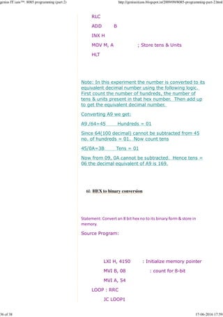
![Multiplicand
MOV A, L : Get the lower byte of
the result
ADI, 00H
DAA : Adjust the lower byte
of result to BCD.
MOV L, A : Store the lower byte of
result
MOV A, H : Get the higher byte of
the result
ACI, 00H
DAA : Adjust the higher byte
of the result to BCD
MOV H, A : Store the higher byte
of result.
MOV A, B : [Increment
ADI 01H : counter
DAA : adjust it to BCD and
MOV B,A : store it]
CMP C : Compare if count =
multiplier
JNZ BACK : if not equal repeat
HLT : Stop
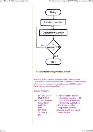
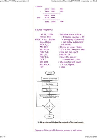
Generate and display binary up counter49.
Statement:Write a program for displaying binary up counter.
Counter should count numbers from 00 to FFH and it should
increment a2er every 0.5 sec.
Assume opera%ng frequency of 8085 equal to 2MHz. Display
rou%ne is available.
Source Program:
LXI SP, 27FFH : Initialize stack pointer
genius IT ians™: 8085 programming (part 2) http://geniusitians.blogspot.in/2009/09/8085-programming-part-2.html
13 of 38 17-06-2016 17:59](https://image.slidesharecdn.com/geniusitians8085programmingpart2-160617152513/85/Genius-it-ians-8085-programming-part-2-13-320.jpg)