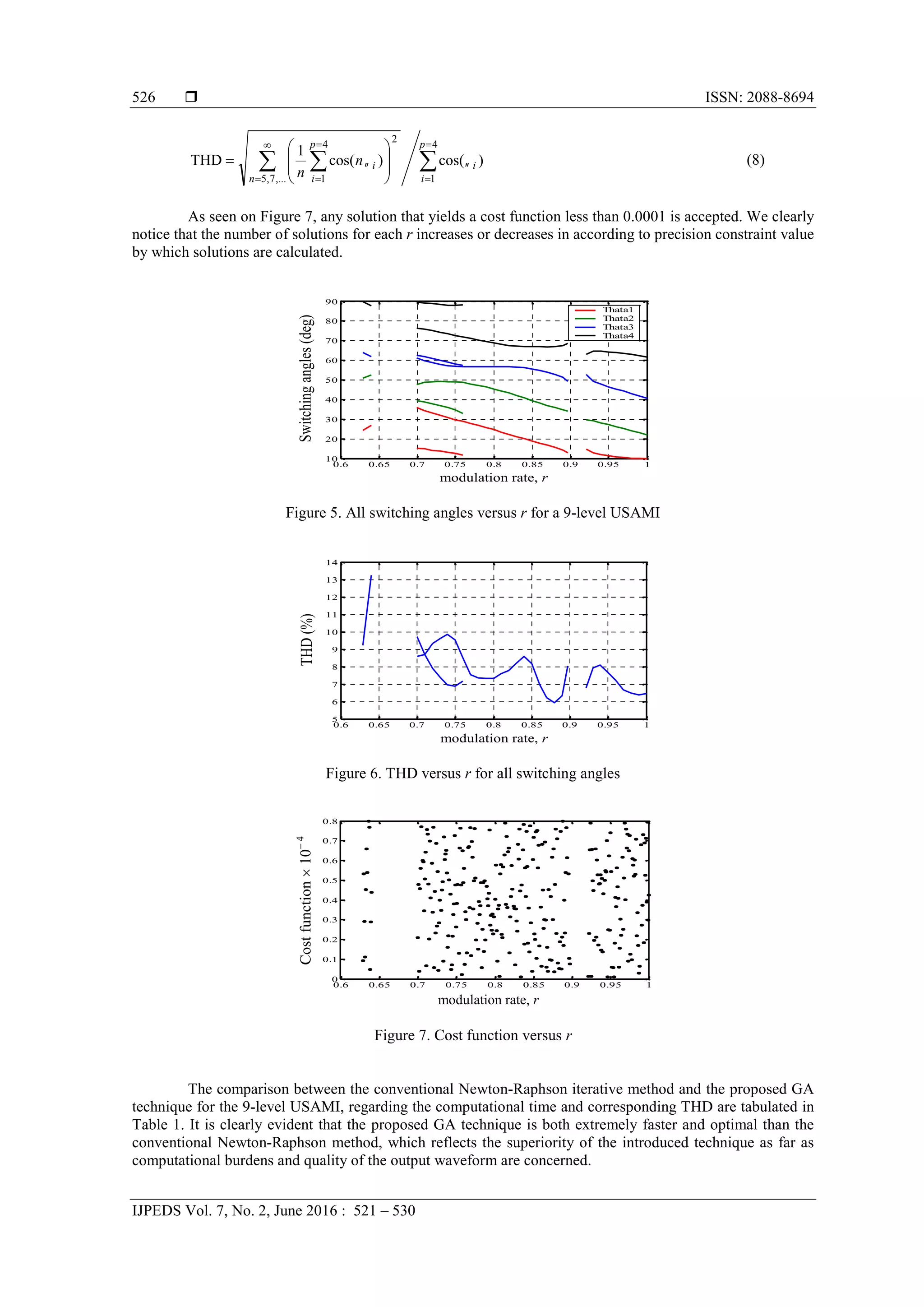
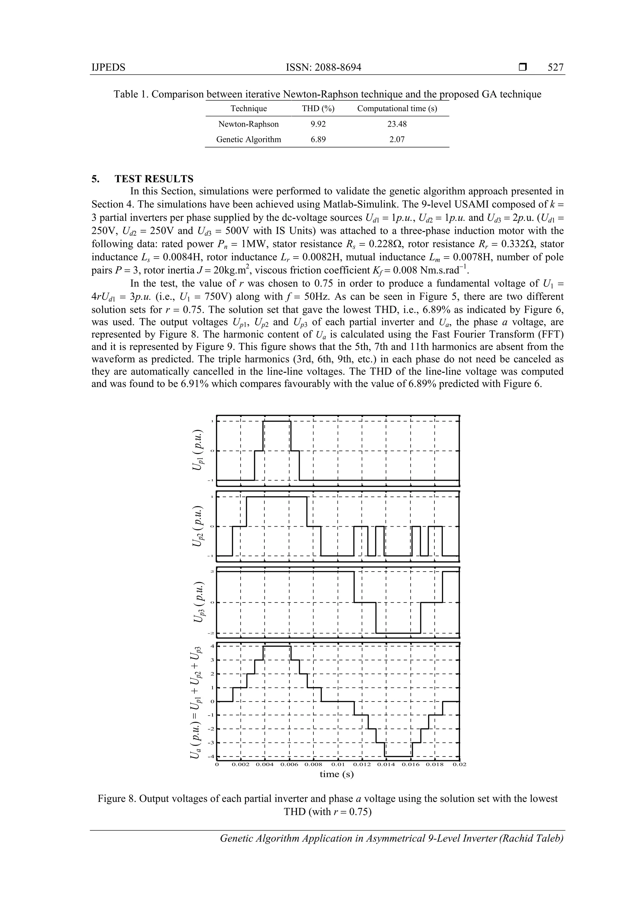
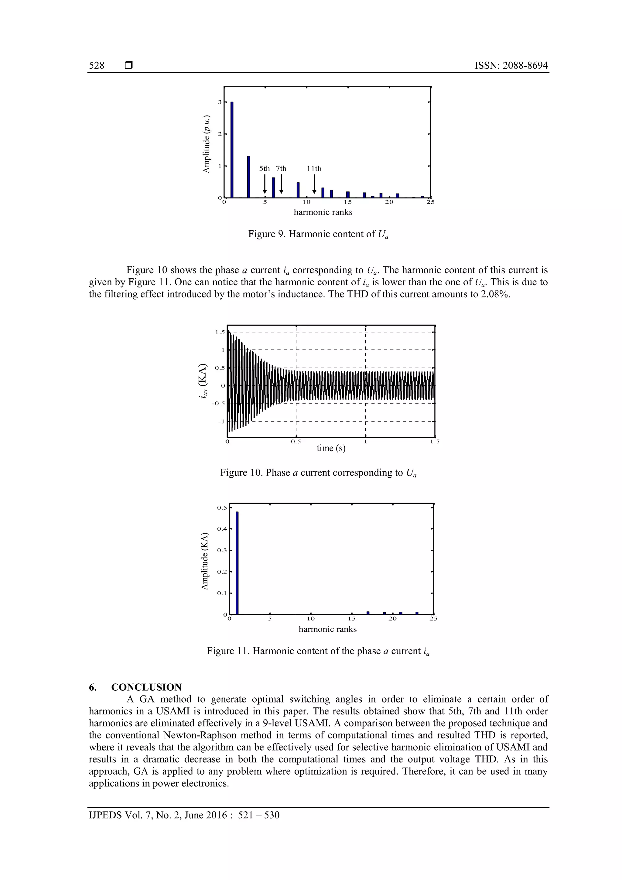
This paper discusses the application of a genetic algorithm for selective harmonic elimination in a 9-level asymmetrical multilevel inverter to optimize switching angles and eliminate specific harmonics while maintaining fundamental voltage. The approach is presented as a simpler alternative to traditional methods, addressing the complexities of solving non-linear equations in multilevel inverter design. The findings demonstrate improved effectiveness in achieving lower total harmonic distortion through the proposed genetic algorithm technique.
![International Journal of Power Electronics and Drive System (IJPEDS)
Vol. 7, No. 2, June 2016, pp. 521~530
ISSN: 2088-8694 521
Journal homepage: http://iaesjournal.com/online/index.php/IJPEDS
Genetic Algorithm Application in Asymmetrical 9-Level
Inverter
Rachid Taleb, M’hamed Helaimi, Djilali Benyoucef, Zinelaabidine Boudjema
Electrical Engineering Department, Hassiba Benbouali University, Chlef, Algeria
Laboratoire Génie Electrique et Energies Renouvelables (LGEER)
Article Info ABSTRACT
Article history:
Received Aug 13, 2015
Revised Mar 15, 2016
Accepted Apr 1, 2016
Selective harmonic elimination (SHE) has been a widely researched
alternative to traditional PWM techniques. This paper presents the selective
harmonic elimination of a uniform step asymmetrical multilevel inverter
(USAMI) using genetic algorithm (GA) which eliminates specified higher
order harmonics while maintaining the required fundamental voltage. This
technique can be applied to USAMI with any number of levels. As an
example, in this paper a 9-level USAMI is considered and the optimum
switching angles are calculated to eliminate the 5th, 7th and 11th harmonics.Keyword:
Asymmetrical 9-level inverter
Genetic algorithm
Optimum switching angles
Selective harmonic elimination
Copyright © 2016 Institute of Advanced Engineering and Science.
All rights reserved.
Corresponding Author:
Rachid Taleb,
Electrical Engineering Department,
Hassiba Benbouali University,
Laboratoire Génie Electrique et Energies Renouvelables (LGEER),
Hay Salem, Route Nationale No 19, Chlef, Algeria.
Email: r.taleb@univ-chlef.dz
1. INTRODUCTION
Multilevel inverters have been widely used in last years for high-power applications [1]. Variable-
speed drives have reached a wide range of standard applications such as pumps, fans and others. Many of
these applications use medium-voltage motors (2300, 3300, 4160 or 6600V), due to their lower current
ratings in higher power levels [2]. Static Var compensators and active filters are other applications that use
multilevel converters [3].
Several topologies of multilevel inverters have been studied and presented. Among them, neutral
point clamped inverters [4], flying capacitors inverters also called imbricated cells [5], and series connected
cells inverters also called cascaded inverters [6]. The industry often has used the neutral-point-clamped
inverter [7]. However, the topology that uses series connected cells inverters presents some advantages, as
smaller voltage rate (dU/dt) due to existence of higher number levels, producing less common-mode voltage
across motor windings [8]. Furthermore, this topology is simple and its modular configuration makes it easily
extensible for any number of desired output voltage levels. Figure 1a shows the basic diagram of this
topology with k partial cells represented by Figure 1b. The jth
single-phase inverter is supplied by a dc-
voltage source Udj (j 1…k). The relationship between the number of series-connected single-phase inverters
in each phase and the number of output voltage levels generated by this topology, respectively k and N, is
given by: N 2k 1, in the case where there are equal voltages in all partial inverters.
In all the well-known multilevel converter topologies, the number of power devices required
depends on the output voltage level needed [9]. However, increasing the number of power semiconductor
switches also increases the converter circuit and control complexity and the costs. To provide a large number](https://image.slidesharecdn.com/2415mar169dec8802rachidtalebijpeds-171219011825/75/Genetic-Algorithm-Application-in-Asymmetrical-9-Level-Inverter-1-2048.jpg)
![ ISSN: 2088-8694
IJPEDS Vol. 7, No. 2, June 2016 : 521 – 530
522
of output levels without increasing the number of converters, a uniform step asymmetrical multilevel
inverters (USAMI) can be used [10].
Figure 1. a) A series-connected multilevel inverter topology with k partial cells, b) Partial cell configuration
The key issue in designing an effective multilevel inverter is to ensure that the Total Harmonic
Distortion (THD) of the output voltage waveform is within acceptable limits. Selective harmonic elimination
(SHE) has been intensively studied in order to achieve low THD [11, 12]. The output voltage waveform
analysis using Fourier theory produces a set of non-linear transcendental equations. The solution of these
equations, if exists, gives the switching angles required for certain fundamental component and selected
harmonic profile. Iterative procedures such as Newton-Raphson method has been used to solve these sets of
equations [13]. This method is derivative-dependent and may end in local optima, and a judicious choice of
the initial values alone guarantees conversion [14]. Another approach based on converting the transcendental
equation into polynomial equations is presented in [15], where resultant theory is applied to determine the
switching angles to eliminate specific harmonics. That approach, however, appears to be unattractive because
as the number of inverter levels increases, so does the degree of the polynomials of the mathematical model.
This is likely to lead to numerical difficulty and substantial computational burden as well.
In this paper, a general genetic algorithm approach will be presented, which solves the same
problem with a simpler formulation and with any number of levels without extensive derivation of analytical
expressions. GA is a search method to find the maximum of functions by mimicking the biological
evolutionary processes. There are only a few examples of GA applications for power electronics in the
literature [16-19], but none on GA applied to USAMI. This approach is compared to the conventional
Newton-Raphson method, where the superiority of the presented algorithm is reported.
2. UNIFORM STEP ASYMMETRICAL MULTILEVEL INVERTER
Multilevel inverters generate at the ac-terminal several voltage levels as close as possible to the
input signal. Figure 2 for example illustrates the N voltage levels Us1, Us2, ... UsN composing a typical
sinusoidal output voltage waveform. The output voltage step is defined by the difference between two
consecutive voltages. A multilevel converter has a uniform or regular voltage step, if the steps ∆U between
all voltage levels are equal. In this case the step is equal to the smallest dc-voltage, Ud1 [10]. This can be
expressed by
NlUUUU dlssl 2,1)1( (1)
If this is not the case, the converter is called a non uniform step AMI or irregular AMI. An USAMI
is based on dc-voltage sources to supply the partial cells (inverters) composing its topology which respects to
the following conditions:
1
1
21
21
...
j
l
dldj
dkdd
UU
UUU
(2)
Ud1
Ud2
Udk
Us
a)
Upj
Udj
b)](https://image.slidesharecdn.com/2415mar169dec8802rachidtalebijpeds-171219011825/75/Genetic-Algorithm-Application-in-Asymmetrical-9-Level-Inverter-2-2048.jpg)
![IJPEDS ISSN: 2088-8694
Genetic Algorithm Application in Asymmetrical 9-Level Inverter (Rachid Taleb)
523
where k represents the number of partial cells per phase and j 1…k. The number of levels of the output
voltage can be deduced from
k
j d
dj
U
U
N
1 1
21 (3)
This relationship fundamentally modifies the number of levels generated by the multilevel topology.
Indeed, the value of N depends on the number of cells per phase and the corresponding supplying dc-
voltages.
Figure 2. Typical output voltage waveform of a multilevel inverter
Equation (3) accepts different solutions. With k 3 for example, there are two possible
combinations of supply voltages for the partial inverters in order to generate a 13-level global output, i.e.,
(Ud1, Ud2, Ud3) (1, 1, 4), (1, 2, 3), and there are three possible combinations to generate a 15-level global
output, i.e., (Ud1, Ud2, Ud3) (1, 1, 5), (1, 2, 4), (1, 3, 3). Figure 3 shows the possible output voltages of the
three partial cells of the 9-level inverter with k 3. The dc-voltages of the three cells are Ud1 1p.u., Ud2
1p.u. and Ud3 2p.u.. The output voltages of each partial inverter are noted Up1, Up2 and Up3 and can take
three different values: Up1 -1, 0, 1, Up2 -1, 0, 1 and Up3 -2, 0, 2. The result is a generated output
voltage with 9-levels: Us -4, -3, -2, -1, 0, 1, 2, 3, 4. Some levels of the output voltage can be generated
by different commutation sequences. For example, there are four possible commutation sequences resulting
in Us 2p.u.: (Up1, Up2, Up3) (-1, 1, 2), (0, 0, 2), (1, -1, 2), (1, 1, 0). These redundant combinations can
be selected in order to optimize the switching process of the inverter [20].
These different possibilities offered by the output voltage of the partial inverters, and the
redundancies among them to deliver a same output voltage level, can be considered as degrees of freedom
which can be exploited in order to optimize the use of a USAMI.
Figure 3. Possible output voltages of each partial inverter to generate N 9 levels with k 3 cells per phase
(Ud1 1p.u., Ud2 1p.u. and Ud3 2p.u.)
UsN
Us(N-1)
θ1 θ2 θp
π/2
π 2π
3π/2
Us
Us1
Us2
…
…
..…
(0)1 2 3
Parcial cells
Us=Up1+Up2+Up3
Up2 + Up3
Up3
Up24
3
2
1
0
-1
-2
-3
-4](https://image.slidesharecdn.com/2415mar169dec8802rachidtalebijpeds-171219011825/75/Genetic-Algorithm-Application-in-Asymmetrical-9-Level-Inverter-3-2048.jpg)
![ ISSN: 2088-8694
IJPEDS Vol. 7, No. 2, June 2016 : 521 – 530
524
3. MODULATION CONTROL
Generally, traditional PWM control methods and space vector PWM methods are applied to
symmetrical multilevel inverter modulation control [21-24], and can also be used to control asymmetrical
multilevel inverter. These methods will cause extra losses due to high switching frequencies. For this reason,
low-switching frequency control methods, such as selective harmonic elimination, represent interesting and
alternative solutions [15, 25].
The SHE is based on the Fourier analysis of the generated voltage Us at the output of the USAMI
(Figure 2). This voltage is symmetric in a half and a quarter of a period. As a result, the even harmonic
components are null. The Fourier series expansion for the Us voltage is thus:
p
i
i
d
n
n
ns n
n
U
UtnUU
1
1
1
)cos(
4
with,)sin(
(4)
where Un is the amplitude of the harmonic term of rank n, p (N 1)/2 is the number of switching angles per
quarter waveform, and i is the ith
switching angle.
The p switching angles in (4) are calculated by fixing the amplitude of the fundamental term and by
canceling the p 1 other harmonic terms. Practically, four switching angles (1, 2, 3, 4) are necessary for
canceling the three first harmonics terms (i.e., harmonics with a odd rank and non multiple of 3, therefore 5,
7 and 11) in the case of a three phase 9-level USAMI composed of k 3 partial inverters per phase supplied
by the dc-voltages Ud1 1p.u., Ud2 1p.u. and Ud3 2p.u.. These switching angles can be determined by
solving the following system of non linear equations:
4
1
4
1
11,7,5for0)cos(
)cos(
p
i
i
p
i
i
nn
r
(5)
where r U1/4Ud1 is the modulation rate. The solution of (5) must also satisfy
2
0 4321
(6)
An objective function is then needed for the optimization procedure, which is selected as a measure
of effectiveness of eliminating selected order of harmonics while maintaining the fundamental component at
a pre-specified value. Therefore, this objective function is defined as:
11,7,5
2
2
4
1
4321 )cos(),,,()(
i
i
p
i
i UrFF (7)
The optimal switching angles are obtained by minimizing equation (7) subject to the constraint (6),
and consequently the required harmonic profile is achieved. The main challenge is the non-linearity of the
transcendental set of equation (5), as most iterative techniques suffer from convergence problems and other
techniques such as elimination using resultant theory [15] and Walsh function [26] are complicated. It is,
therefore, worth considering more techniques and simple techniques such as GA.
4. SOLUTION USING GA
GA is a search mechanism imitates the natural selection and the genetics of living organisms. A
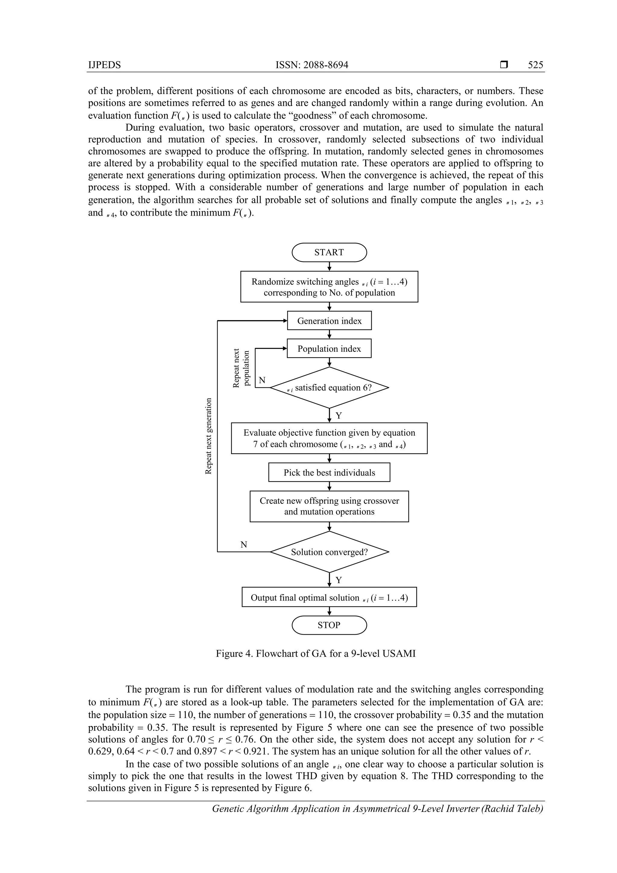
typical GA consists of three operators, i.e., reproduction, crossover, and mutation [27]. A flowchart of the
GA algorithm is shown in Figure 4.
The process of a GA usually begins with a randomly selected population of chromosomes. These
chromosomes are representations of the problem to be solved, in this case switching angles 1, 2, 3 and 4
of a 9-level USAMI. Then to start the search procedure, the switching angles are randomly generated. These
values must be satisfied the conditions of (6) for the chosen number of population. According to the attributes](https://image.slidesharecdn.com/2415mar169dec8802rachidtalebijpeds-171219011825/75/Genetic-Algorithm-Application-in-Asymmetrical-9-Level-Inverter-4-2048.jpg)
![IJPEDS ISSN: 2088-8694
Genetic Algorithm Application in Asymmetrical 9-Level Inverter (Rachid Taleb)
529
REFERENCES
[1] J. Rodriguez, J.S. Lai, F.Z. Peng, "Multilevel inverters: a survey of topologies, control and applications", IEEE
Transaction on Power Electronics, vol. 49, no. 4, pp. 724-738, August 2002.
[2] G. Baoming, F.Z. Peng, A.T. de Almeida, H. Abu-Rub, "An Effective Control Technique for Medium-Voltage
High-Power Induction Motor Fed by Cascaded Neutral-Point-Clamped Inverter", IEEE Transactions on Industrial
Electronics, vol. 57, no. 8, pp. 2659-2668, August 2010.
[3] H. Kojima, K. Matsui, K. Tsuboi, "Static Var compensator having active filter function for lower order harmonics",
IEEE Conference on Industrial Electronics Society, IECON’04, vol. 2, pp. 1133-1138, November 2004.
[4] J. Rodriguez, S. Bernet, P.K. Steimer, I.E. Lizama, "A Survey on Neutral-Point-Clamped Inverters", IEEE
Transactions on Industrial Electronics, vol. 57, no. 7, pp. 2219-2230, July 2010.
[5] J. Huang, K.A. Corzine, "Extended operation of flying capacitor multilevel inverters", IEEE Transactions on
Power Electronics, vol. 21, no. 1, pp. 140-147, January 2006.
[6] E. Babaei, "A cascade Multilevel Converter Topology With Reduced Number of Switches", IEEE Transactions on
Power Electronics, vol. 23, no. 6, pp. 2657-2664, November 2008.
[7] S. Kouro, M. Malinowski, K. Gopakumar, J. Pou, L.G. Franquelo, B. Wu, J. Rodriguez, M.A. Pérez, J.I. Leon,
"Recent Advances and Industrial Applications of Multilevel Converters", IEEE Transactions on Industrial
Electronics, vol. 57, no. 8, pp. 2553-2580, August 2010.
[8] L.M. Tolbert, F.Z. Peng, T.G. Habetler, "Multilevel converters for large electric drives", IEEE Transactions on
Industry Applications, vol. 35, no. 1, pp. 36-44, January-February 1999.
[9] J. Rodriguez, L.G. Franquelo, S. Kouro, J.I. Leon, R.C. Portillo, M.M. Prats, M.A. Pérez, "Multilevel Converters :
An Enabling Technology for High-Power Applications", Proceedings of the IEEE, vol. 97, no. 11, pp. 1786-1817,
November 2009.
[10] J. Song-Manguelle, S. Mariethoz, M. Veenstra, A. Rufer, "A Generalized Design Principle of a Uniform Step
Asymmetrical Multilevel Converter for High Power Conversion", European Conference on Power Electronics and
Applications, EPE’01, Graz, Austria, August 2001.
[11] M.S.A. Dahidah, V.G. Agelidis, "Selective Harmonic Elimination PWM Control for Cascaded Multilevel Voltage
Source Converters: A Generalized Formula", IEEE Transaction on Power Electronics, vol. 23, no. 4, pp. 1620-
1630, July 2008.
[12] A. Hiendro, "Multiple Switching Patterns for SHEPWM Inverters Using Differential Evolution Algorithms",
International Journal of Power Electronics and Drive System (IJPEDS), vol. 1, no. 2, pp. 94-103, December 2011.
[13] T. Cunnyngham, "Cascade multilevel inverters for large hybrid-electric vehicle applications with variant dc
sources", Master thesis, University of Tennessee, Knoxville, 2001.
[14] J. Kumar, B. Das, P. Agarwal, "Selective Harmonic Elimination Technique for a Multilevel Inverter", Fifteenth
National Power Systems Conference, NPSC’08, IIT Bombay, pp. 608-613, December 2008.
[15] R. Taleb, A. Derrouazin, "USAMI Control with a Higher Order Harmonics Elimination Strategy based on the
Resultant Theory", Energy Procedia, Elsevier Ltd, vol. 50, pp. 1045-1055, 2014.
[16] V. Jegathesan, "Genetic algorithm based solution in PWM converter switching for voltage source inverter feeding
an induction motor drive", AJSTD, vol. 26, no. 2, pp. 45-60, 2010.
[17] N. Tutkun, "Improved power quality in a single-phase PWM inverter voltage with bipolar notches through the
hybrid genetic algorithms", Expert Systems with Applications, Elsevier Ltd, vol. 37, no. 8, pp. 5614-5620, August
2010.
[18] A.R. Firdaus, A.S. Rahman, "Genetic Algorithm of Sliding Mode Control Design for Manipulator Robot",
Telkomnika, vol. 10, no. 4, pp. 645-654, December 2012.
[19] F. Tahami, H. Nademi, M. Rezaei, "Maximum Torque per Ampere Control of Permanent Magnet Synchronous
Motor Using Genetic Algorithm", Telkomnika, vol. 9, no. 2, pp. 237-244, August 2011.
[20] M. Veenstra, "Investigation and Control of a Hybrid Asymmetrical Multi-level Inverter for Medium-Voltage
Applications", Ph.D. thesis, EPF-Lausanne, Switzerland, 2003.
[21] Z.B. Ibrahim, M.L. Hossain, I.B. Bugis, J.M. Lazi, N.M. Yaakop, "Comparative Analysis of PWM Techniques for
Three Level Diode Clamped Voltage Source Inverter", International Journal of Power Electronics and Drive
System (IJPEDS), vol. 5, no. 1, pp. 15-23, 2014.
[22] R. Taleb, D. Benyoucef, M. Helaimi, Z. Boudjema, H. Saidi, "Cascaded H-bridge Asymmetrical Seven-level
Inverter Using THIPWM for High Power Induction Motor", International Conference on Technologies and
Materials for Renewable Energy, Environment and Sustainability, TMREES’15, Beirut, Lebanon, 17-20 April,
2015.
[23] C. Gomathi, N. Nagath, S. Veerakumar, "Sampled Reference Frame Algorithm Based on Space Vector Pulse Width
Modulation for Five Level Cascaded H-Bridge Inverter", Buletin Teknik Elektro dan Informatika, vol. 3, no. 2, pp.
127-140, June 2014.
[24] M. Yaichi, M.K. Fellah, "An Implementation Mechanisms of SVM Control Strategies Applied to Five Levels
Cascaded Multi-Level Inverters", International Journal of Power Electronics and Drive System (IJPEDS), vol. 4,
no. 2, pp. 146-155, June 2014.
[25] P. Avirajamanjula, P. Palanivel, "Corroboration of Normalized Least Mean Square Based Adaptive Selective
Current Harmonic Elimination in Voltage Source Inverter using DSP Processor", International Journal of Power
Electronics and Drive System (IJPEDS), vol. 6, no. 1, pp. 178-184, 2015.
[26] T.J. Liang, R.M. O’Connnell, R.G. Hoft, "Inverter harmonic reduction using Walsh function harmonic elimination
method", IEEE Transactions on Industrial Electronics, vol. 12, no. 6, pp. 971-982, November 1997.](https://image.slidesharecdn.com/2415mar169dec8802rachidtalebijpeds-171219011825/75/Genetic-Algorithm-Application-in-Asymmetrical-9-Level-Inverter-9-2048.jpg)
![ ISSN: 2088-8694
IJPEDS Vol. 7, No. 2, June 2016 : 521 – 530
530
[27] C.R. Reeves, J.E. Rowe, "Genetic Algorithms: Principles and Perspectives-A Guide to GA Theory", Kluwer
Academic Publishers, New York, Boston, Dordrecht, London, Moscow, 2002.
BIOGRAPHIES OF AUTHORS
Rachid Taleb was born in Chlef, Algeria, in 1974. He received the M.S. degree in electrical
engineering from the Hassiba Benbouali University, Chlef, Algeria, in 2004 and the Ph.D.
degree in electrical engineering from the Djillali Liabes University, Sidi Bel-Abbes, Algeria, in
2011. He is currently an Associate Professor at the Department of Electrical Engineering,
Hassiba Benbouali University. He is a team leader in the LGEER Laboratory (Laboratoire Génie
Electrique et Energies Renouvelables). His research interest includes intelligent control, heuristic
optimization, control theory of converters and converters for renewable energy sources.
M’hamed Helaimi was born in Chlef, Algeria, in 1976. He received the Engineer Degree (with
honors) and the Magister Degree, in Electrical Engineering from the University of Chlef,
Algeria, in 2001 and 2004, respectively. In 2004, He joined the Department of Electrical
Engineering, University of Chlef, where, from 2004 to 2014, He was a research assistant. He
received the Ph.D. degree in Electrical Engineering from the University of Sciences and
technology of Oran, Algeria, in 2014. He is Researcher member in the Laboratory of Electrical
Engineering and Renewable Energy since 2011. His scientific work is related to induction
heating application and drives, Genetic Algorithm, Artificial intelligence, non linear control,
dynamic modeling, DSP processor, FPGA and Power Electronics.
Djilali Benyoucef was born in Ain Defla, Algeria, in 1975. He received the Ph.D. degree in
physics and engineering of plasmas discharge from Paul Sabatier University, Toulouse, France,
in 2011, and the another Ph.D. degree in high voltage and electrical discharges from USO-TMB
University of Oran, Algeria. He is Teacher and Researcher with the University of Chlef, Algeria,
and the Laboratory of Electrical Engineering and Renewable Energy since 2002. He has also
been with the LAPLACE Laboratory, Paul Sabatier University, since 2007. His current research
interests include modeling of non thermal plasmas and low-pressure electrical discharges and
their applications. He is the author and reviewer of several international publications. Recently,
he works in the domain of identification and control of system.
Zinelaabidine Boudjema was born in Algeria, in 1983. He received the M.S. degree in
Electrical Engineering from ENPO, Oran, Algeria, in 2010, and the PhD degree in Electrical
Engineering from Djillali liabes University, Sidi Bel abbes, Algeria, in 2015. He is currently an
Associate Professor at Electrical Engineering Department at Hassiba Benbouali University. His
research interests include power electronics, electrical machine robust control and renewable
energies.](https://image.slidesharecdn.com/2415mar169dec8802rachidtalebijpeds-171219011825/75/Genetic-Algorithm-Application-in-Asymmetrical-9-Level-Inverter-10-2048.jpg)