
Recommended
Recommended
More Related Content
Similar to Week-High voltage engineering presentstion
Similar to Week-High voltage engineering presentstion (20)
Recently uploaded
Recently uploaded (20)
Week-High voltage engineering presentstion
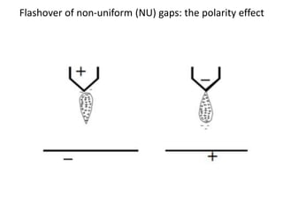
- 1. Flashover of non-uniform (NU) gaps: the polarity effect
- 2. V-I characteristics of electrical discharge • V-I graph is strictly valid for DC discharges in gas discharge tubes • however, similar phenomenon occur in case of AC flashover in air • not realizable in one single setup • explains different stages of discharge with I ranging from nA to kA
- 3. V-I characteristics of electrical discharge • electrons from cosmic radiation accelerate & cause ionization • electron avalanche—>secondary emission—> Townsend discharges • space charge effect is initially negligible • with increasing current, space charge becomes important • space charge sheaths formed & transition to glow occurs
- 4. V-I characteristics of electrical discharge • glow transition is often referred as ‘breakdown’ • With increase in current, transition from a normal glow to an abnormal glow occurs • plasma heating & transition to an arc discharge occurs • Arc is marked by -ve resistance region (low V and high I)
- 5. Corona discharges • In uniform gaps, V at which ionisation starts = BDV (3 kV/mm for air) • in non uniform gaps, the Emax occurs near electrodes of smaller ‘r’; ionization threshold gets exceeded only in these areas • Partial discharge or ‘corona’ occurs thereafter • Corona is a self- sustaining discharge (f = 20 Hz to 20 kHz) • it is visible as bluish/violet colour and audible with a hissing noise
- 6. Corona discharges • Corona is a luminous discharge formed due to ionization of the air surrounding an electrode, caused by a voltage gradient exceeding a certain critical value. • These discharges generate light, audible noise, radio noise, and energy loss among other things. • undesirable effects of corona ‣ pre-cursor to flashover ‣ radio interference ‣ additional power loss ‣ insulation degradation due to UV radiation from corona
- 7. Corona discharges More details A variety of forms of corona discharge, from various metal objects. Notice, especially in the last two pictures, how the discharge is concentrated at the points on the objects.
- 8. Corona on cylindrical conductors a : 2cm, b: 12 cm, V: 150 kV - gap between conductors: 10 cm - avg. E: 15 kV/cm - actual field variation Ea is field strength exceeds 30 kV/cm in the shaded region - In this region the air gets ionized - partial breakdown or corona starts
- 9. Peek’s empirical equation for visible corona onset at the surface of the HV conductor in coaxial cylinders: E =E0mδ(1+K (δ.a)−s) kV/cm where E0 = 30 (units: kV/cm) m = surface roughness factor (0.7 to 1) a = radius of the inner conductor K and s are constants (K=0.3, s=0.5) and δ is air density factor given by where, p: ambient pressure p0: normal pressure (1 bar) t: ambient temperature t0: normal temperature (20°C) Corona at sharp points A sharp point can be modelled as a small sphere (radius a) If ground is very far from the sharp point, then Esharp point = V/a
- 10. Problems caused by corona Corona in air appears as bluish luminous discharge with ozone formation Corona Interference (Radio Interference Voltage, RIV): - Corona current pulses produce magnetic and electrostatic fields - the fields in turn induce high frequency voltage pulses in nearby radio antennas (Radio interference in the range 0.2 to 10 MHz) Corona Losses: - Corona current causes power loss on the line - During rain, corona forms on droplets on the conductor - losses of tens of MW can occur on a 500 kV line
- 11. Measures to curb Corona Corona is caused by field intensification at sharp points (small r) - Sharp edges and points on HV hardware must be avoided - For EHV lines bundled conductors (4 per phase) are used - On the 800 kV lines (UHV) 6 or 8 conductors are used - bundle conductors result in large radius thus minimizing losses - Grading rings fitted at insulator-Line joints reduces corona
- 12. Measures to curb Corona
- 13. Breakdown in Vacuum as Electrical Insulator Conductive matter that enables breakdown in vacuum insulation can come from several sources • Semi-conductive surface oxides from the inner surfaces of the vacuum chamber • Impurity concentrations, such as, adsorbates, dust • Organic vapours from, e.g., grease and rubber O-rings The breakdown strength of vacuum depends strongly upon the magnitude of pressure.
- 14. Breakdown characteristics with ac power frequency voltage, measured at different pressures for an electrode system with weakly non-uniform field
- 15. Generation of High Voltages (AC)in lab - HVAC is generated in lab for insulation testing purpose - primary source of power is at 230 V (120 V), 50 Hz (60 Hz) - load impedances involved are in Mega ohm range and currents < 1 A - hence, High Voltage testing need not require high power ratings
- 16. Methods to generate high AC voltages are: • Cascade transformers (power freq) • Resonant transformer (power freq) • Resonant transformer (high freq: Tesla Coil) Generation of High Voltages (AC)in lab
- 17. Cascade Transformers - for V < 400kV, a single transformer can be used for testing - for voltage > 400 kV, single transformer is usually avoided ‣ insulation problems ‣ expensive ‣ Transportation and assembly become difficult - Cascade or series connection of transformers is a better choice
- 18. Cascade Transformers • 2 or 3 identical transformers in cascade • secondary HV windings in series
- 20. - Each transformer has LV, HV and tertiary or excitation windings - tank of 1st transformer, T1, is at ground potential ‣ Excitation winding of T1 is connected to LV winding of T2 ‣ Ratings of Exc.winding (prev T) and LV winding (next T) are similar ‣ HV winding and excitation winding are taken through a bushing Circuit configuration
- 21. Circuit configuration - HV of T1 and secondary of T2 connected to tank of T2 - Tank potential of T2 is V and hence, it is kept on an insulator - HV of T2 and secondary of T3 connected to tank of T3 - Tank potential of T3 is 2V and kept on a much higher insulator - All three HV windings are in series - The output Voltage at T3 secondary is 3V w.r.t. ground
- 22. If P is the rated KVA of the cascade set, then P = 3VI each of the HV windings will thus carry a current of, I = P/3V Each of the secondary windings carry 1/3rd power i.e. P/3 Load distribution in Cascade Transformer
- 23. - Primary of T3 is loaded with P/3 —>supplied by exc winding of T2 - Next, primary of T2 supplies 2/3rd P (P/3 of sec + P/3 of exc) - Finally, primary of T1 supplies full power P - i.e. heavy loading of primary and excitation windings for lower stages; a factor to be considered in designing the cascade set - Load distribution in Cascade Transformer
- 24. ( R) x Mea su r ed volt a ge a t T1 - o/p voltage at T3 = Cascade ratio secondary (kV) - In the three stage transformer case discussed, R=3 (practically, slightly >3) - Usually, load that comes on cascade set is capacitive - for capacitive load, full load voltage > no-load voltage - for a cascade set, this “loading effect” will be more Output Voltage of Cascade Transformer: ratio effect Unity PF Lag Lead
- 25. Advantages and Disadvantages of Cascade Transformer • Disadvantage - Expensive and requires more space • Advantages - Natural cooling is sufficient - The transformers are light and compact - Transportation and assembly is easy - Construction is identical for individual units
- 26. High Voltage Lab, IISc Each transformer is rated at 50 Hz, 2.3 kV/350 kV Secondary of each transformer has a measurement winding (1:1000) An alternator (1 MVA, 2.3 kV) feeds primary of first transformer 1963 2023
- 27. Cascade Transformer connection at High Voltage Lab, IISc
- 28. Generation of High Alternating Voltages in Lab Methods to generate high AC voltages are: • Cascade transformers • Resonant transformer (power freq) • Resonant transformer (high freq: TESLA COIL)
- 29. Circuit basically consists of • an HV transformer (test transformer) • adjustable inductance • Shunt capacitance across output terminal (bushing + test object) Series Resonant Transformer
- 30. Series Resonant Transformer Generally used for • testing cables • dielectric loss measurement • capacitive load tests
- 31. Series Resonant Transformer • Series resonance occurs at power frequency if ωL = 1/ ωC • Current is limited by circuit resistance • Voltage across test object will be purely sinusoidal
- 32. Series Resonant Transformer • where R is the series resistance of the circuit • Inductance can be varied over a wide range depending on load C • Under resonance, current in the circuit is V/R • Vout = Vc =(V/R)(1/ωC) • where V = applied voltage • Since at resonance, ωL = 1/ ωC • Vout = Vc = (V/R)(1/ωC) = (V/R)ωL = V(1/R)(sqrt(L/C)) = V Qf • where Qf = quality factor of the circuit (40 < Q < 80) —>eqt ckt —>
- 33. Series ResonantTransformer we have Vout =V Qf - Vout can be varied by varying input voltage V - Vout can be varied by varying the inductance (thus Qf) - if Qf = 40, then Vout = 40 times input AC voltage; HVAC is achieved Typically for a rated voltage of 500 kV , current of 5A and Capacitive load of 1000-60,000 pF L will be about 470-9500 H
- 34. Series Resonant Transformer we have at resonance Vout = V Qf and Qf = XL/R = Xc/R - Current in test object is in phase with source voltage (since circuit is in resonance) - Power required from source is Pin = V I = apparent power=real power - (at resonance, apparent kVA is = real power dissipated) - (Reactive) Power supplied to test object is Pout = VoutI = QfVI = Qf Pin - Qf is, therefore, = Pout / Pin = stored energy/dissipated energy - if Qf = 40, then reactive kVA of load is 40 times the apparent kVA of input transformer ‣ i.e. small power rating of input transformer is sufficient Phasor diagram for the power at resonance S = Apparent power P = Real power Q = Reactive power
- 35. Series Resonant Transformer some points to remember - Qf of series resonant circuit is = Reactive power / Real power - Qf signifies how much energy is stored compared to that dissipated - at resonance, inductive reactor supplies capacitive reactor power - real power dissipated in resistance = (1/Qf)(Capacitance reactive power) - input transformer only needs to meet real power losses, which, at resonance equals the apparent power
- 36. Series Resonant Transformer Advantages - Input power requirements in kV A = kV Aload/Quality factor - pure sine wave output; suppression of harmonics - if test object fails, resonance is lost & no HV across test object - simple test arrangement - lesser weight considerations compared to cascade set ‣ cascade transformer —>10 to 20 kg/KV A ‣ series resonant circuit —>3 to 6 kg/KV A
- 37. Generation of High Alternating Voltages in Lab Methods to generate high AC voltages are: • Cascade transformers • Resonant transformer (power freq) • Resonant transformer (high freq: TESLA COIL)
- 38. • Tesla coil is also known as High frequency resonant transformer • High frequency HV is sometimes necessary (few kHz to MHz) - to test the power apparatus under switching surges - to test the insulator flashover - but HFHV —> causes dielectric loss and heating —> insulation failure - need to produce damped high frequency voltages Tesla Coil
- 39. Main Features…….. - absence of iron core and hence saving in cost and size - Pure sine wave output - Slow build-up of voltage over a few cycles and hence no damage due to switching surges Tesla Coil
- 40. Tight mag coupling b/w pri & sec V oltage gain —>by turns ratio Iron core —>low frequencies Secondary is closed Standard Transformer Vs Tesla Coil Relatively loose coupling V oltage gain —>mainly by resonance Air-core —>higher frequencies Secondary is open Standard Transformer Tesla Coil
- 41. Basic circuit of Tesla coil Tesla Coil
- 42. Basic circuit of Tesla coil Tesla Coil
- 43. Tesla coil in Nikola Tesla Museum, Belgrade, Serbia
- 44. Basic circuit Tesla Coil 50 Hz HV AC source Cs = total secondary capacitance to ground S. gap = spark gap Modified circuit - Primary and secondary circuits are RLC circuits with very low R - dotted lines are not directly visible - “top-load” is just one plate of capacitor Cs ( a distributed one)
- 46. Tesla Coil - charging of primary capacitor Cp by 50 Hz HVAC source - Capacitor is so chosen that it gets fully charged in every half cycle - +ve/-ve charging of capacitor will not affect operation of Tesla coil Cp
- 47. Tesla Coil - When Cp is fully charged, spark occurs closing the primary circuit - Spark gap is adjusted to fire exactly when Cp voltage reaches peak - charge and discharge of Cp takes place twice in one voltage cycle
- 48. Tesla Coil - Cp & Lp form parallel resonant circuit —>HF oscillation results - Energy dissipated in spark gap causes HF oscillation to decay - Hundreds of these “damped oscillations” occur per second - natural resonant frequency is usually between 50 kHz to 400 kHz - What happens in secondary winding?
- 49. Tesla Coil - Primary and secondary circuits are magnetically coupled - Oscillations in primary will induce similar ones in secondary - Cs and Ls result in another parallel resonant circuit
- 50. - Cp & Lp form parallel resonant circuit —> HF oscillation results - energy transfer occurs from Cp to Lp & back to Cp & back to Lp…due to resonance - electric field in Cp changes to magnetic field in Lp and back to electric field in Cp at a rate determined by Lp x Cp - Ls picks up some energy from Lp each time Lp charges up - note that primary and secondary ckts resonate at same frequency - Cs gets electrically charged from Ls as and when Ls discharges at a rate determined by Ls x Cs - Energy in Ls builds up little by little from Lp in each cycle —> called resonant rise - Terminal voltage at “top-load” or Cs gets higher on each cycle till a breakdown occurs
- 51. Tesla Coil – slightly different connection
- 52. Tesla Coil - Resonant frequency of the primary must be = that of the secondary - Oscillations in the primary, induce emf in secondary - weak magnetic coupling is desirable between pri & sec i.e. the coupling constant is between 0.05 - 0.2 - Several oscillations will therefore be required to transfer energy - Strong coupling causes fast voltage rise in secondary, causing inter-turn spark s
- 53. - Energy gets transferred →primary to secondary resonant circuit - Over several cycles, am plitude of prima ry oscillations decreases and that of secondary oscillation increases - Decay of primary oscillation →"Primary Ring-down" - S t a r t of secondary oscillation is →"Secondary Ring-up" primary and secondary voltages Tesla Coil
- 54. TESLA COIL - Spark gap in primary stops firing due to decrease in voltage - Primary ckt is now open & energy is trapped in secondary - When secondary voltage is high enough, sparks occur at “top load” - secondary voltage will be a damped oscillation - Oscillation decays exponentially as charge decays due to sparks
- 55. Tesla Coil - Primary capacitor begins to charge again from HV supply - Whole process of energy transfer repeats - Energy transfer takes place several hundred times per second
- 56. Tesla Coil How does a Tesla coil generates such high voltages? - HV gain of Tesla Coil lies in transfer of energy from: ‣ Large primary capacitance —->small secondary capacitance i.e. Energy (pri) = 0.5 Cp Vp² = 0.5 CsVs2 = Energy (secondary) - for example, if primary capacitor is 47nF and it is charged to 20kV then stored energy is Ep =0.5 x 47nF x (20000)² = 9.4 Joules
- 57. Tesla Coil - we have, Ep = 0.5 x 47nF x (20000)² = 9.4 Joules - Secondary stray capacitance is typically around 25 pF - assuming no loss of energy from primary to secondary, we have - Ep =Es =9.4J =0.5 x 25pF x Vs² Vs² = 9.4 / (0.5 x 25pF) Vs = 867 kV
- 58. i.e. CpLp =CsLs or Cp/Cs =Ls/Lp and V oltage Gain = sqrt (Cp / Cs) = sqrt (Ls / Lp) Voltage gain of Tesla coil - since all primary energy goes into the secondary, we have Energy (pri) = Energy (sec) = 0.5 Cp Vp² = 0.5 CsVs2 or Vs/Vp = V oltage Gain = sqrt (Cp / Cs) further, - primary and secondary circuits share same resonant frequency fr
- 59. Tesla Coil In practice, ‘top load’ voltage << theoretically calculated values because: - Energy loss in winding resistances - Energy loss in primary spark gap (as light, heat & sound) - EM radiation loss from primary and secondary coils (antennas) - Corona from the “Top load” to nearby grounded objects
- 60. Tesla Coil Distribution of secondary capacitance The total secondary capacitance Cs is: Cs =Ct +Cb +Ce where, Ct: Top load to Ground capacitance with air as dielectric Cb: Inter-turn capacitance of secondary winding Ce: Capacitance between top load and nearby objects/walls (Significant for long drawn sparks) All put together Cs will be few tens of pF……but still plays a crucial role in voltage gain
- 61. Generation of High Impulse Voltages in Lab - Disturbances in electric system →transient voltages - Transient or Impulse voltage magnitudes >> power freq AC voltages ‣ Lightning impulses (shorter duration - 1.2/50 us) ‣ Switching impulses (longer duration - 250/2500 us) - Power apparatus need to be tested for these impulse voltages (in addition to power freq AC voltages) - Therefore, a need arises to generate impulse voltages in lab
- 62. • Impulse voltage is normally unidirectional voltage - rises rapidly to a peak value and then falls less rapidly to zero • Impulse voltage can be - a full wave ‣ wavefor m appear s completely with out causin g flash over or puncture on the load side - ‘tail chopped or front chopped’ wave ‣ flash-over occurs causing the voltage to fall extremely rapidly ‣ used for detection of winding/turn faults in transformers