Download as PDF, PPTX
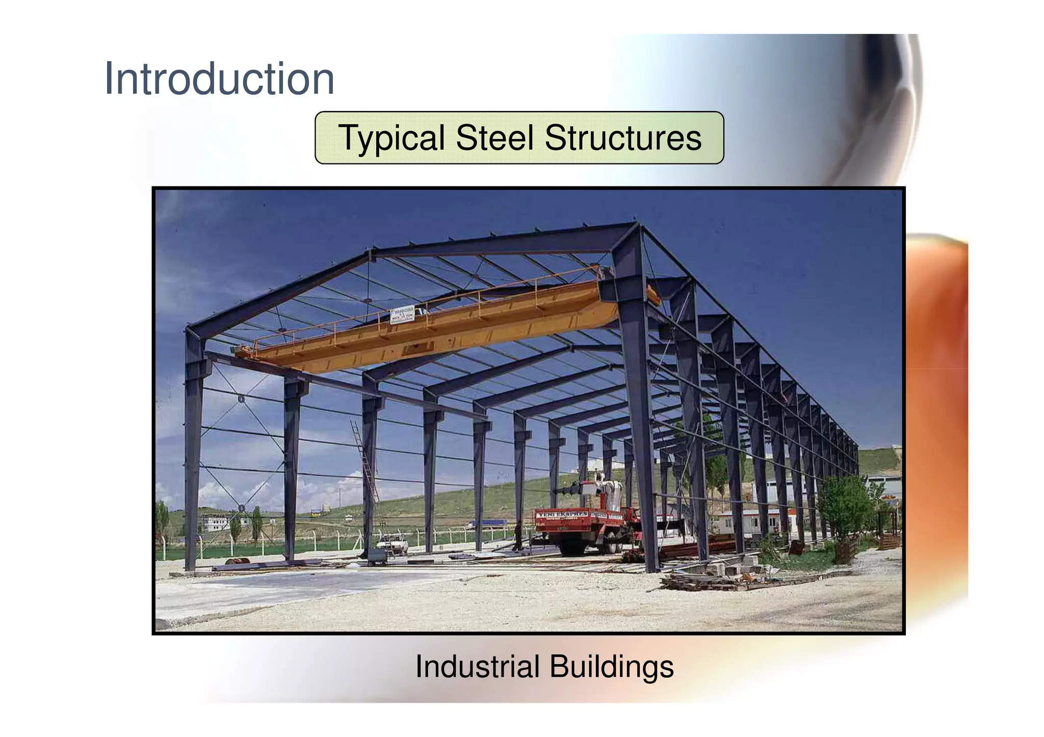
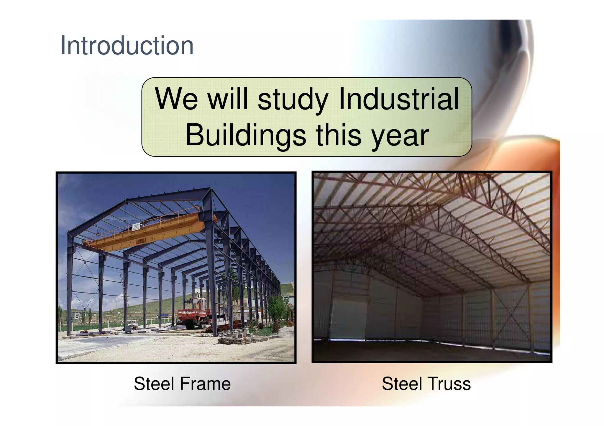
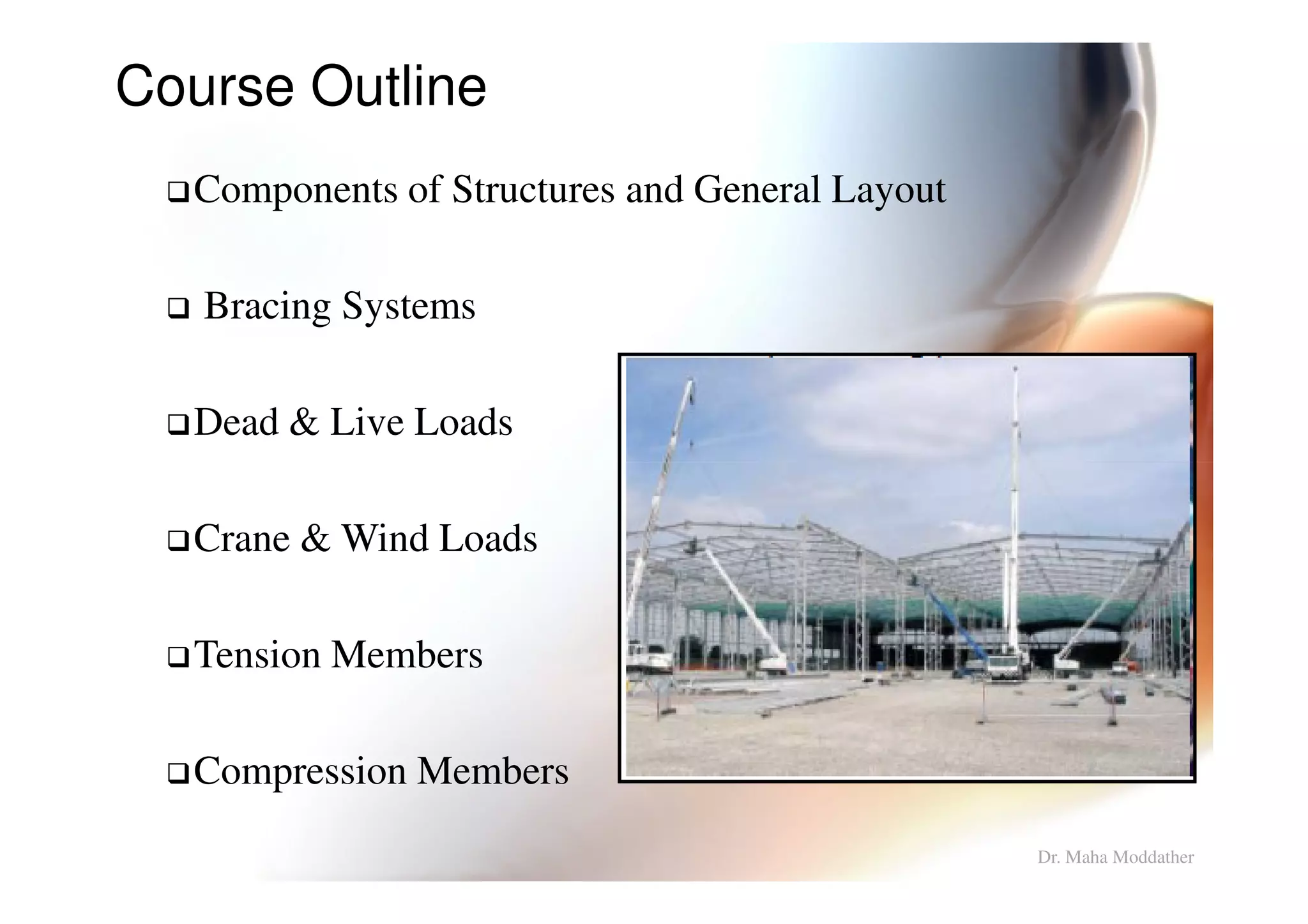
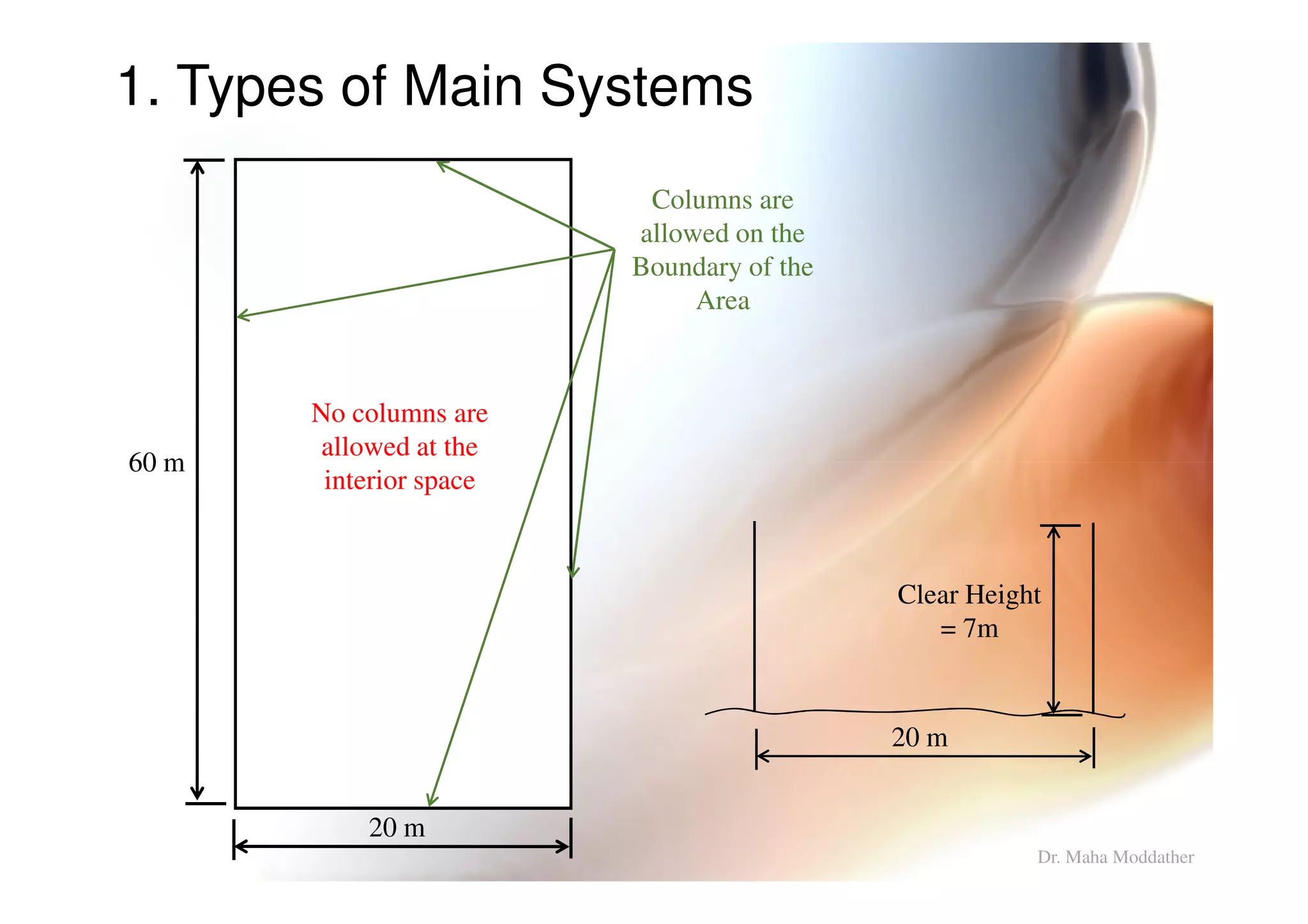
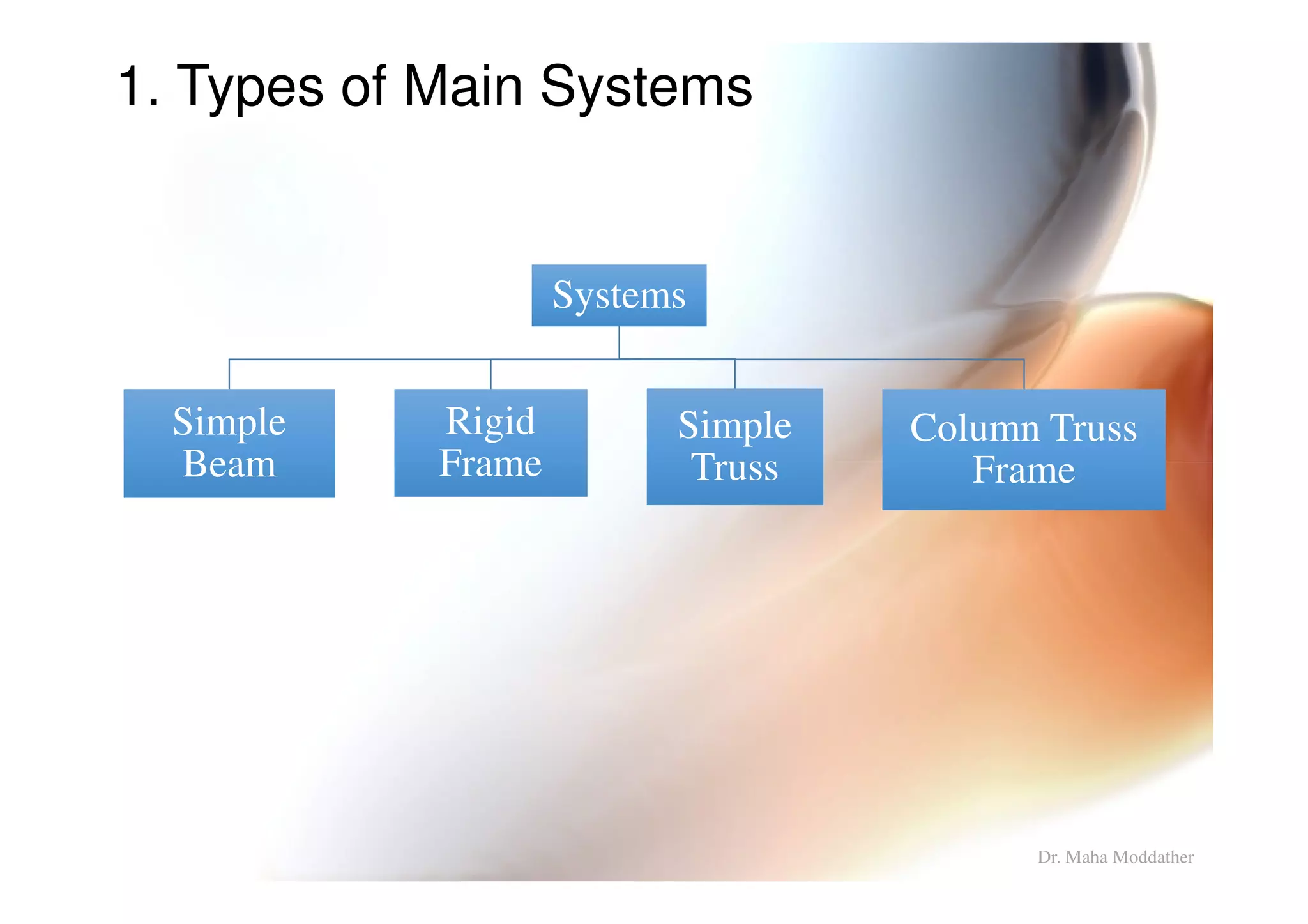
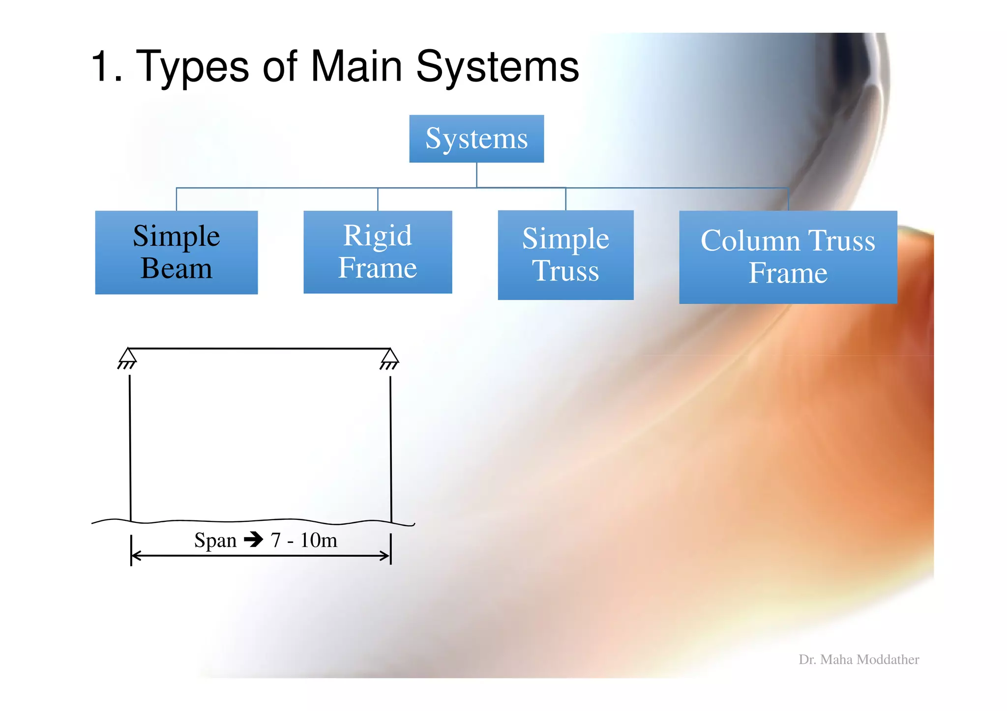


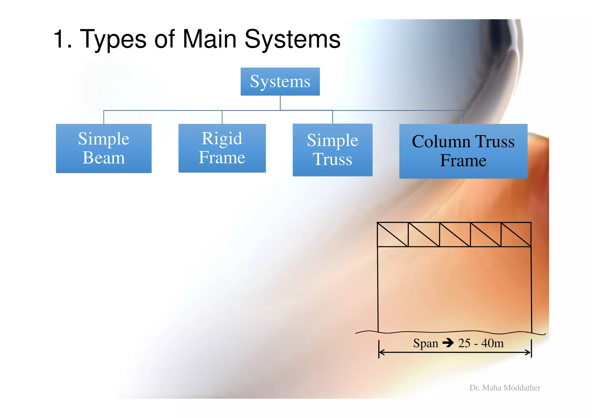
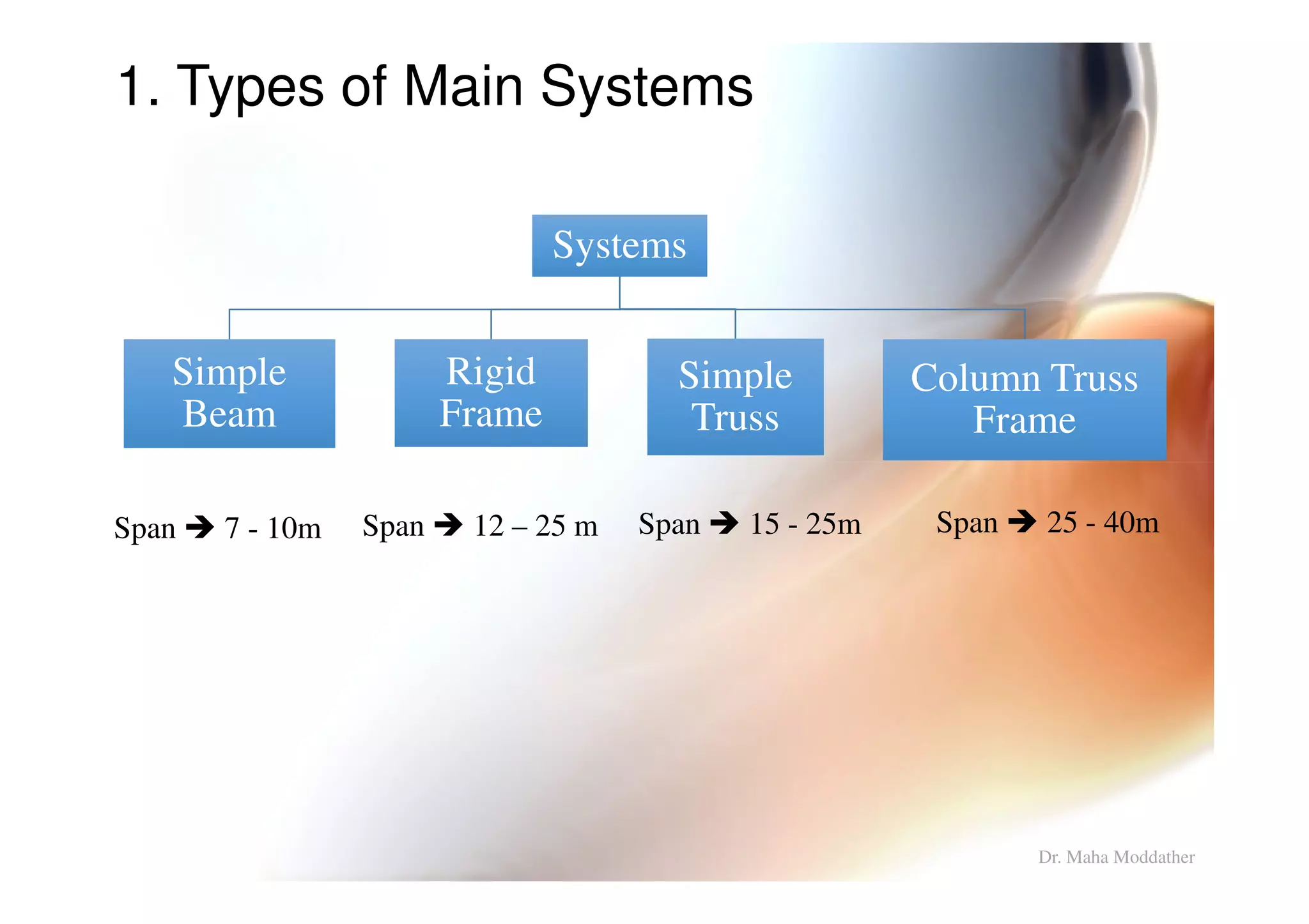
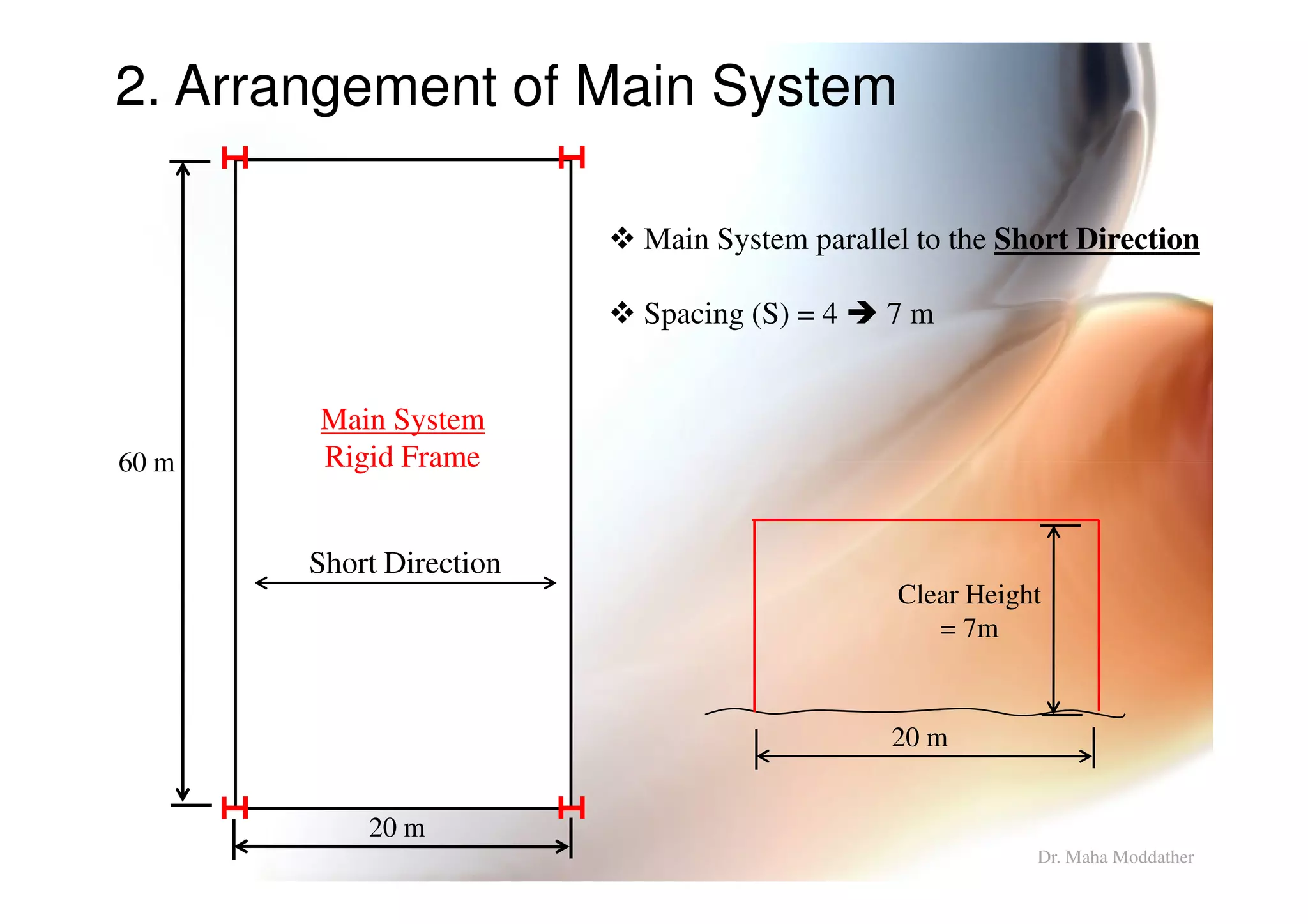
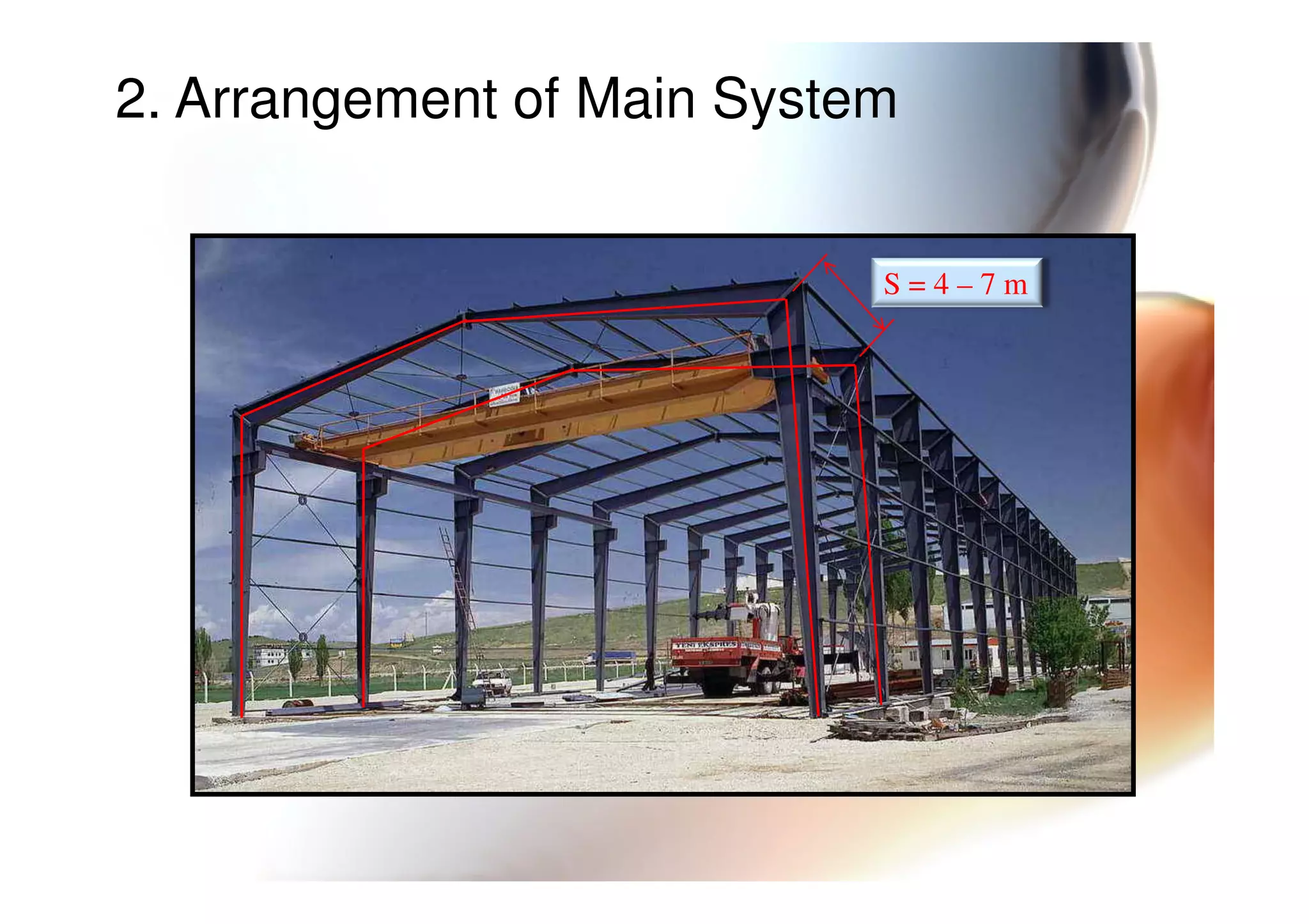
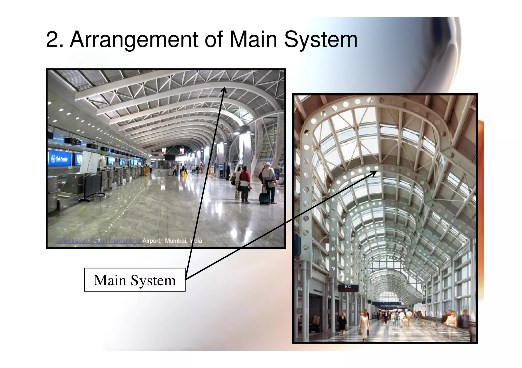
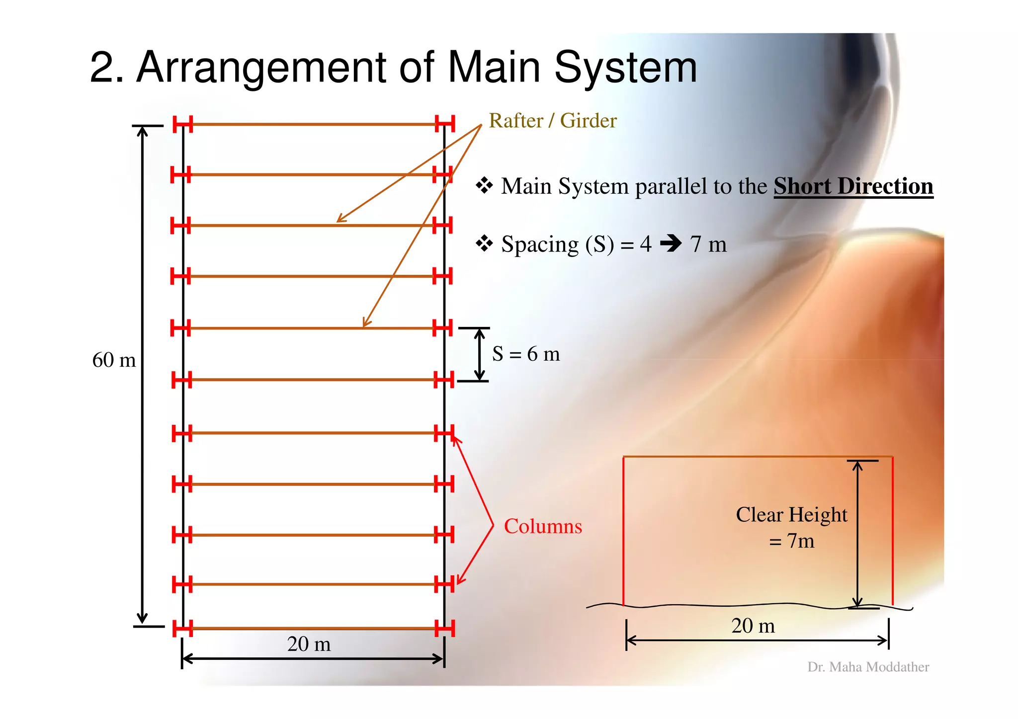
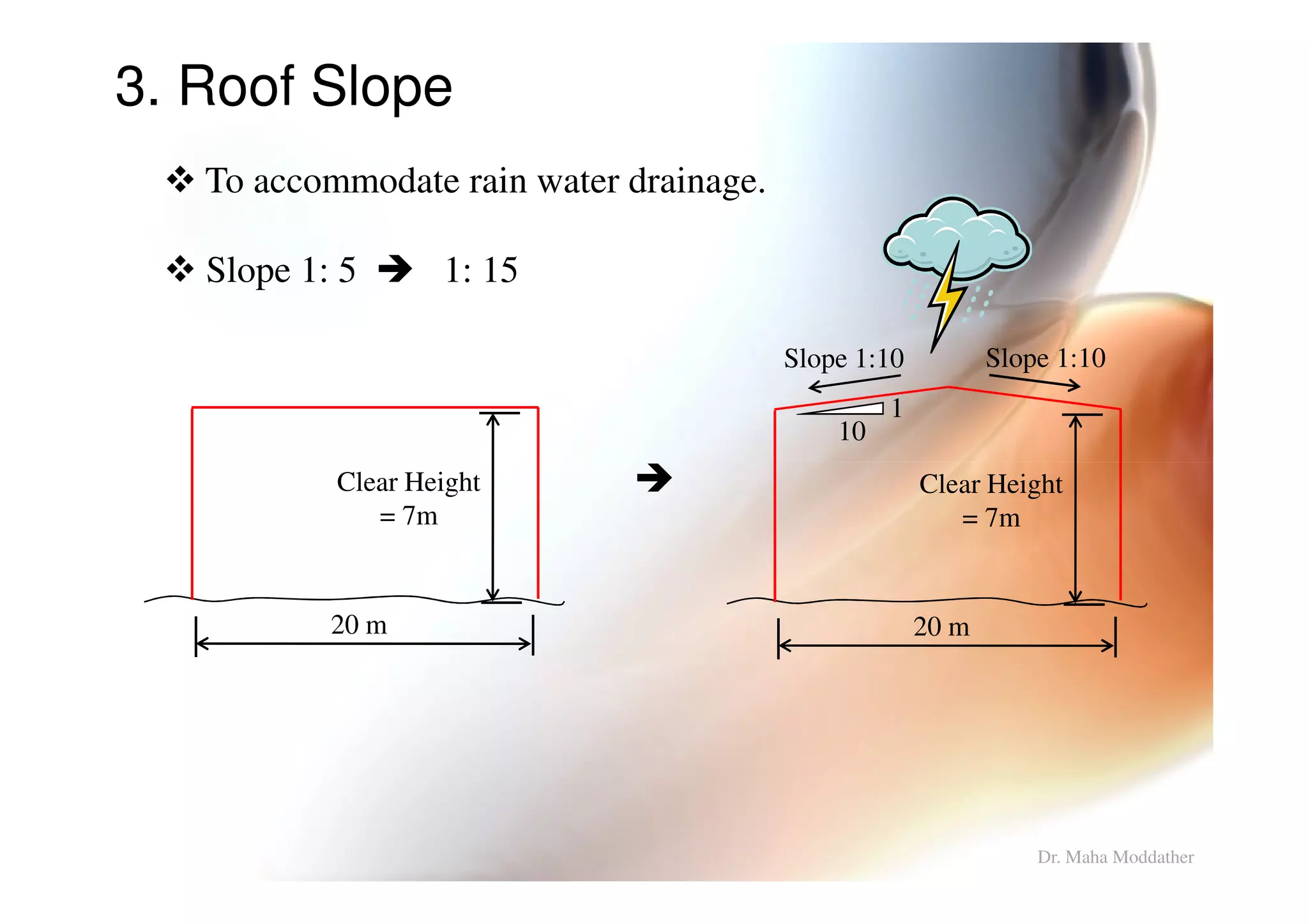
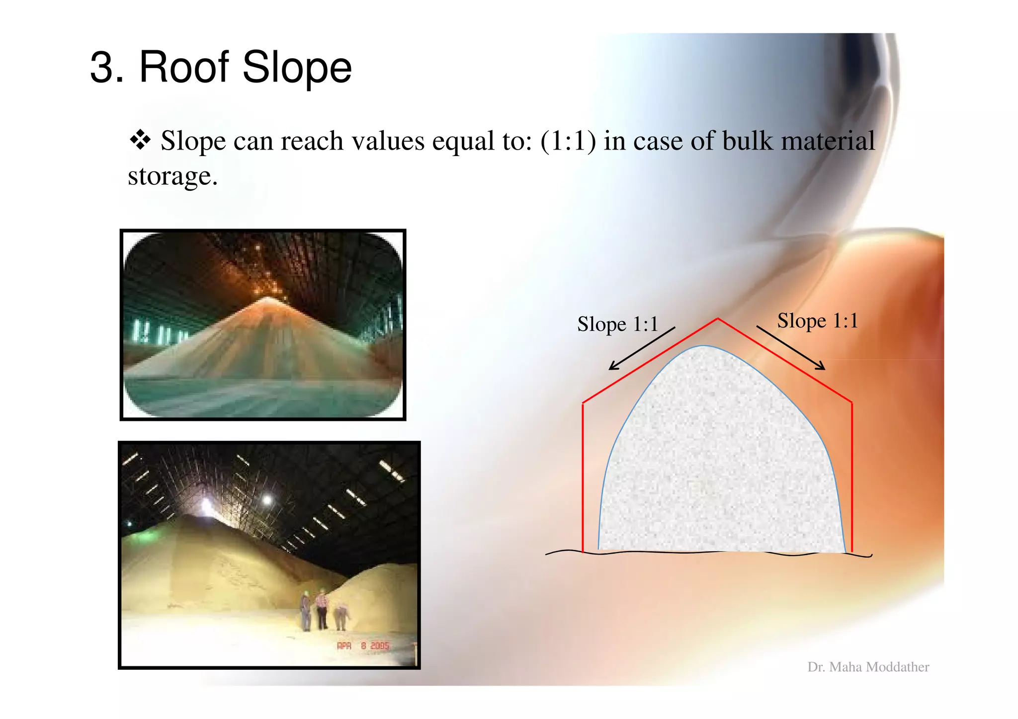
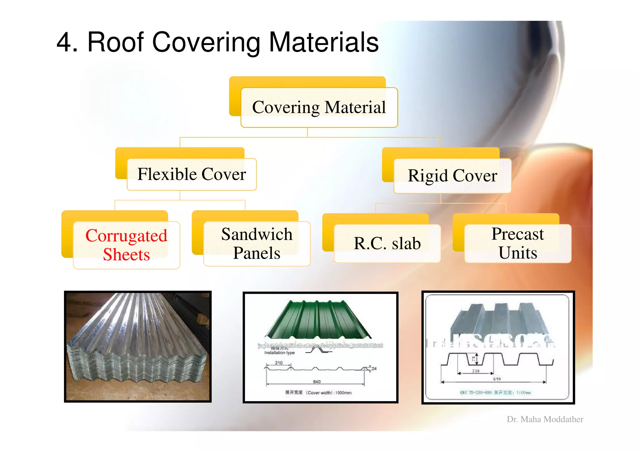
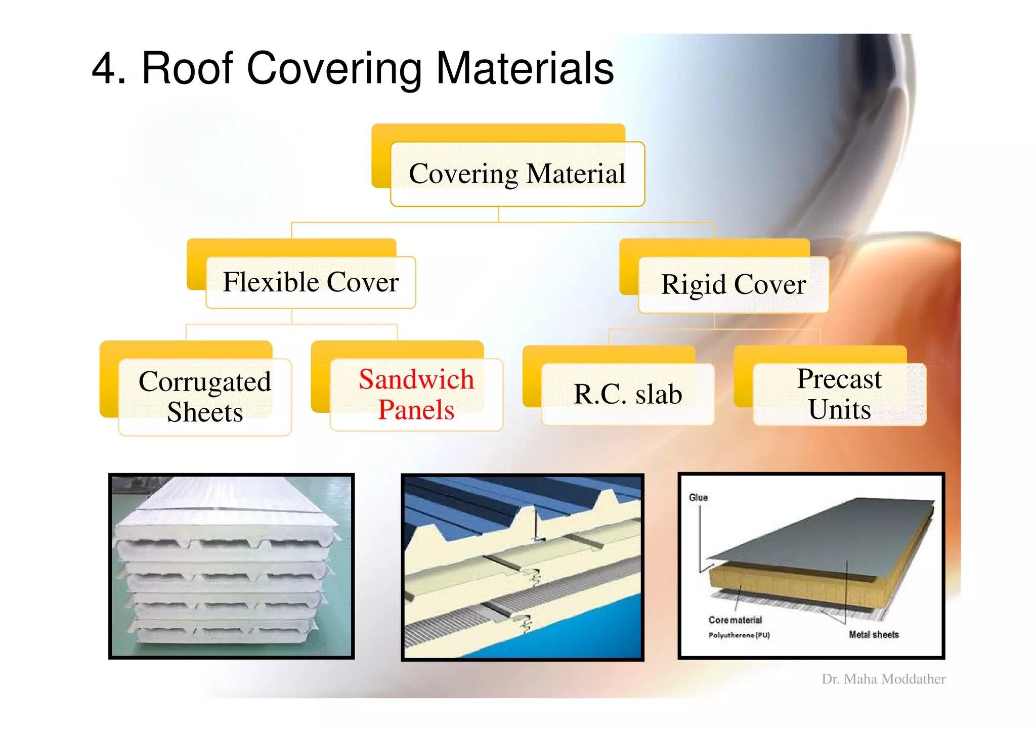
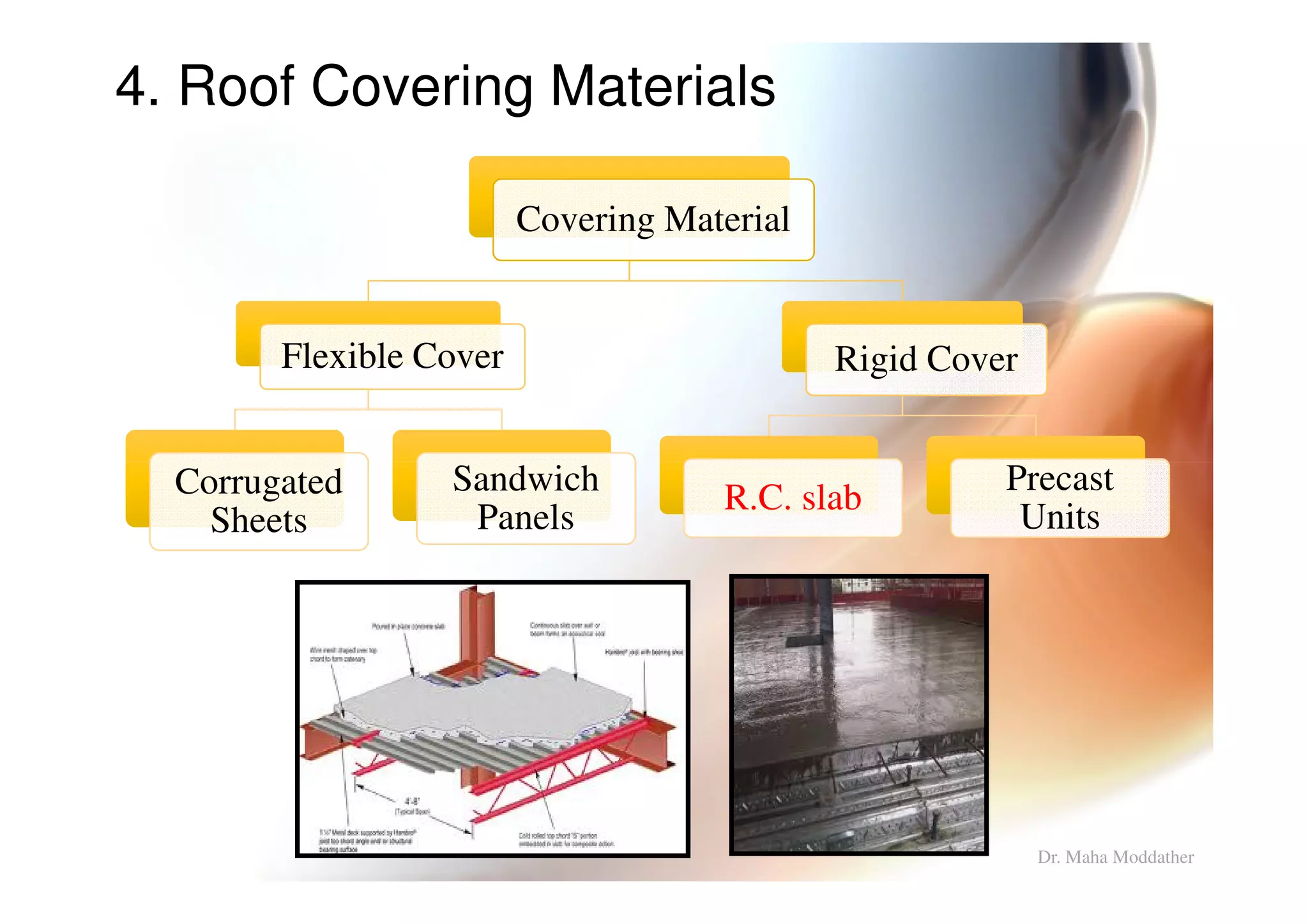
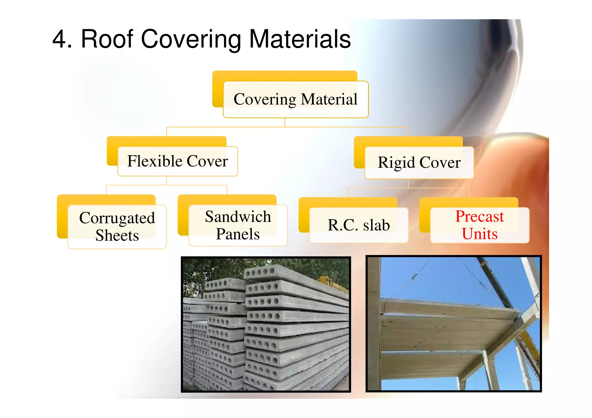
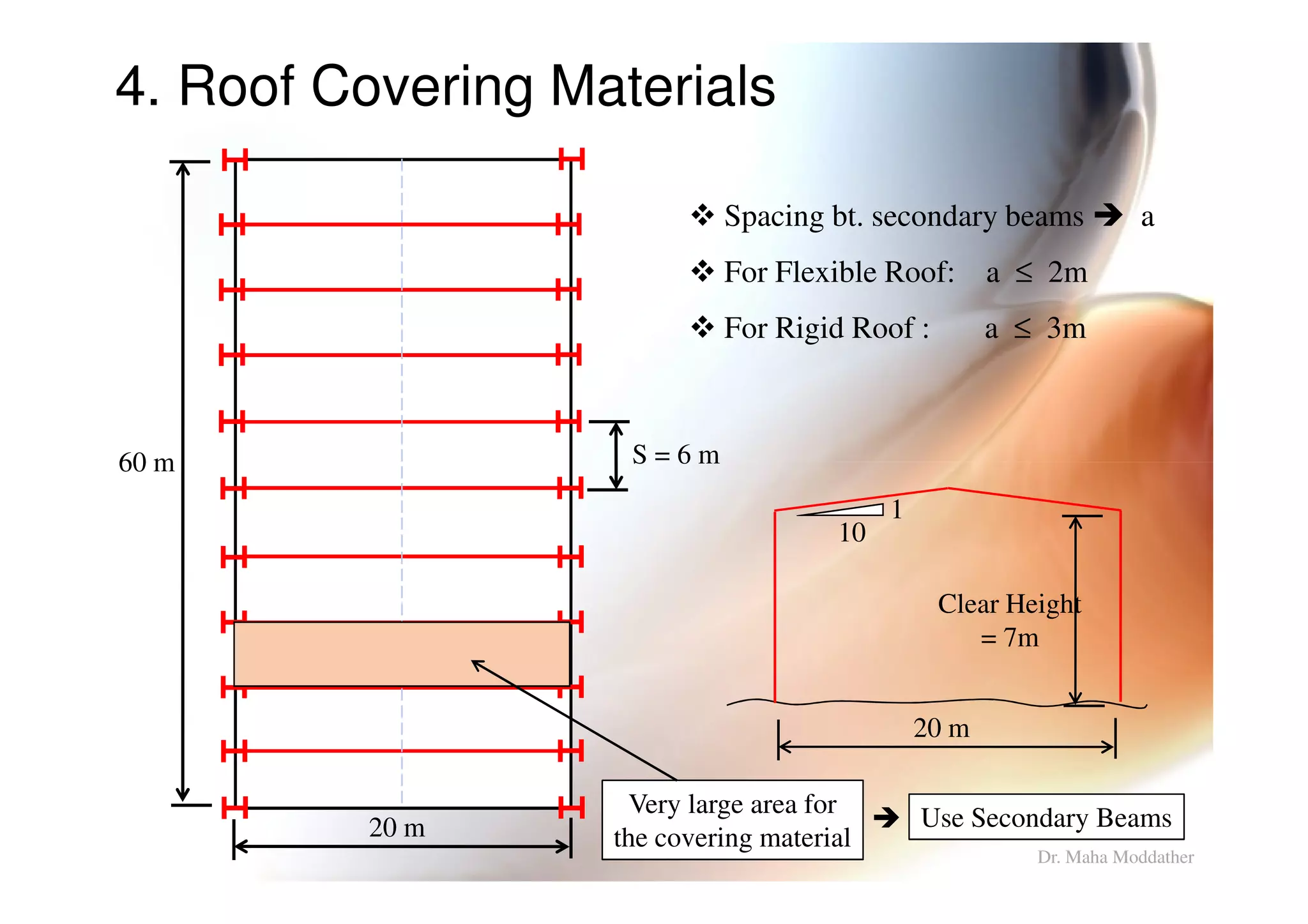
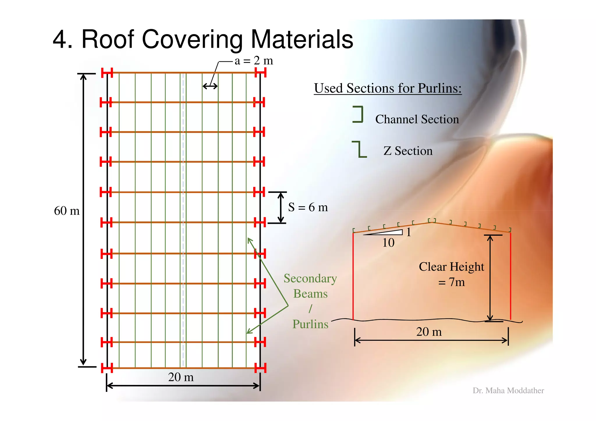
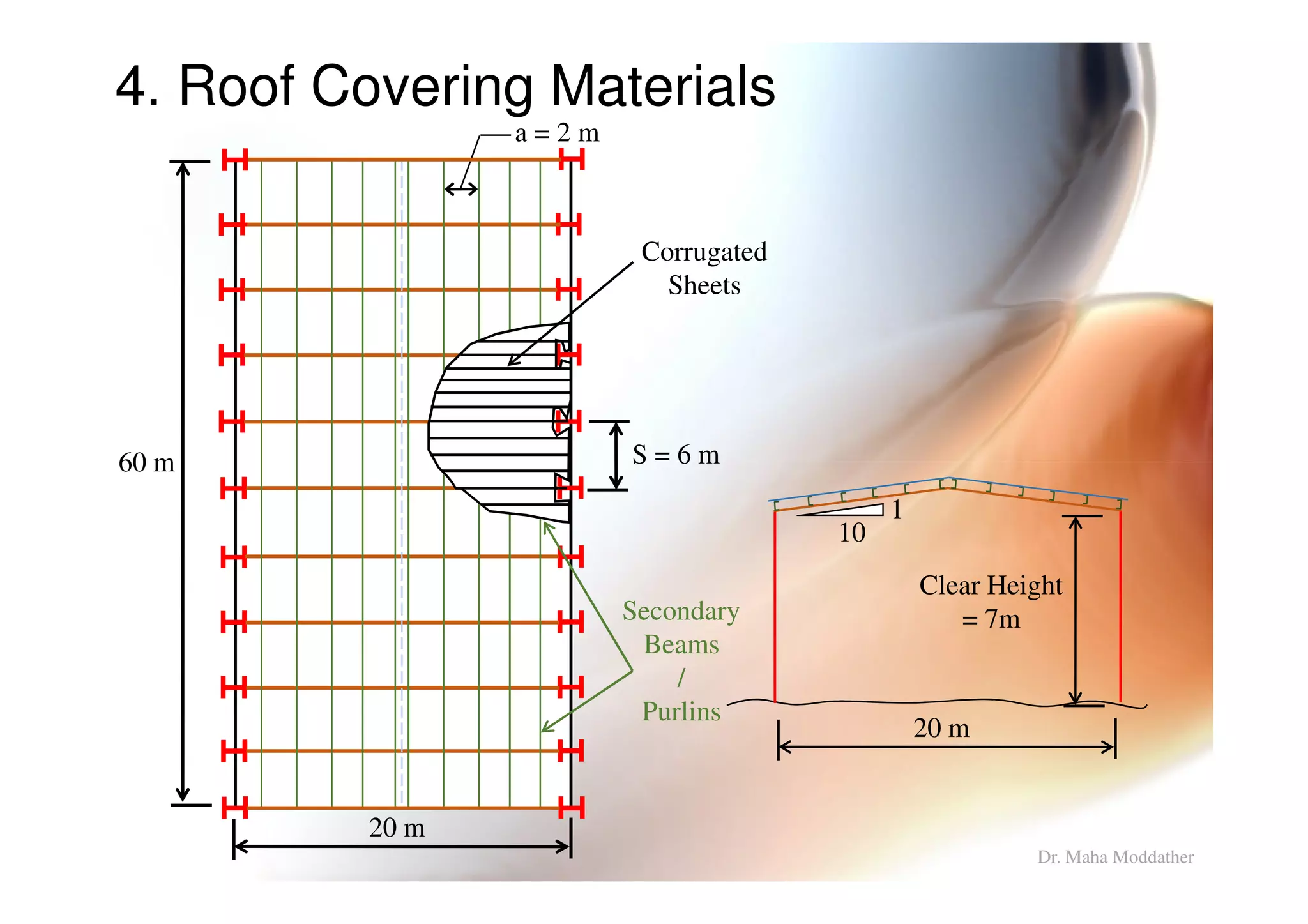
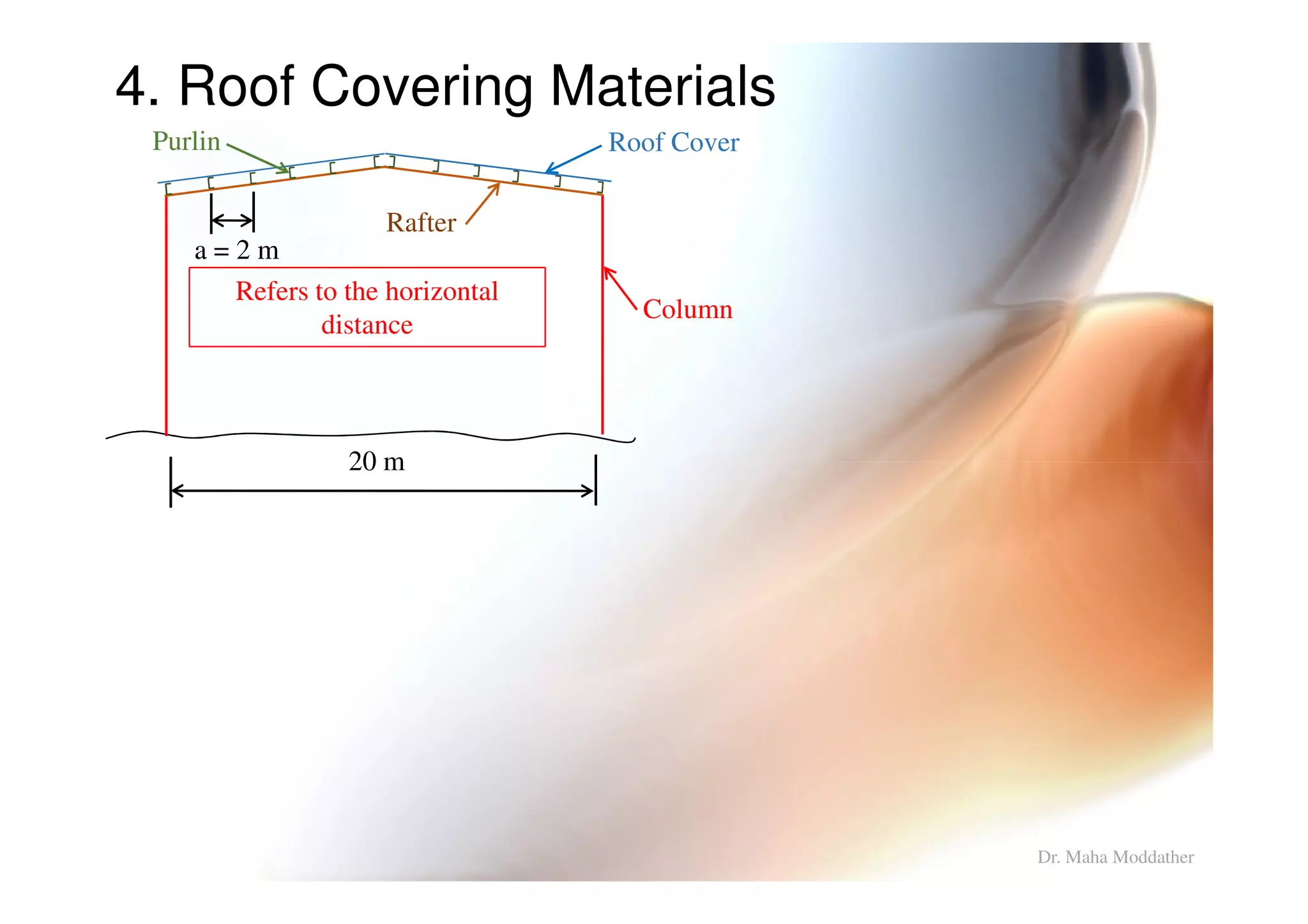
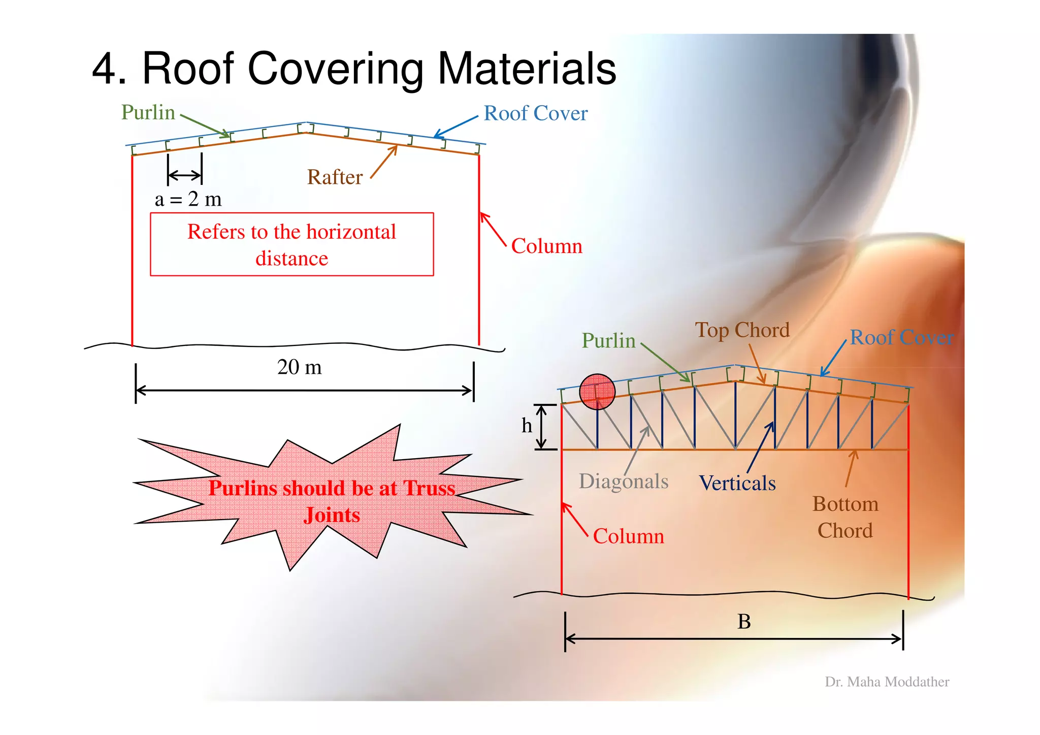

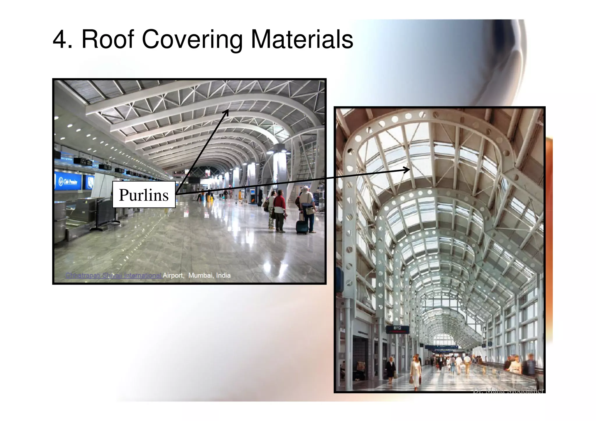
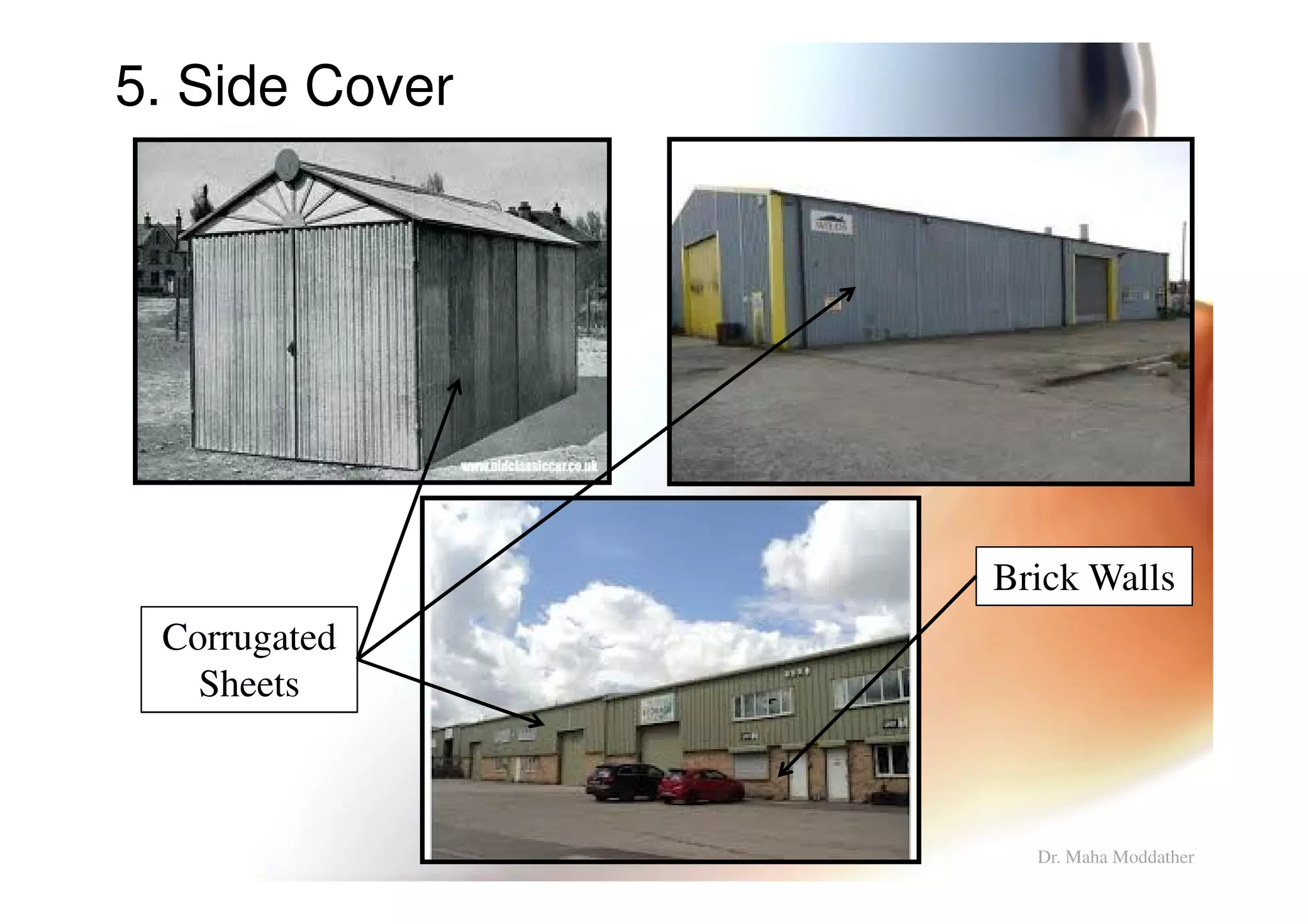
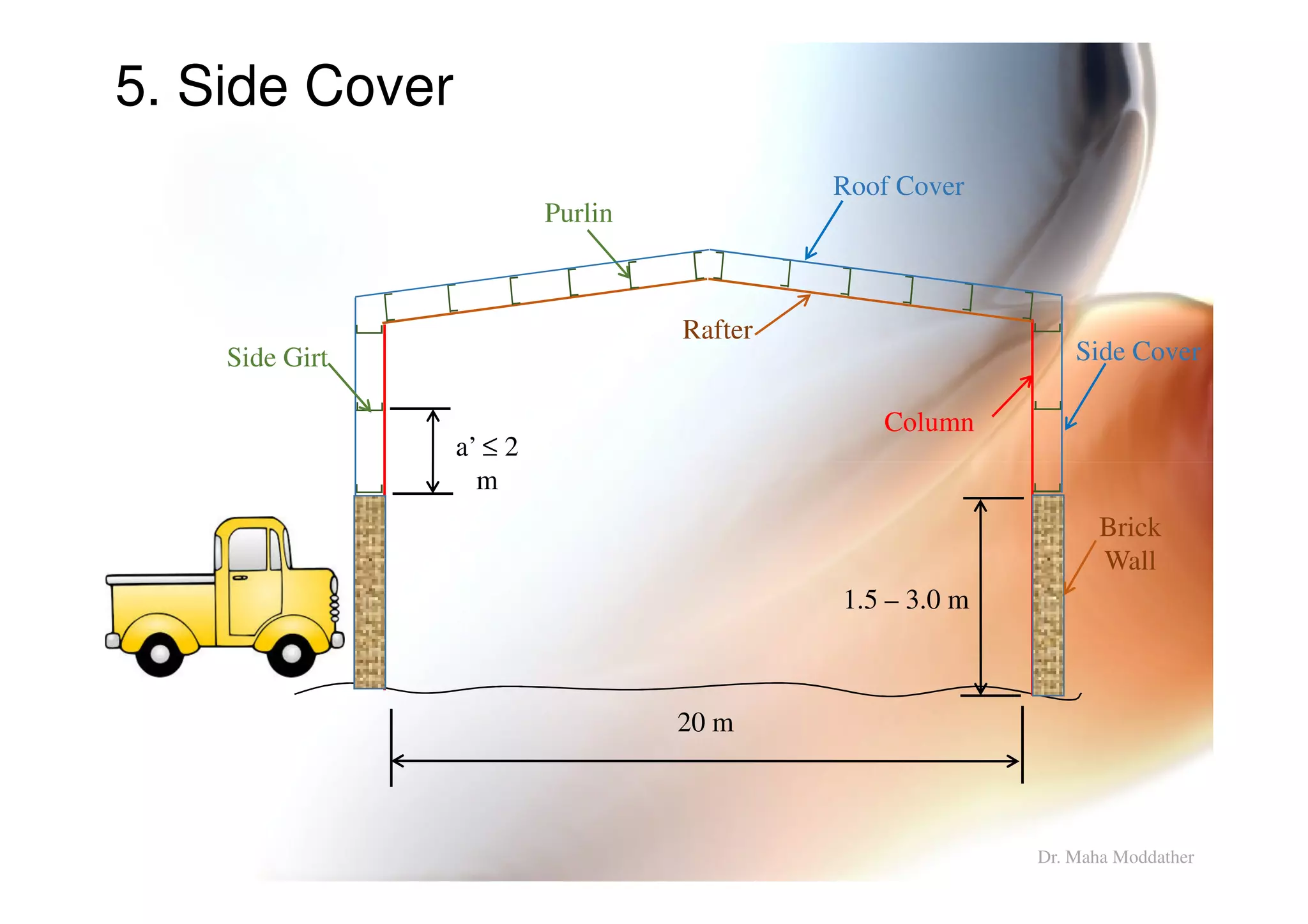
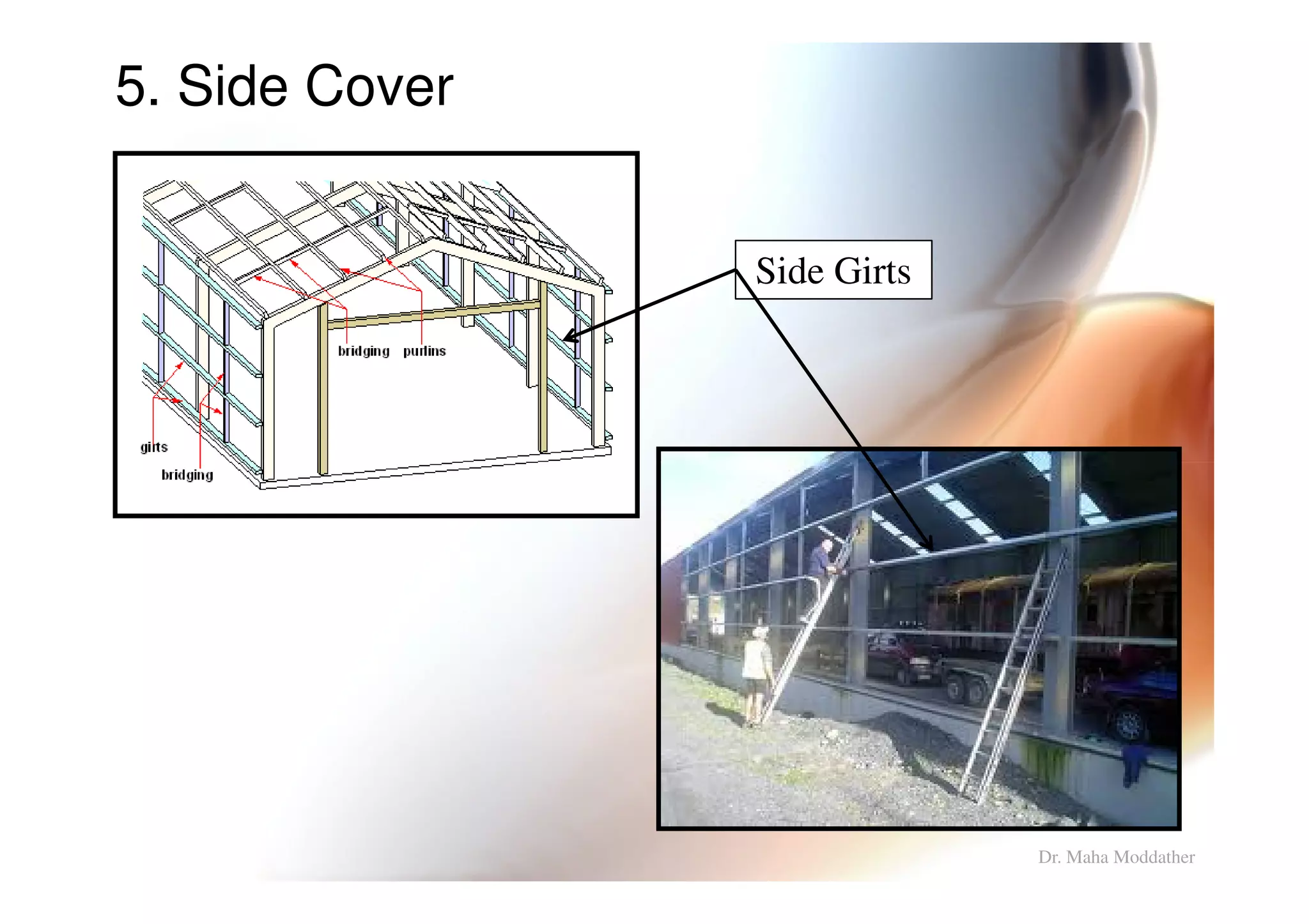
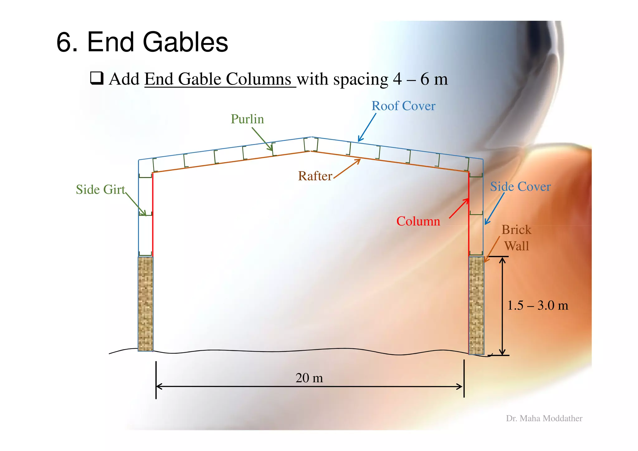
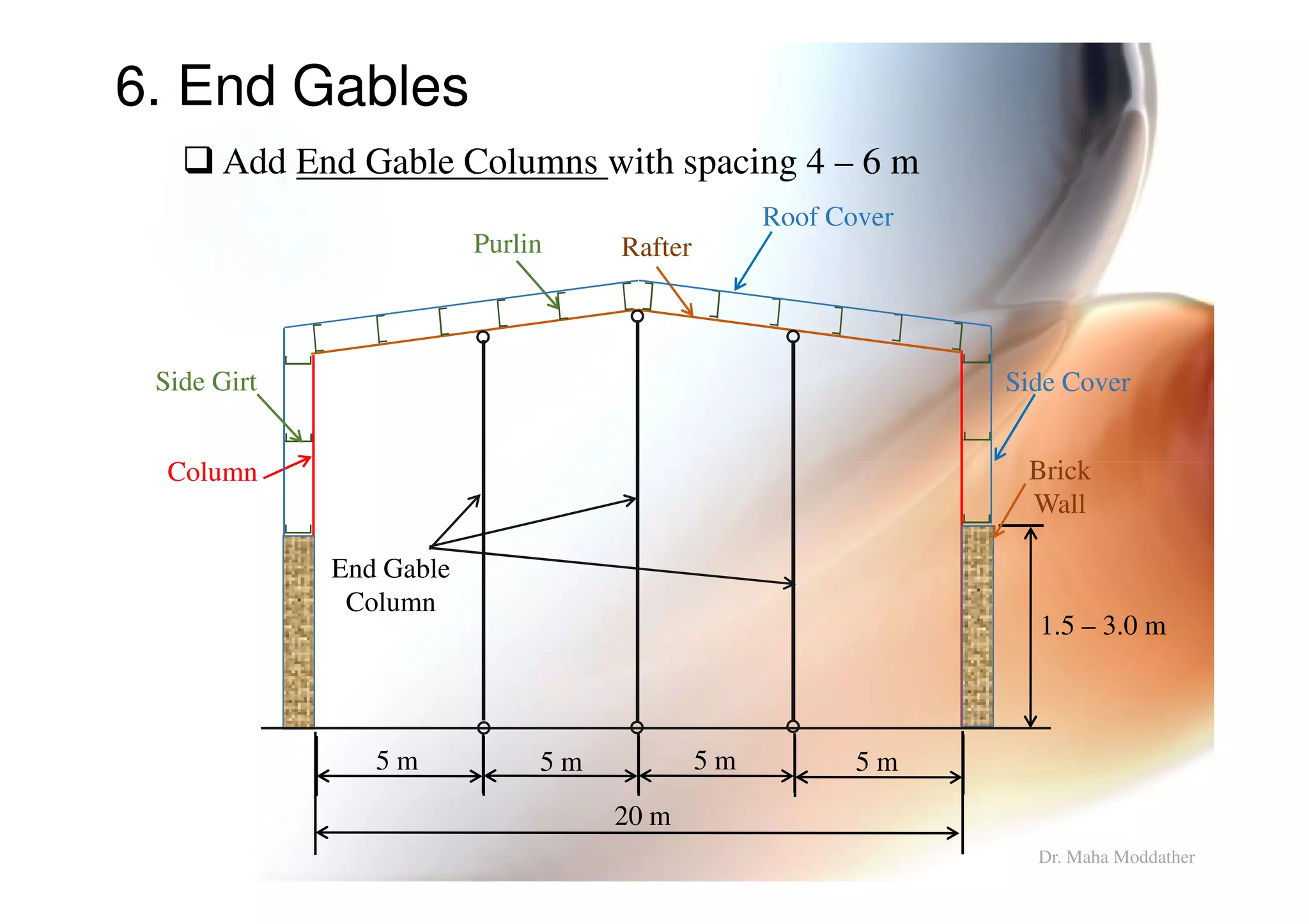
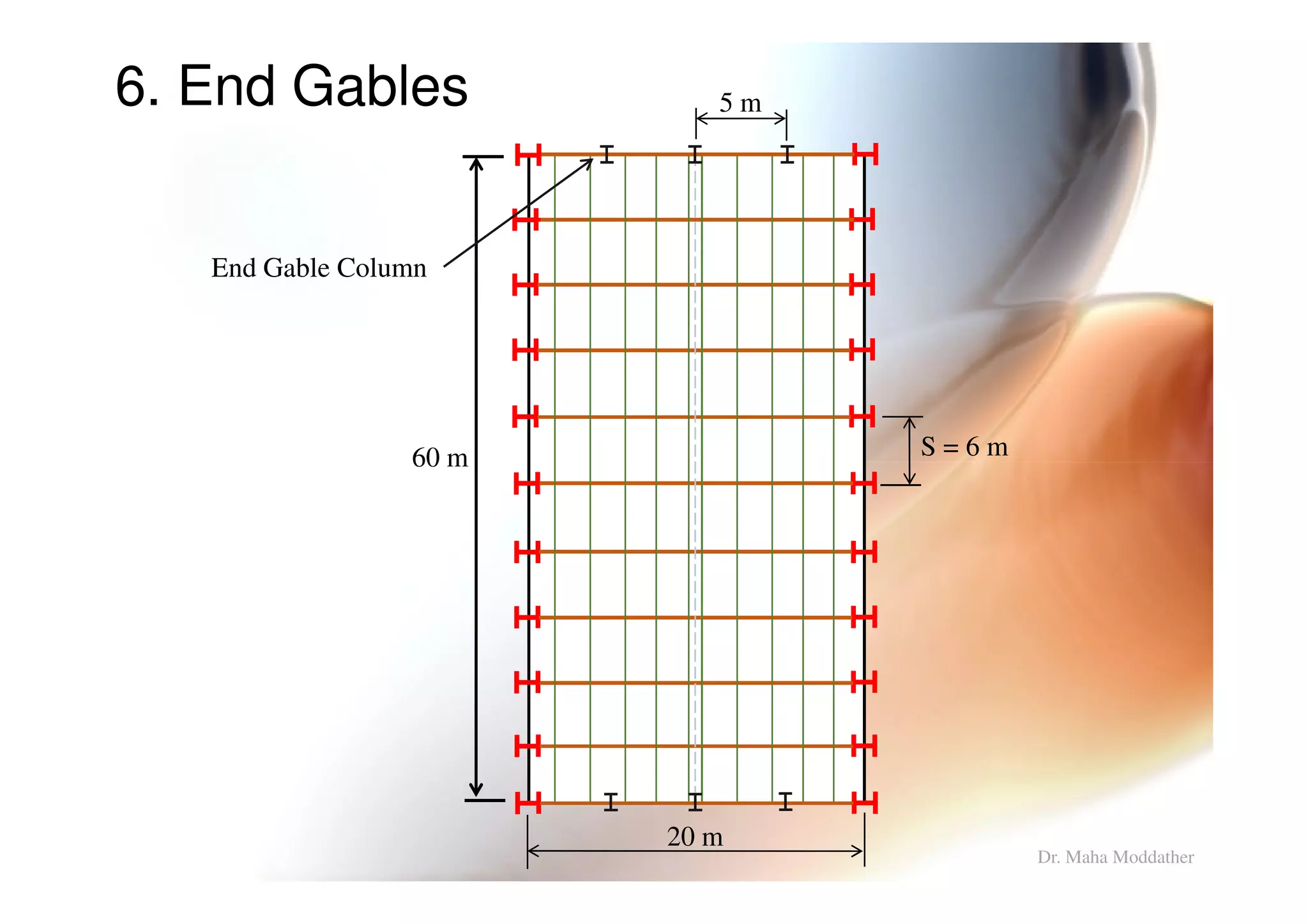
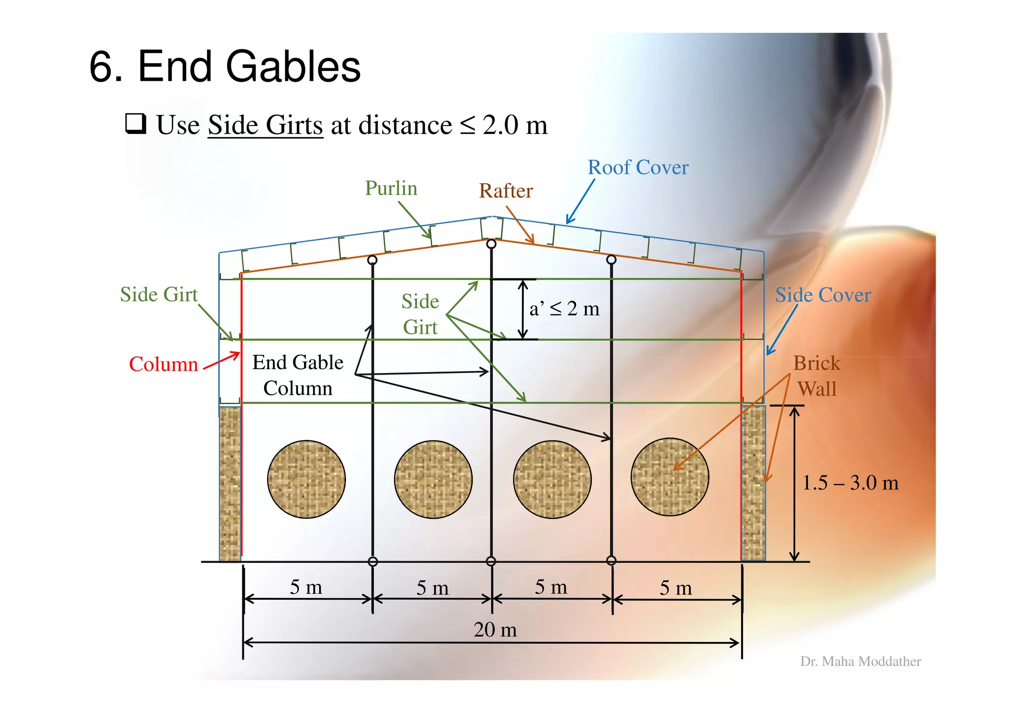
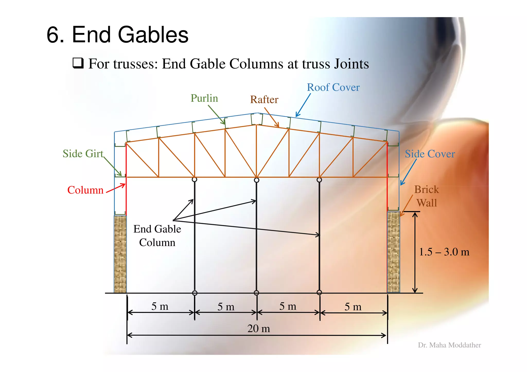
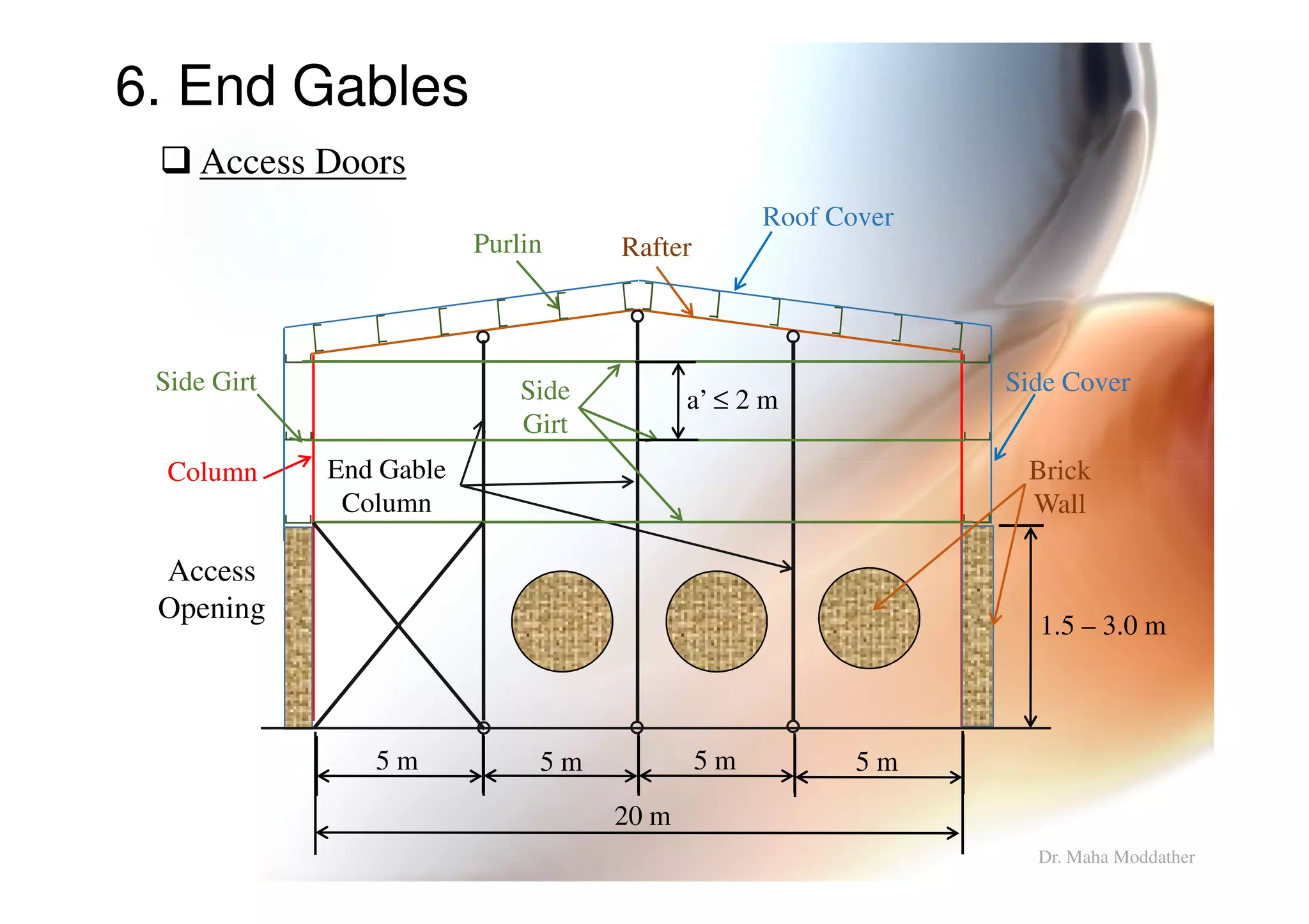
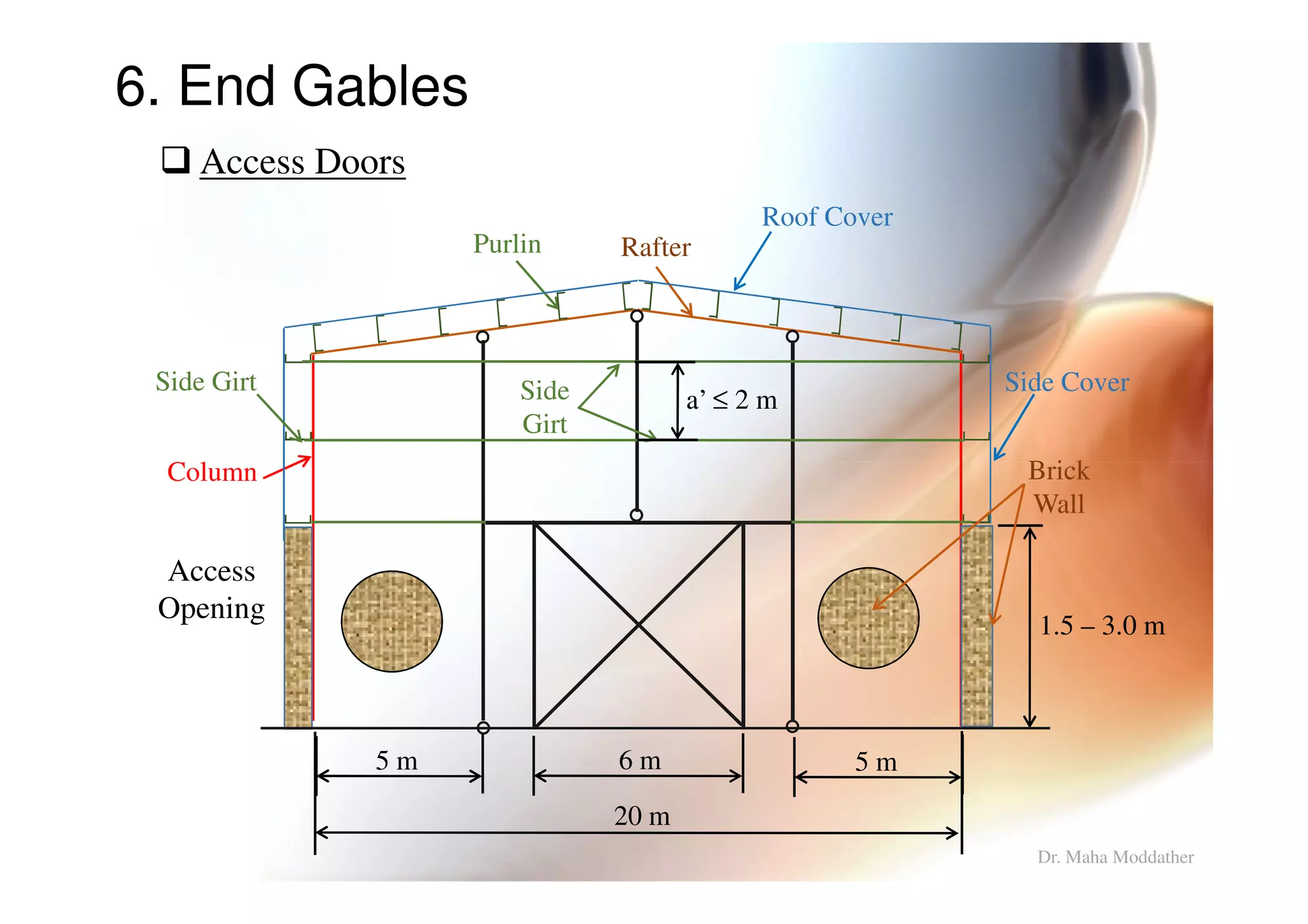
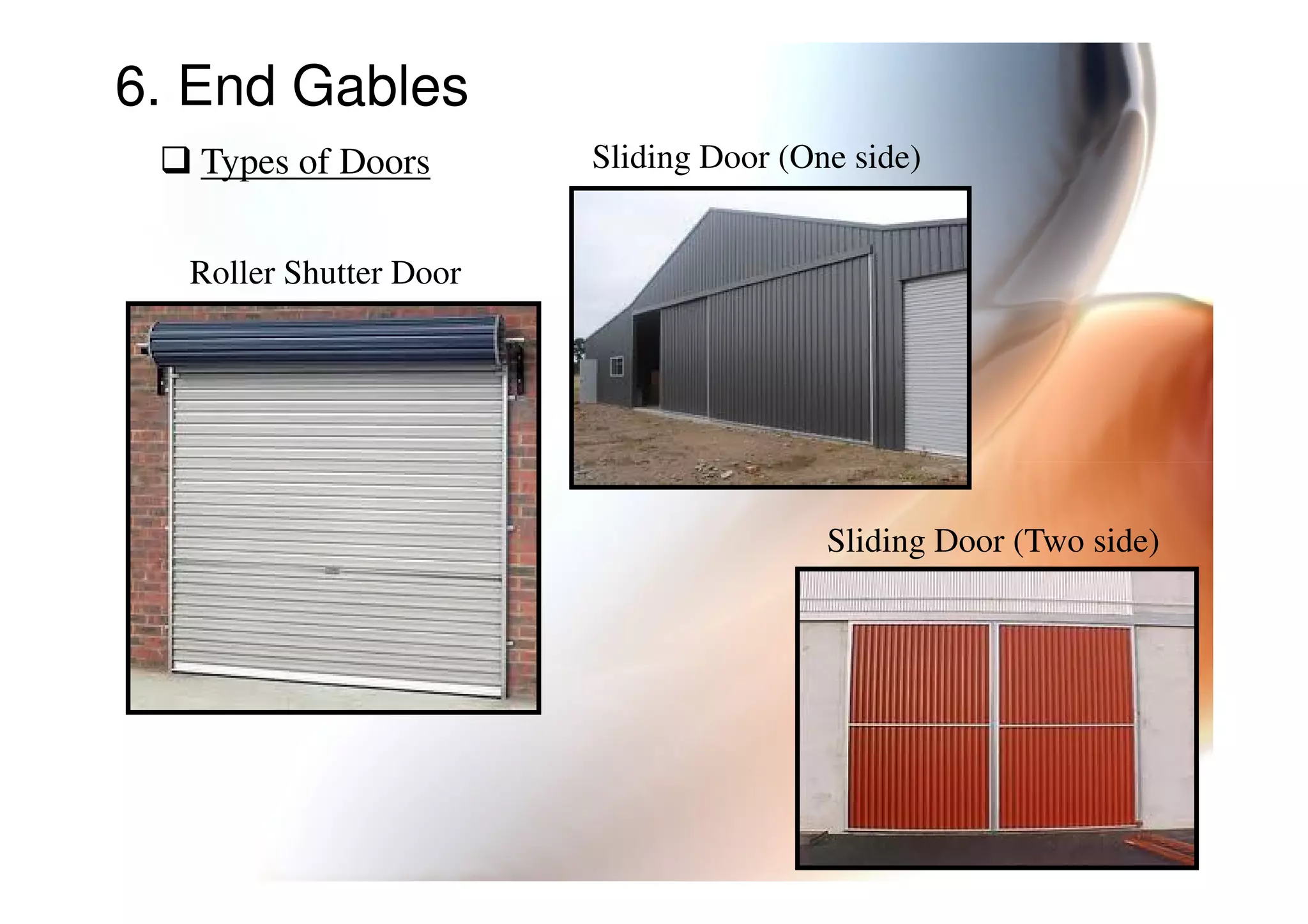
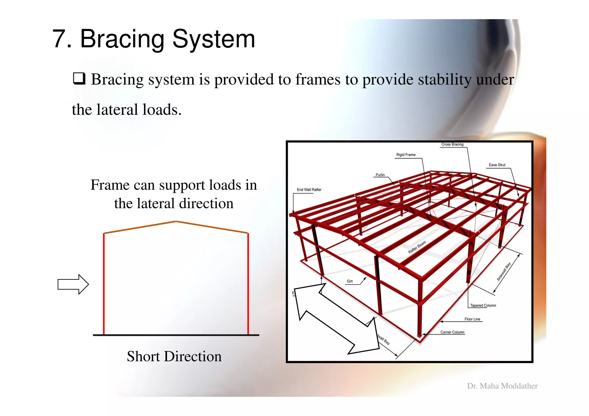
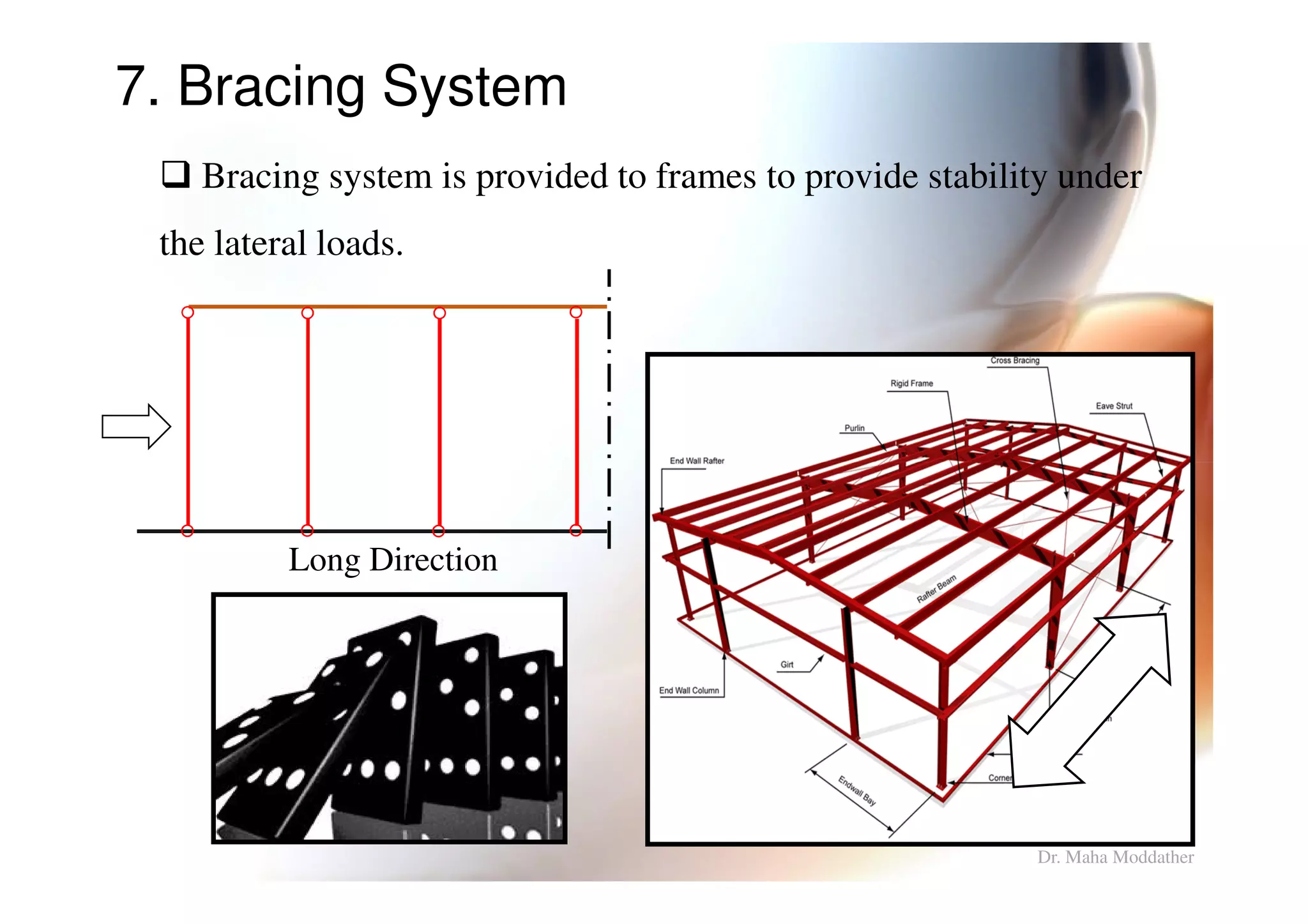
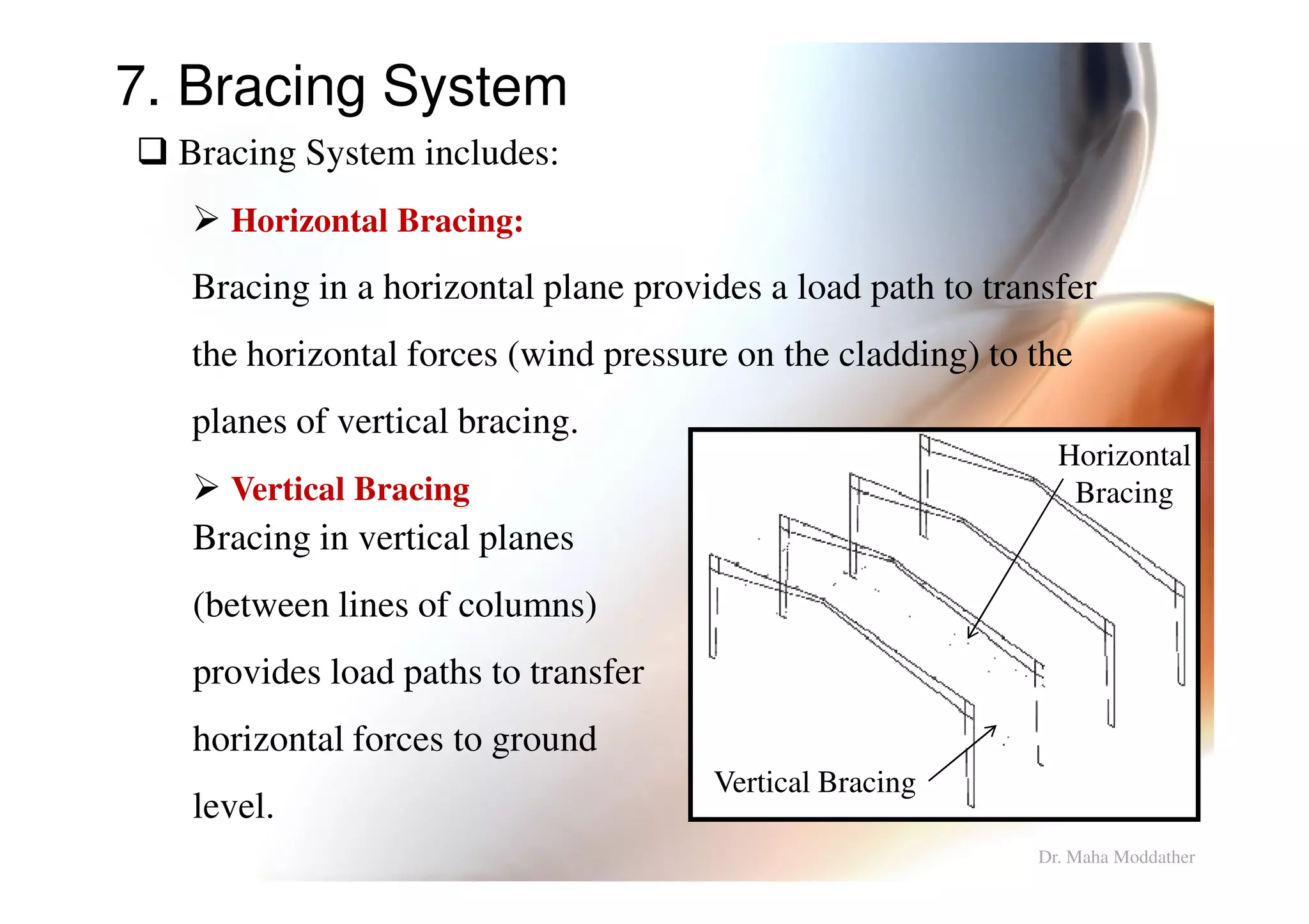
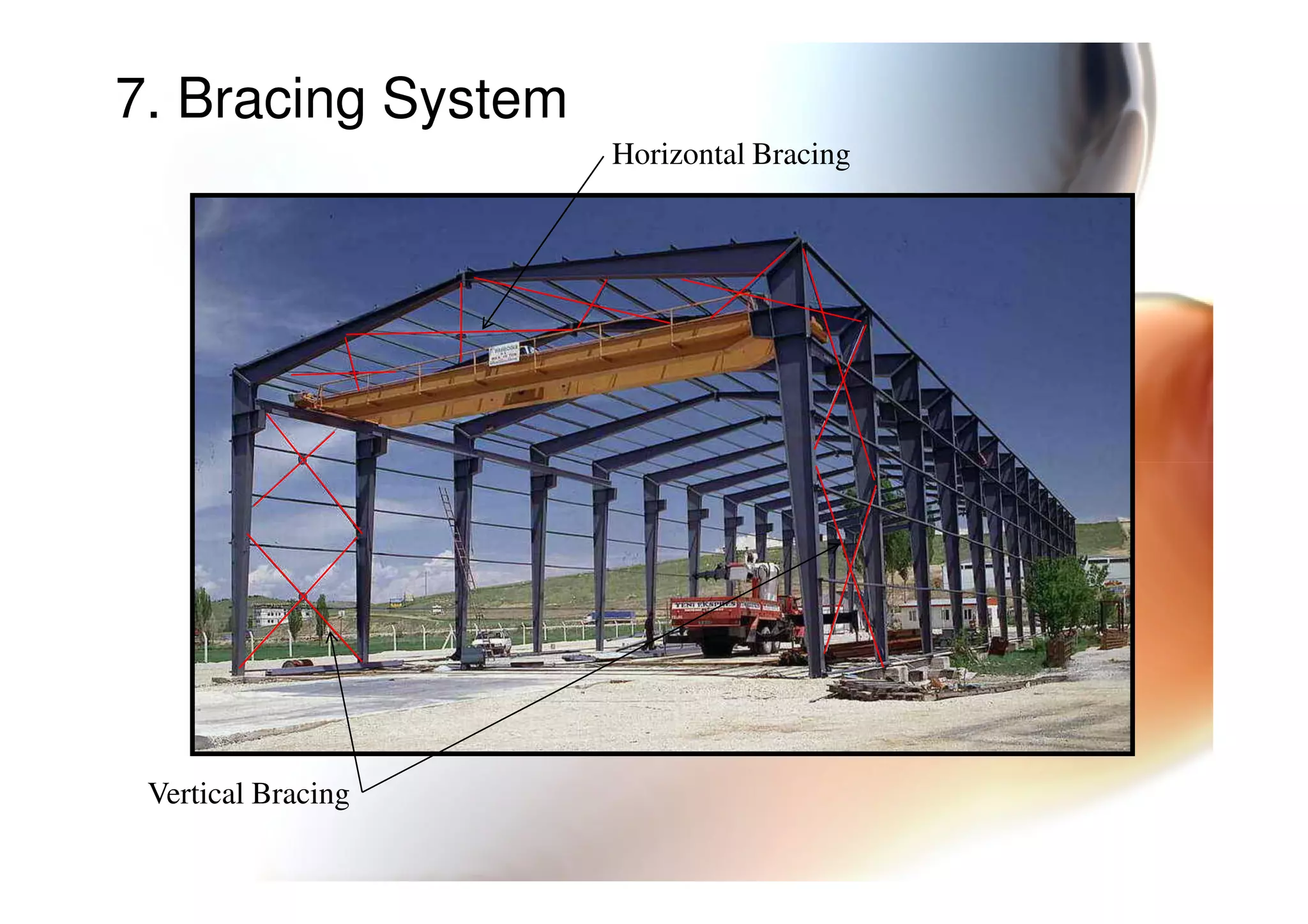
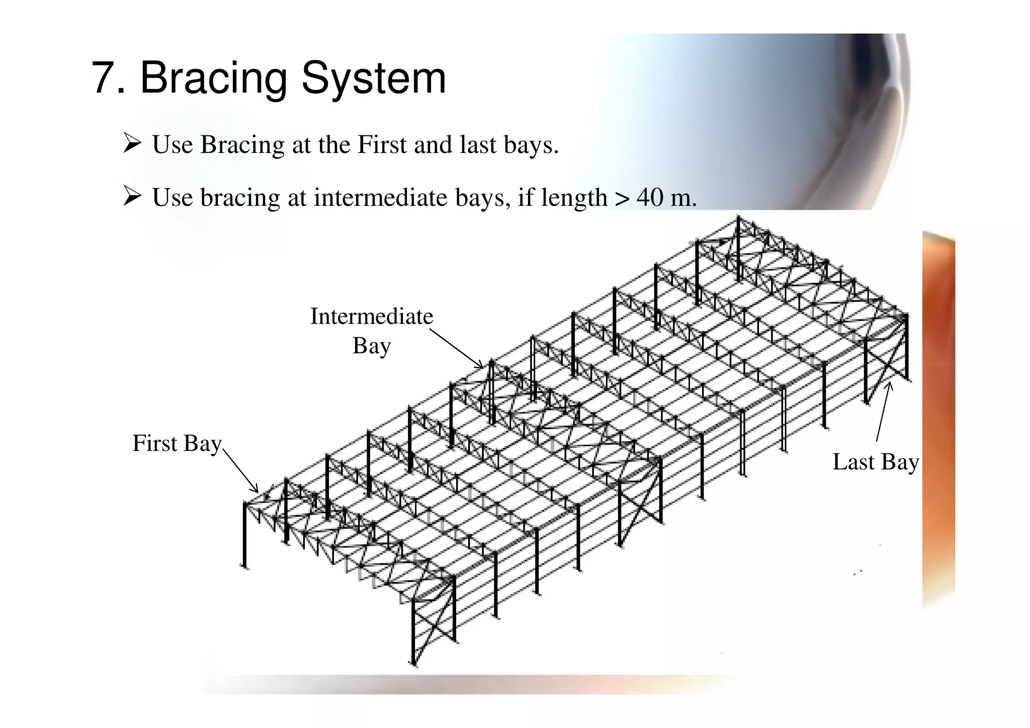

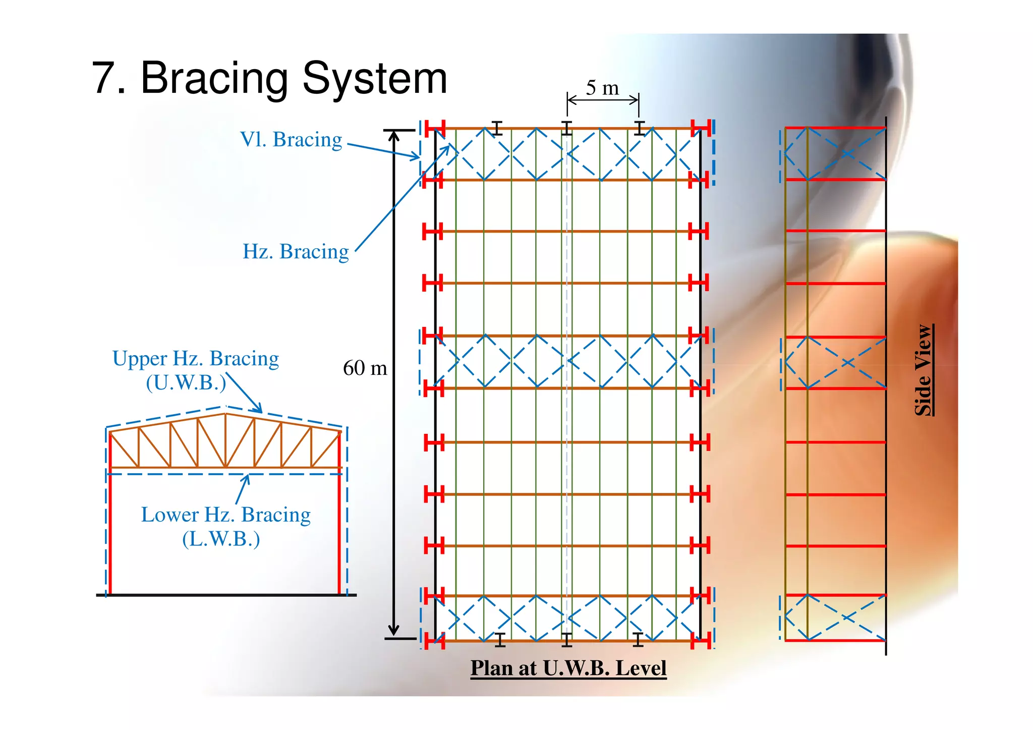

This document provides information on general layout and design of steel industrial buildings, including: 1. Main structural systems used for different span lengths. 2. Arrangement of structural members including columns, rafters, purlins, side girts and bracing. 3. Design considerations for roof slope, covering materials, side walls and end gables. 4. Types of bracing systems used to provide stability under lateral loads.


