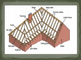
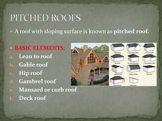
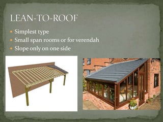
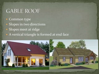
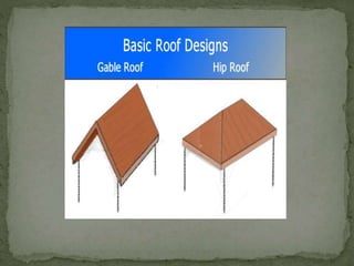
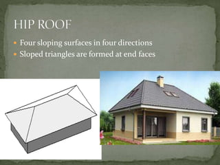
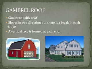
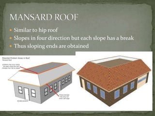
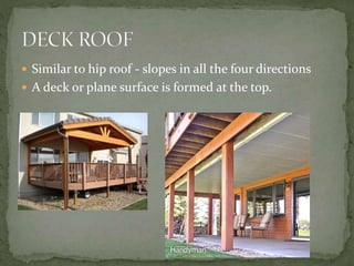
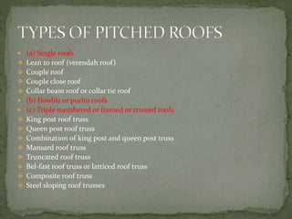
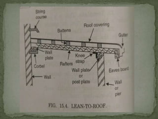
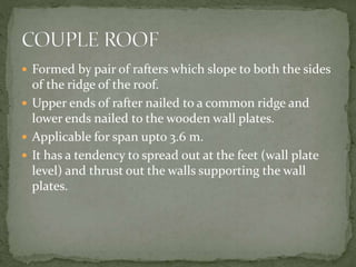
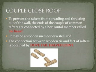
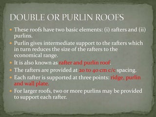
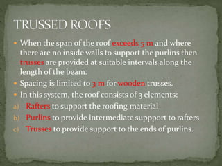
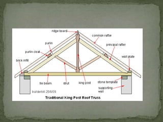
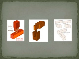
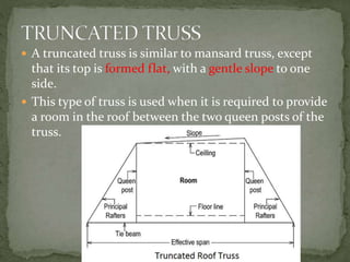
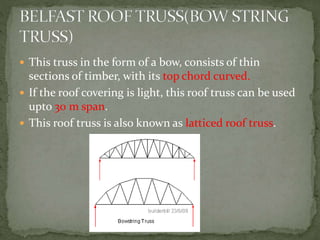
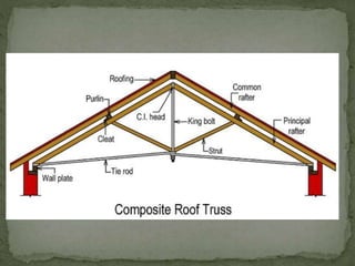
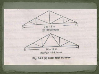
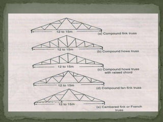
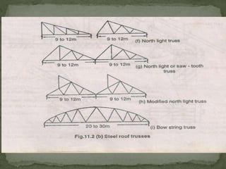
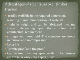
ANAND.T
ASSISTANT PROFESSOR
CIVIL ENGG-KCT
BUILDING CONSTRUCTION
 A roof with sloping surface is known as pitched roof.
 BASIC ELEMENTS:
a. Lean to roof
b. Gable roof
c. Hip roof
d. Gambrel roof
e. Mansard or curb roof
f. Deck roof
 Simplest type
 Small span rooms or for verendah
 Slope only on one side
 Common type
 Slopes in two directions
 Slopes meet at ridge
 A vertical triangle is formed at end face
 Four sloping surfaces in four directions
 Sloped triangles are formed at end faces
 Similar to gable roof
 Slopes in two direction but there is a break in each
slope
 A vertical face is formed at each end.
 Similar to hip roof
 Slopes in four direction but each slope has a break
 Thus sloping ends are obtained
 Similar to hip roof - slopes in all the four directions
 A deck or plane surface is formed at the top.
 (a) Single roofs
 Lean to roof (verendah roof)
 Couple roof
 Couple close roof
 Collar beam roof or collar tie roof
 (b) Double or purlin roofs
 (c) Triple membered or framed or trussed roofs
 King post roof truss
 Queen post roof truss
 Combination of king post and queen post truss
 Mansard roof truss
 Truncated roof truss
 Bel-fast roof truss or latticed roof truss
 Composite roof truss
 Steel sloping roof trusses
 Consists of only common rafters secured at the ridge
and wall plate.
 Small span where no intermediate support is required
for the rafters
 Here purlins are introduced to support common
rafters at intermediate point
 Used when span exceeds 5m.
 FUNCTION OF PURLIN
 To tie the rafters together
 To act as an intermediate support to the rafters
 3 sets of memebers: (i) common rafters, (ii) purlins
and (iii) trusses.
 Purlin gives intermediate support to the rafters.
 A trussed roof is provided when
The span of the room is greater than 5 metres
When the length of the room is large i.e., (where there
are no internal walls or partitions to support the
purlins)
 Simplest type and suitable upto max span of 2.5 m.
 Rafters slope on one side only (usual slope 30 degree)
 Also known as pent roof or aisle roof
 Wall on one side is higher than the other side
 Wooden wall plates supported by corbel provided at 1m
centre to centre.
 Common rafters are nailed to wooden wall plate at their
upper end and nailed to wooden post plate at their lower
end.
 Iron knee straps and bolts are also used to connect the
rafters.
 Applicable for sheds, out-houses attached to main
building.
 Formed by pair of rafters which slope to both the sides
of the ridge of the roof.
 Upper ends of rafter nailed to a common ridge and
lower ends nailed to the wooden wall plates.
 Applicable for span upto 3.6 m.
 It has a tendency to spread out at the feet (wall plate
level) and thrust out the walls supporting the wall
plates.
 To prevent the rafters from spreading and thrusting
out of the wall, the ends of the couple of common
rafters are connected by a horizontal member called
‘tie beam’.
 It may be a wooden member or a steel rod.
 The connection between wooden tie and feet of rafters
is obtained by DOVE TAIL HALVED JOINT.
 One tie for each pair of rafters.
 Tie beams also acts as ceiling joists when required.
 Economically suitable for spans upto 4.2 m.
 For increased span or for greater loads, the rafters may
sag in the middle. In order to overcome that, a central
vertical rod called as king rod or king bolt is used to
connect ridge piece and tie beam.
 When the span increases or when the load is more, the
rafters of the couple close roof have the tendency to
bend.
 This is avoided by raising the tie beam and fixing it at
one-third to one-half of the vertical height from wall
plate to the ridge. This raised beam is known as the
collar beam or collar tie.
 Suitable for span upto 5 m.
 Similar to collar roof
 Except that two collar beams crossing each other to
have an appearance of scissors is provided.
 These roofs have two basic elements: (i) rafters and (ii)
purlins.
 Purlin gives intermediate support to the rafters which
in turn reduces the size of the rafters to the
economical range.
 It is also known as rafter and purlin roof.
 The rafters are provided at 20 to 40 cm c/c spacing.
 Each rafter is supported at three points: ridge, purlin
and wall plate.
 For larger roofs, two or more purlins may be provided
to support each rafter.
 When the span of the roof exceeds 5 m and where
there are no inside walls to support the purlins then
trusses are provided at suitable intervals along the
length of the beam.
 Spacing is limited to 3 m for wooden trusses.
 In this system, the roof consists of 3 elements:
a) Rafters to support the roofing material
b) Purlins to provide intermediate suppport to rafters
c) Trusses to provide support to the ends of purlins.
 King-post truss
 Queen-post truss
 Combination of king-post and queen-post trusses
 Mansard truss
 Truncated truss
 Bel-fast truss
 Steel trusses
 Composite trusses
 Components: (i) Lower tie beam, (ii)two inclined
principal rafters, (iii)two struts, (iv)a king post.
 Principal rafters support the purlins.
 The purlins support the closely spaced common rafters
which have same slope as principal rafters.
 The common rafters support the roof covering .
 Spacing limited to 3 m centre to centre.
 Suitable for spans varying from 5 to 8 m.
 Tie beam prevents the wall from spreading out due to
thrust.
 The king post prevents the tie beam from sagging at its
centre of span.
 The struts connected to the tie beams and the principal
rafters in inclined direction, prevent the sagging of
principal rafters.
 Ridge beam provide end support to the principal rafters
 The trusses are supported on the bed blocks of stone or
concrete, embedded in the supporting walls so that load is
distributed to a greater area.
 Cleats fixed on principal rafter, prevents the purlins from
tilting.
 JOINTS:
 Principal rafter to tie beam-------tenon joint or bridle
joint.
 Strut to principal rafter-----------oblique mortise and
tenon joint.
 King post to tie beam--------mild steel or wrought iron
strap.
 King post to principal rafters-------tenon and mortise
joint.
 Purlins to principal rafters-------cogged joints and
cleats.
 A queen post (vertical posts) differs from a king post
truss in having two vertical posts rather than one.
 The tops are connected by a horizontal piece known as
straining beam.
 Two struts are provided to join the feet of each queen
post to the principal rafter.
 Suitable for spans between 8 to 12 m.
 A straining sill is introduced on tie beam to counteract
the thrust from inclined members which are in
compression.(in absence pushes the queen post
inwards).
 Joint at the head of queen post is formed due to the
junction of two compression members (principal
rafters and straining beam) and one tension
member(queen-post).
 The head and feet of queen post are widened for better
load distribution.
 The joints are strengthened by stirrup straps and bolts.
 For greater spans upto 18 m, the queen post truss can
strengthened by one more upright member, called
princess-post to each side.
 Designer-Francois Mansard (French architect)
 It is a two storeyed truss, with upper portion consisting
of king-post truss and the lower portion of queen post
truss.
 The entire truss has two pitches.
 The upper pitch(king post truss) varies from 30 to 40
degree while lower pitch (queen truss) varies from 60
to 70 degree.
 The use of this truss results in economy in space, since
a room may be provided between the two queen-posts.
 A truncated truss is similar to mansard truss, except
that its top is formed flat, with a gentle slope to one
side.
 This type of truss is used when it is required to provide
a room in the roof between the two queen posts of the
truss.
 This truss in the form of a bow, consists of thin
sections of timber, with its top chord curved.
 If the roof covering is light, this roof truss can be used
upto 30 m span.
 This roof truss is also known as latticed roof truss.
 Roof trusses made of two materials, such as timber
and steel are known as COMPOSITE ROOF TRUSSES.
 In a composite truss, tension members are made of
steel, while compression members are made of timber.
 If tension members are made of timber, their section
becomes very heavy because of reduction of section at
the joints.
 Special fittings are required at the junction of steel and
timber members.
 The joints in composite trusses should be such that
cast or forged fittings can be easily used.
 When span exceeds 10 m, timber trusses become heavy and
uneconomical.
 Steel trusses are more economical for longer spans.
 They are fabricated from rolled steel structural members
such as channels , angle sections etc
 Trusses are designed in such a way that members are either
in compression or in tension & bending stress is not
allowed to develop them
 Most of the roof trusses are angle sections, because they
can resist both tension & compression effectively.
 They are commonly used these days for all spans, since they
are economical, easy to fabricate, fire proof, more rigid,
permanent & suitable for speedy construction.
Open
Trusses
North Light
Trusses
Bow String
Trusses
End Raised
Trusses
 Open trusses are ordinary trusses with straight bottom
 North light trusses are trusses facing North direction
 Bow String trusses have its top chord curved
 End Raised will have their a rise at ends
 readily available in the required dimension,
resulting in minimum wastage of material
 light in weight and can be fabricated into any
shape depending upon the structural and
architectural requirement
 stronger and more rigid. The members are strong
in tension and in compression
 Long life
 Termite proof and fire proof
 Can be used over any span ,while timber trusses
are available only upto a span of 15m
Types of pitched roofs

Types of pitched roofs

  • 1.
  • 4.
     A roofwith sloping surface is known as pitched roof.  BASIC ELEMENTS: a. Lean to roof b. Gable roof c. Hip roof d. Gambrel roof e. Mansard or curb roof f. Deck roof
  • 5.
     Simplest type Small span rooms or for verendah  Slope only on one side
  • 6.
     Common type Slopes in two directions  Slopes meet at ridge  A vertical triangle is formed at end face
  • 8.
     Four slopingsurfaces in four directions  Sloped triangles are formed at end faces
  • 9.
     Similar togable roof  Slopes in two direction but there is a break in each slope  A vertical face is formed at each end.
  • 10.
     Similar tohip roof  Slopes in four direction but each slope has a break  Thus sloping ends are obtained
  • 11.
     Similar tohip roof - slopes in all the four directions  A deck or plane surface is formed at the top.
  • 12.
     (a) Singleroofs  Lean to roof (verendah roof)  Couple roof  Couple close roof  Collar beam roof or collar tie roof  (b) Double or purlin roofs  (c) Triple membered or framed or trussed roofs  King post roof truss  Queen post roof truss  Combination of king post and queen post truss  Mansard roof truss  Truncated roof truss  Bel-fast roof truss or latticed roof truss  Composite roof truss  Steel sloping roof trusses
  • 13.
     Consists ofonly common rafters secured at the ridge and wall plate.  Small span where no intermediate support is required for the rafters
  • 14.
     Here purlinsare introduced to support common rafters at intermediate point  Used when span exceeds 5m.  FUNCTION OF PURLIN  To tie the rafters together  To act as an intermediate support to the rafters
  • 15.
     3 setsof memebers: (i) common rafters, (ii) purlins and (iii) trusses.  Purlin gives intermediate support to the rafters.  A trussed roof is provided when The span of the room is greater than 5 metres When the length of the room is large i.e., (where there are no internal walls or partitions to support the purlins)
  • 16.
     Simplest typeand suitable upto max span of 2.5 m.  Rafters slope on one side only (usual slope 30 degree)  Also known as pent roof or aisle roof  Wall on one side is higher than the other side  Wooden wall plates supported by corbel provided at 1m centre to centre.  Common rafters are nailed to wooden wall plate at their upper end and nailed to wooden post plate at their lower end.  Iron knee straps and bolts are also used to connect the rafters.  Applicable for sheds, out-houses attached to main building.
  • 19.
     Formed bypair of rafters which slope to both the sides of the ridge of the roof.  Upper ends of rafter nailed to a common ridge and lower ends nailed to the wooden wall plates.  Applicable for span upto 3.6 m.  It has a tendency to spread out at the feet (wall plate level) and thrust out the walls supporting the wall plates.
  • 21.
     To preventthe rafters from spreading and thrusting out of the wall, the ends of the couple of common rafters are connected by a horizontal member called ‘tie beam’.  It may be a wooden member or a steel rod.  The connection between wooden tie and feet of rafters is obtained by DOVE TAIL HALVED JOINT.
  • 22.
     One tiefor each pair of rafters.  Tie beams also acts as ceiling joists when required.  Economically suitable for spans upto 4.2 m.  For increased span or for greater loads, the rafters may sag in the middle. In order to overcome that, a central vertical rod called as king rod or king bolt is used to connect ridge piece and tie beam.
  • 24.
     When thespan increases or when the load is more, the rafters of the couple close roof have the tendency to bend.  This is avoided by raising the tie beam and fixing it at one-third to one-half of the vertical height from wall plate to the ridge. This raised beam is known as the collar beam or collar tie.  Suitable for span upto 5 m.
  • 26.
     Similar tocollar roof  Except that two collar beams crossing each other to have an appearance of scissors is provided.
  • 28.
     These roofshave two basic elements: (i) rafters and (ii) purlins.  Purlin gives intermediate support to the rafters which in turn reduces the size of the rafters to the economical range.  It is also known as rafter and purlin roof.  The rafters are provided at 20 to 40 cm c/c spacing.  Each rafter is supported at three points: ridge, purlin and wall plate.  For larger roofs, two or more purlins may be provided to support each rafter.
  • 30.
     When thespan of the roof exceeds 5 m and where there are no inside walls to support the purlins then trusses are provided at suitable intervals along the length of the beam.  Spacing is limited to 3 m for wooden trusses.  In this system, the roof consists of 3 elements: a) Rafters to support the roofing material b) Purlins to provide intermediate suppport to rafters c) Trusses to provide support to the ends of purlins.
  • 31.
     King-post truss Queen-post truss  Combination of king-post and queen-post trusses  Mansard truss  Truncated truss  Bel-fast truss  Steel trusses  Composite trusses
  • 32.
     Components: (i)Lower tie beam, (ii)two inclined principal rafters, (iii)two struts, (iv)a king post.  Principal rafters support the purlins.  The purlins support the closely spaced common rafters which have same slope as principal rafters.  The common rafters support the roof covering .  Spacing limited to 3 m centre to centre.  Suitable for spans varying from 5 to 8 m.  Tie beam prevents the wall from spreading out due to thrust.
  • 33.
     The kingpost prevents the tie beam from sagging at its centre of span.  The struts connected to the tie beams and the principal rafters in inclined direction, prevent the sagging of principal rafters.  Ridge beam provide end support to the principal rafters  The trusses are supported on the bed blocks of stone or concrete, embedded in the supporting walls so that load is distributed to a greater area.  Cleats fixed on principal rafter, prevents the purlins from tilting.
  • 34.
     JOINTS:  Principalrafter to tie beam-------tenon joint or bridle joint.  Strut to principal rafter-----------oblique mortise and tenon joint.  King post to tie beam--------mild steel or wrought iron strap.  King post to principal rafters-------tenon and mortise joint.  Purlins to principal rafters-------cogged joints and cleats.
  • 37.
     A queenpost (vertical posts) differs from a king post truss in having two vertical posts rather than one.  The tops are connected by a horizontal piece known as straining beam.  Two struts are provided to join the feet of each queen post to the principal rafter.  Suitable for spans between 8 to 12 m.  A straining sill is introduced on tie beam to counteract the thrust from inclined members which are in compression.(in absence pushes the queen post inwards).
  • 38.
     Joint atthe head of queen post is formed due to the junction of two compression members (principal rafters and straining beam) and one tension member(queen-post).  The head and feet of queen post are widened for better load distribution.  The joints are strengthened by stirrup straps and bolts.
  • 40.
     For greaterspans upto 18 m, the queen post truss can strengthened by one more upright member, called princess-post to each side.
  • 41.
     Designer-Francois Mansard(French architect)  It is a two storeyed truss, with upper portion consisting of king-post truss and the lower portion of queen post truss.  The entire truss has two pitches.  The upper pitch(king post truss) varies from 30 to 40 degree while lower pitch (queen truss) varies from 60 to 70 degree.  The use of this truss results in economy in space, since a room may be provided between the two queen-posts.
  • 43.
     A truncatedtruss is similar to mansard truss, except that its top is formed flat, with a gentle slope to one side.  This type of truss is used when it is required to provide a room in the roof between the two queen posts of the truss.
  • 44.
     This trussin the form of a bow, consists of thin sections of timber, with its top chord curved.  If the roof covering is light, this roof truss can be used upto 30 m span.  This roof truss is also known as latticed roof truss.
  • 45.
     Roof trussesmade of two materials, such as timber and steel are known as COMPOSITE ROOF TRUSSES.  In a composite truss, tension members are made of steel, while compression members are made of timber.  If tension members are made of timber, their section becomes very heavy because of reduction of section at the joints.  Special fittings are required at the junction of steel and timber members.  The joints in composite trusses should be such that cast or forged fittings can be easily used.
  • 47.
     When spanexceeds 10 m, timber trusses become heavy and uneconomical.  Steel trusses are more economical for longer spans.  They are fabricated from rolled steel structural members such as channels , angle sections etc  Trusses are designed in such a way that members are either in compression or in tension & bending stress is not allowed to develop them  Most of the roof trusses are angle sections, because they can resist both tension & compression effectively.  They are commonly used these days for all spans, since they are economical, easy to fabricate, fire proof, more rigid, permanent & suitable for speedy construction.
  • 48.
  • 49.
     Open trussesare ordinary trusses with straight bottom  North light trusses are trusses facing North direction  Bow String trusses have its top chord curved  End Raised will have their a rise at ends
  • 54.
     readily availablein the required dimension, resulting in minimum wastage of material  light in weight and can be fabricated into any shape depending upon the structural and architectural requirement  stronger and more rigid. The members are strong in tension and in compression  Long life  Termite proof and fire proof  Can be used over any span ,while timber trusses are available only upto a span of 15m