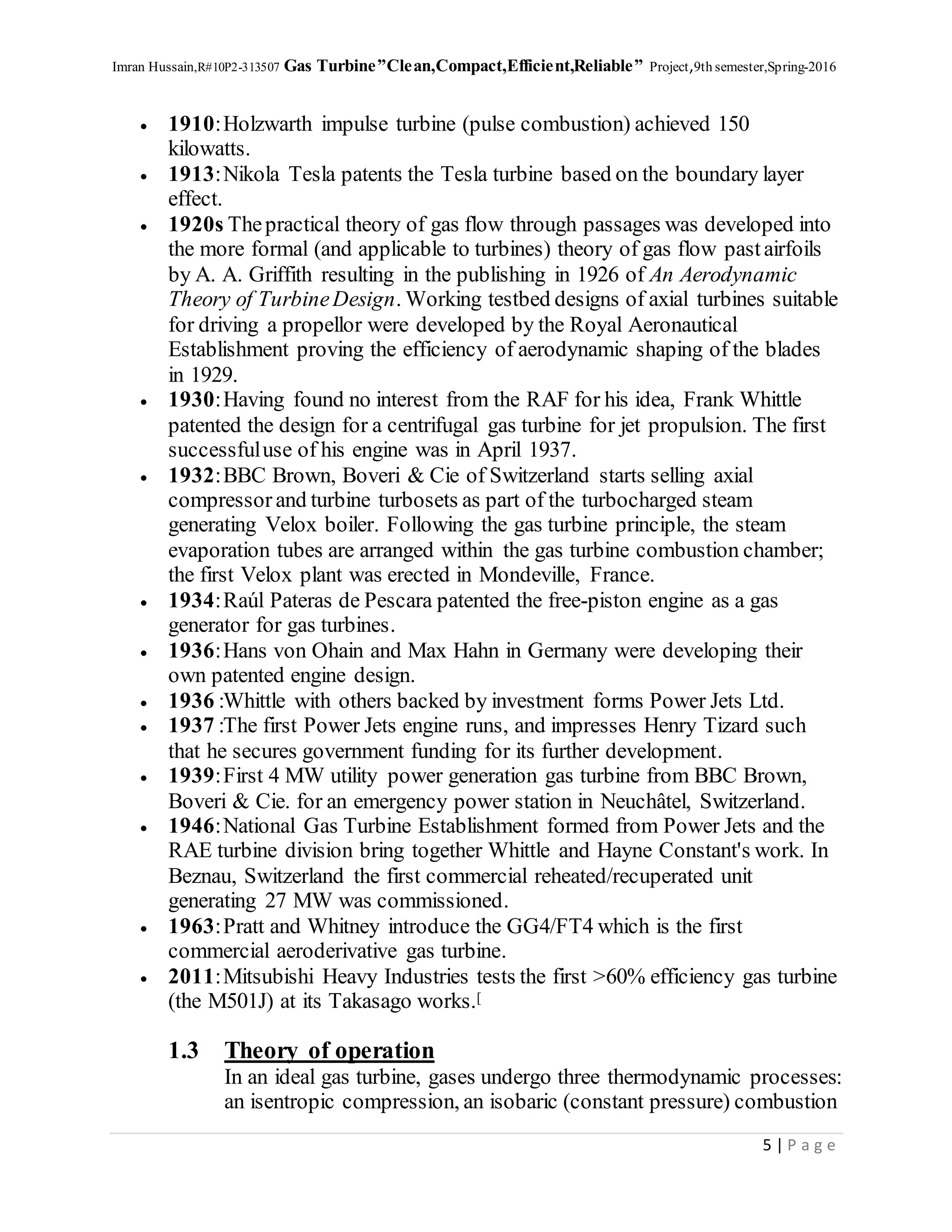
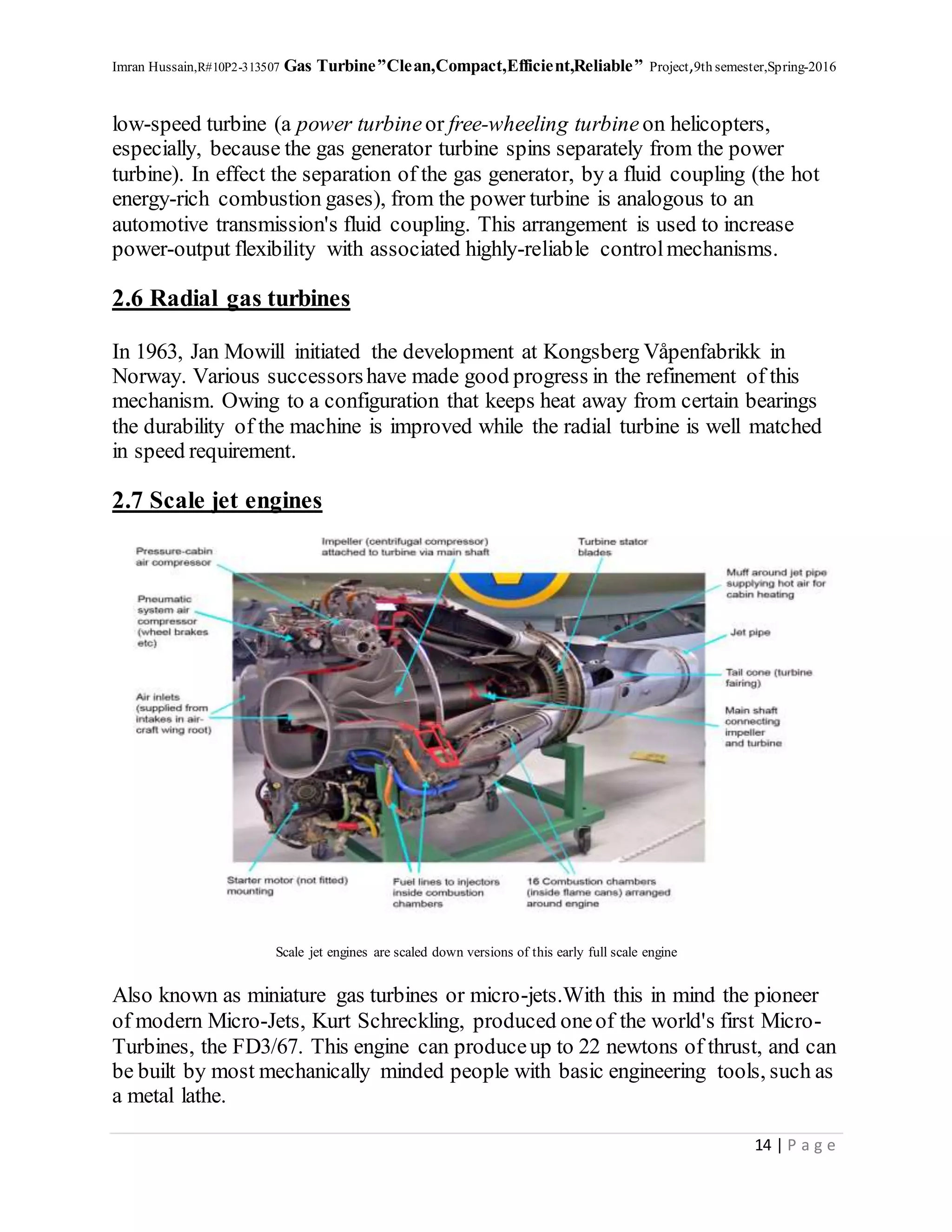
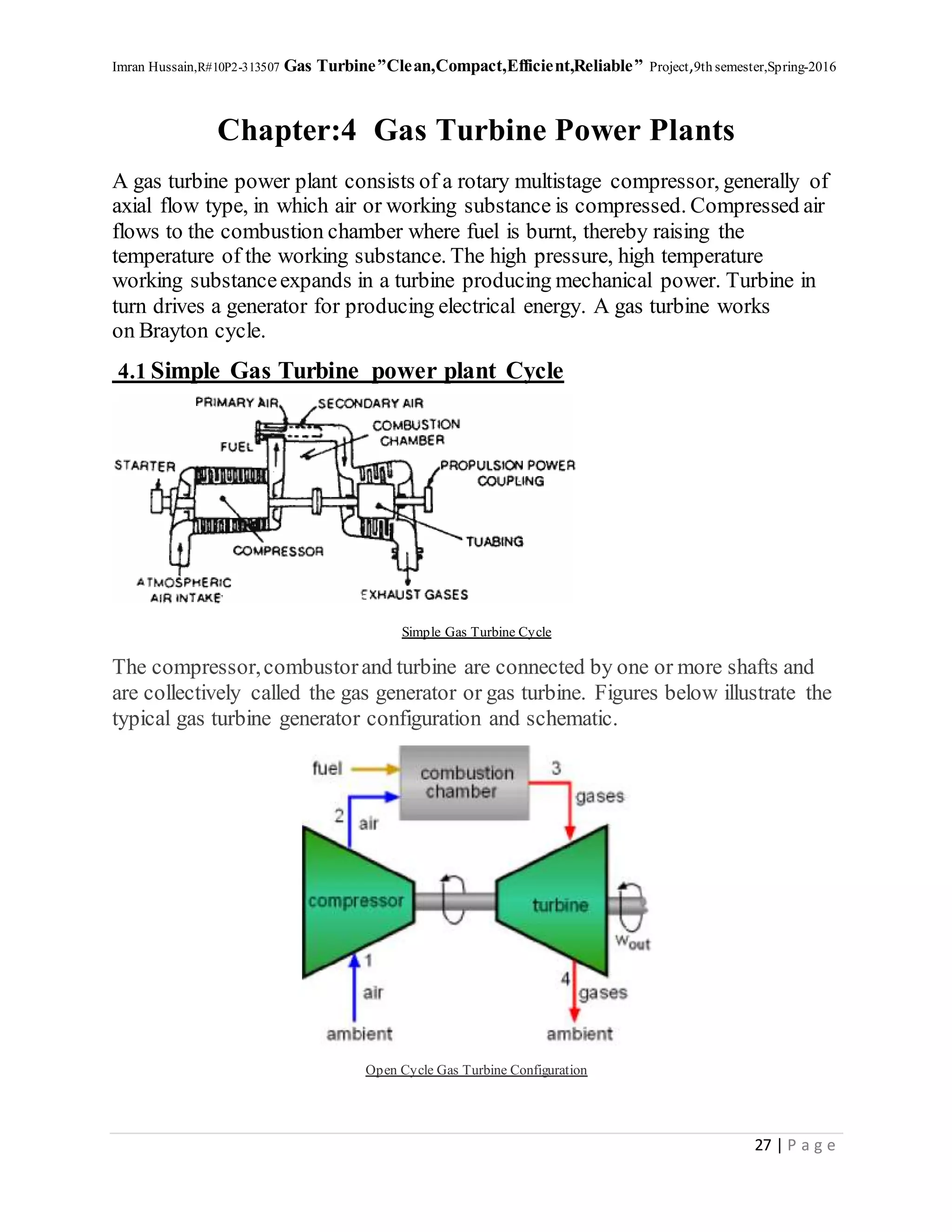
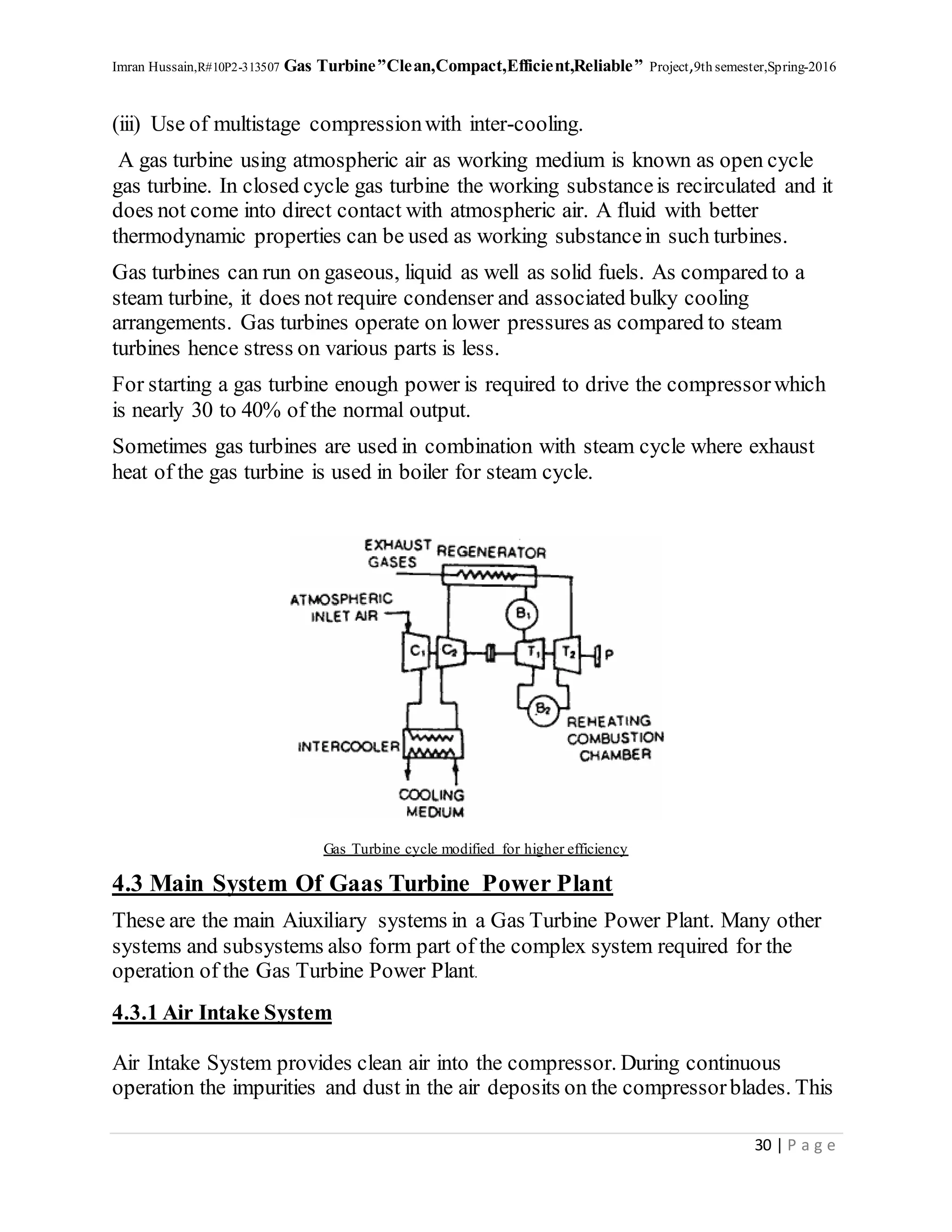
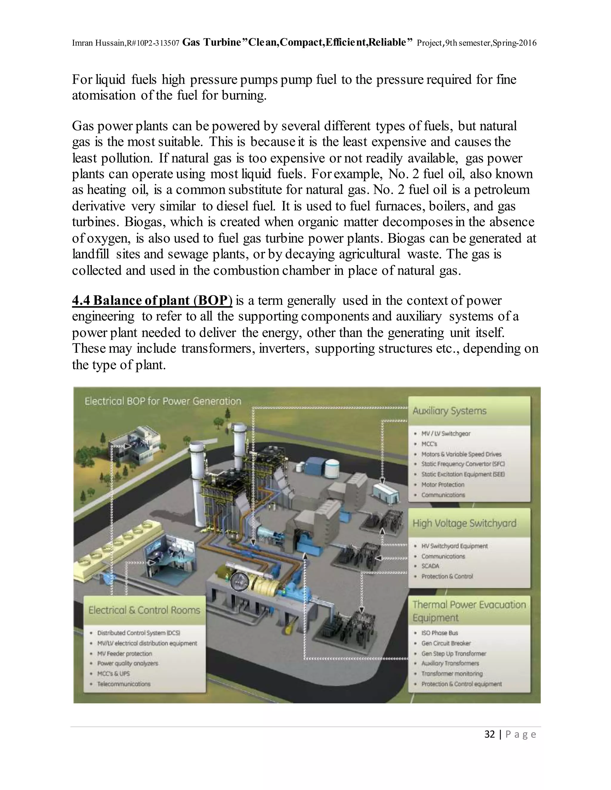
This document contains a chapter on the basics of gas turbines. It defines gas turbines and describes their basic operation and history. The key components of a gas turbine include a compressor, combustion chamber, and turbine. Air is compressed in the compressor then mixed with fuel and ignited in the combustion chamber. The hot exhaust gases pass through the turbine, which drives the compressor and generates power. The history section traces the development of gas turbines back to inventions in ancient times and discusses important milestones in the 19th-20th centuries.
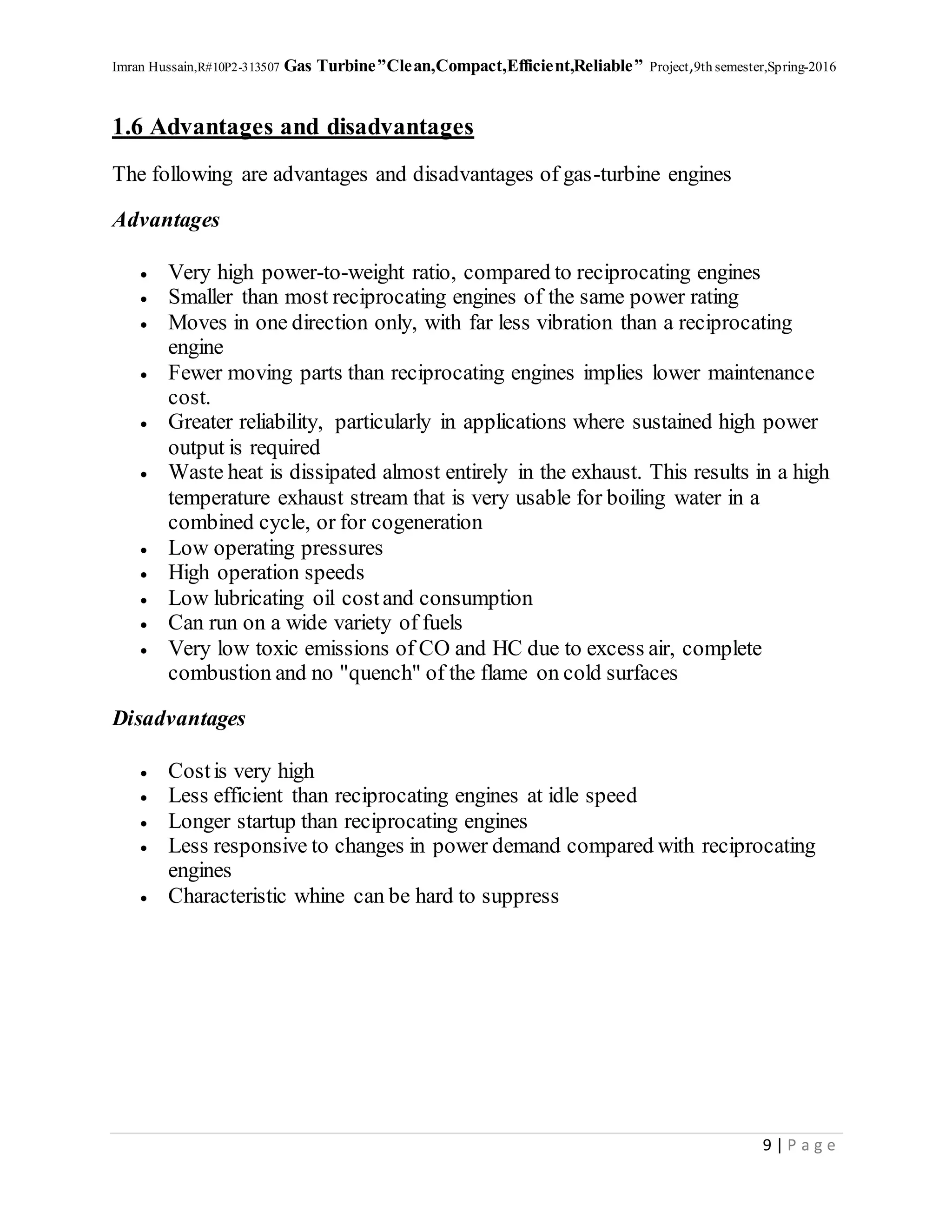
This document summarizes a presentation about the Kota Super Thermal Power Station in India. It describes that the power station was established in 1973 along the Chambal River and has a total generation capacity of 1,240MW from its 7 units. The power station uses coal as its fuel, which is pulverized and burned to convert water into high-pressure steam that drives turbines connected to generators. The station employs various processes and equipment to handle coal, produce steam, generate electricity, treat water, and dispose of ash in an environmentally-safe manner. It provides a valuable practical training opportunity for engineering students to learn about large-scale power generation.
SUMMER INTERNSHIP(INDUSTRAIL REPORT) ON THERMAL POWER PLANT Amit Gupta
The document describes the key components and processes involved in a typical coal-fired thermal power plant, including coal handling, pulverizing, combustion in the boiler, steam generation, power generation in the turbine, and condensing spent steam. It also provides details on equipment like draft fans, superheaters, reheaters, the ash handling system, feedwater heaters, and installed capacity of thermal power plants in Rajasthan.
1. A gas turbine uses a gaseous working fluid that is compressed in a compressor, heated in a combustion chamber, and expanded through a turbine to produce mechanical power.
2. Early gas turbines had low efficiency but could start quickly, so they were used to provide peak power loads. Improved materials and cooling techniques have increased efficiency over time.
3. The ideal gas turbine cycle is known as the Joule-Brayton cycle and consists of isentropic compression, constant pressure heating, isentropic expansion, and isobaric closure back to the initial state.
The Thermal Power Station burns fuel & uses the resultant to make the steam, which derives the turbo generator. The Fuel i.e. coal is burnt in pulverized from. The pressure energy of the steam produce is converted into mechanical energy with the help of turbine. The mechanical energy is fed to the generator where the magnet rotate inside a set of stator winding & thus electricity is produced in India 65% of total power is generated by thermal power stations. To understand the working of the Thermal Power Station plant, we can divide the whole process into following parts.
Energy performance assessment of boilersUtsav Jain
The document discusses performance testing of boilers. It describes various factors that affect boiler performance over time such as poor combustion, heat transfer fouling, and deteriorated fuel and water quality. Boiler efficiency testing is important to evaluate how efficiency changes from the design value and identify problems. The direct method and indirect method of testing are described. The indirect method involves calculating different heat losses in the boiler system to determine efficiency. Various measurements, instruments, test conditions and computational procedures for conducting boiler performance tests are outlined.
The document provides an overview of the Panipat Thermal Power Station located in Haryana, India. It discusses the key elements of a thermal power station including coal handling, the steam generation process, turbines, generators, condensers, cooling towers and switchyards. The power station uses coal to produce steam that drives turbines connected to generators to produce 1367.7 MW of electricity for Haryana. In conclusion, it notes that Panipat Thermal is the largest power plant in Haryana.
Gas turbines work by compressing air, mixing it with fuel, and igniting the mixture to produce hot gases. These gases are used to spin a turbine, generating mechanical power. There are two main types - open cycle plants which exhaust gases to the atmosphere, and closed cycle plants which circulate working fluid. Gas turbines find application in aviation, power generation, and marine propulsion due to their compact size and ability to use various fuels.
Gas turbine plants use compressed air and combustion to drive a turbine and generate power. They have high efficiency, quick start-up times, and can use different fuels. The key components are an air compressor, combustor, and turbine connected by a common shaft. Air is compressed then mixed with fuel and ignited in the combustor. The hot gases drive the turbine which powers the compressor and generator. Axial compressors are commonly used due to their ability to deliver large air volumes at moderate pressures.
This document discusses gas turbines, including their components and how they work. It describes the key components - compressors, combustors, and turbines - and explains the basic Brayton cycle of compression, combustion, and expansion that produces power. It also covers gas turbine applications in aircraft engines and industrial settings, and discusses performance factors like efficiency and output over varying operating conditions.
A gas turbine uses a gaseous working fluid to generate mechanical power that can power industrial devices. It has three main parts - an air compressor, combustion chamber, and turbine. The air is compressed in the compressor, mixed with fuel and ignited in the combustion chamber, and the hot gases spin the turbine to generate power. Some applications of gas turbines include aviation, power generation, and the oil and gas industry. The efficiency of gas turbines is typically 20-30% compared to 38-48% for steam power plants.
A gas turbine power plant works by compressing air which is then mixed with fuel and ignited in a combustion chamber. This produces hot gases that spin a turbine, generating power. The key components are the compressor, combustion chamber, and turbine. The compressed air and added fuel are burned in the combustion chamber. This turns the turbine, powering the compressor and external loads. Gas turbines are used for power generation and to drive aircraft, ships, pumps and other machinery.
The document provides data on steam flows, pressures, and temperatures at the inlet, extraction, and condensing sections of a turbine. It then calculates the efficiencies of the extraction and condensing sections. For the extraction section, it calculates the inlet steam enthalpy, extraction steam enthalpy and entropy, and isentropic extraction steam enthalpy. Using these values, it determines the extraction section efficiency is 67%. For the condensing section, it states efficiency will be calculated but does not show the calculation.
Gas turbines work by compressing air in a compressor, combusting fuel in a combustion chamber which increases the temperature and pressure of the air, and driving a generator with the mechanical energy produced by expanding the hot gas in a turbine. Key components include the compressor, combustion chamber, and turbine mounted on a common shaft. Gas turbines were first developed in the early 20th century and are now used widely in power plants due to their ability to respond quickly to changing demand. Advantages include quick construction time and lower fuel storage needs, while disadvantages include lower efficiency compared to steam plants.
This document discusses knocking combustion in internal combustion engines. It defines knocking combustion as abnormal combustion in the combustion chamber that leads to a sudden pressure rise and hammering sound, resulting in reduced performance and potential engine damage. It then discusses the causes and effects of knocking in spark ignition (SI) engines and compression ignition (diesel) engines. Some of the key factors that influence knocking include fuel type, compression ratio, ignition timing, and air-fuel ratio. The document also covers related topics like octane rating, cetane rating, and strategies to prevent knocking.
This document discusses properties of coal that are important for combustion, including swelling index, grindability, weatherability, sulfur content, heating value, and ash softening temperature. It then covers different methods of coal firing in steam power plants, including hand firing, stoker firing (overfeed and underfeed systems), and pulverized coal firing. Key advantages and disadvantages of different stoker types like chain grate, spreader, single retort, and multi-retort stokers are highlighted.
This document summarizes a study of a diesel engine power plant. It describes how a diesel engine is used as the prime mover to generate mechanical energy through combustion, which is then converted to electrical energy by an alternator. Diesel power plants are efficient and economical for small-scale power generation, especially where other fuel sources are not available or load factors are high. The document outlines the objectives, components, operating principles, applications and types of diesel engines used in diesel power plants.
Ntpc (national thermal power corporation) sipat mechanical vocational trainin...haxxo24
This document is a vocational training report submitted by Ritesh Patnaik after completing a 30-day training at the National Thermal Power Corporation plant in Sipat, Chhattisgarh, India. The report provides an overview of the key components and systems at the NTPC Sipat Super Thermal Power Project, including the steam turbine, generator, condenser, boiler, cooling towers, and pollution control devices. It also describes the basic Rankine cycle that is used to convert heat into electrical power at thermal power plants.
The document discusses the Stirling engine, an external combustion engine invented in 1816 by Robert Stirling as a safer alternative to steam engines. It works by alternately compressing and expanding a gas with temperature differences created between the hot and cold sections. Key advantages are its ability to run on various heat sources, its safety compared to steam, and lower environmental impact. Applications include power generation, heating, cooling, and more. The document outlines the history, components, working principles, types, advantages, applications and conclusion of the Stirling engine as a sustainable technology.
The document summarizes an internship report on analyzing the air compressor at an LPG bottling plant in Budge Budge, India. It describes the plant's production of filling 1200 cylinders per day. It also outlines the plant's storage facilities including bullet tanks and cylinders. Safety procedures for loading/unloading tankers are explained. The document also provides details on the pump house, compressor operation, and safety equipment used.
The document summarizes the key components and mechanisms of a coal-based thermal power plant. The plant works on the basic Rankine cycle where coal is burned to produce steam that drives a turbine connected to a generator, producing electricity. The main components are the boiler, steam turbine, condenser, pumps, heaters, and other ancillary equipment. Coal is burned in the boiler to heat water and produce high-pressure steam to spin the turbine, which drives the generator and produces electricity. After working the turbine, the steam is condensed in the condenser and recycled to the boiler to repeat the process.
Effect of Coal Quality and Performance of Coal pulverisers / MillsManohar Tatwawadi
The presentation discusses about the change in performance parameters of a pulveriser due to change in coal quality and the measurement of performance and troubleshooting of coal firing system as a whole.
The document provides information on assessing the energy performance of boilers through testing. It discusses how boiler efficiency and evaporation ratio can decrease over time due to various factors like poor combustion, fouling, and deteriorating fuel/water quality. The purpose of performance testing is to determine the actual efficiency and compare it to design values in order to identify areas for improvement. Both direct and indirect testing methods are described as well as the necessary measurements, instruments, standards, and considerations involved in conducting the tests. Formulas are also provided for calculating efficiency using the indirect method by establishing heat losses from the boiler.
This document discusses the calculation of heat rate and turbine cylinder efficiency for a 210 MW KWU turbine cycle. It describes the enthalpy method used to calculate heat rate, which involves measuring steam and flow parameters at various points and using steam tables to determine enthalpy values. The calculation is done in four parts: measurements, enthalpy calculations, determining hot reheat flow, and the final heat rate calculation. Turbine cylinder efficiency is also calculated using enthalpy drop methods by determining actual and theoretical enthalpy changes across the high pressure turbine. Standard methods and typical heat rates for different capacity turbines are also listed.
NTPC was established in 1975 by the Government of India to address growing power demand. It is now the largest power generating company in India with over 30 GW of installed capacity from coal, gas, hydro, and renewable sources. NTPC started with thermal power plants and has expanded into various power generation technologies and business areas. The document provides details on NTPC's thermal power plants across India, including their locations and installed capacities.
This document discusses gas turbines, including their basic components and working principle. A gas turbine combusts fuel in the presence of compressed air, converting the thermal energy of the combustion products into mechanical energy. The main components are the compressor, combustion chamber, and turbine. The compressed air is mixed with fuel and burned in the combustion chamber. The hot gases then power the turbine before being exhausted. Gas turbines have applications in vehicles, aircraft, ships, and power generation.
This document describes the key components and processes involved in a thermal power plant. Water is heated to produce steam, which spins turbines connected to generators to produce electricity. The main components are the boiler, turbines, condenser, cooling tower and auxiliary systems. Coal is pulverized and burned in the boiler to heat water and produce high pressure steam. The steam powers high, intermediate and low pressure turbines in succession to generate electricity before being condensed back into water in the condenser. The water is cooled in the cooling tower and recycled to the boiler to repeat the process.
Gas turbines have three main parts - an air compressor, combustion chamber, and turbine. The air compressor increases the pressure of air that is mixed with fuel in the combustion chamber and ignited. This powers the turbine, which can generate mechanical power or thrust. There are two main types - open cycle gas turbines that exhaust air to the atmosphere, and closed cycle gas turbines that recirculate the working fluid through a cooler before returning it to the compressor. Methods to improve gas turbine efficiency include intercooling the compressed air between compression stages, reheating the gas before a secondary expansion turbine, and regenerating heat from the exhaust to preheat the incoming compressed air.
The new world energy market is leading more and more toward highly efficient power plants together with the necessity of fulfill new stringent limits for the environmental emissions. We offer Power Plants that show peculiar advantages in this way allowing fuel economisation through the exploitation of the flue gas heat thermal power produced by the gas turbine upper cycle in a bottom steam cycle, a larger range of flexibility strategies for power production, an optimisation of the whole plant efficiency and a limited environmental impact.
Craig & Rupert Denis Limited, a distinguished player in the energy industry, providing reliable and flexible solutions across a complete and innovative product portfolio in the power generation field: equipment and plant design, engineering, manufacturing, contracting, service and customer assistance.
We are international turn-key power plant provider designing and manufacturing several plant types: thermal, geothermal, combined cycle, cogeneration and many activities for nuclear power plants. According to the market demand, the core business focuses on combined cycle power plants supplied n a wide range of generating capacities from 100 to1,600 MW.
This document is a chapter from a student project on photovoltaic solar power plants. It includes an introduction to PV solar technology that discusses grid-connected and off-grid PV systems, solar cell types, conversion efficiency, and factors affecting PV performance. It also provides details on the major components of a PV plant such as electrical buildings, inverters, DC systems, modules and arrays. The appendices include examples of annual power generation and CO2 reduction from solar as well as a glossary of solar terms.
The document outlines the professional approach and core values of integrity, respect, collaboration, empowerment and responsibility. It then lists the industries served, including mega construction projects, hospitality, healthcare, oil and gas, manufacturing, power and utility, engineering procurement and construction, mining, IT and telecommunications, and operation and maintenance. Key services provided are ensuring confidentiality, having a global reach, customer satisfaction, quality project delivery, development process support, and daily status updates.
This document provides summaries of five case studies of successful not-for-profit dental centers across the United States. Common lessons learned from the centers include implementing strategies for economies of scale, focusing on specific patient populations, developing partnerships, utilizing dental residents, finding committed providers, quality improvement programs, engaging leadership and boards, attention to financial sustainability, and the importance of scaling operations for efficiency. The case studies highlight centers ranging in size and revenue that have found ways to expand access to care while remaining financially viable through various strategies.
The feedback was regarding a magazine cover and film poster design. The designs needed some adjustments to better communicate the intended messages. Specifically, the magazine cover photo did not clearly convey the article's topic and the film poster text was too small and busy. Suggestions were provided to select a more relevant photo and simplify the poster design.
OneDrive is a free online file storage service that allows users to store and access files from any device. Files can be added to OneDrive from a computer by dragging them into the OneDrive folder, from a phone or tablet using the OneDrive app, or from any device using the OneDrive website. Once files are in OneDrive, they can be easily shared or collaborated on with others. OneDrive also integrates with Windows and Office programs to allow files to be accessed and edited from any device.
Nandan Lorekar is seeking a position that utilizes his 2.6 years of experience in roles such as computer operator, HR executive, and administrator. He has strong skills in Microsoft Office, problem solving, multi-tasking, and time management. His resume provides details on his work history and responsibilities in previous roles supporting HR, administration, and computer operations.
This document discusses age ratings and certifications for movies in the US and UK. It provides examples of how two movies, Copycat and Single White Female, received R ratings from the MPAA for violence, language and sexuality. It also explains that the BBFC and MPAA help determine age ratings and content descriptions to help parents decide if a film is suitable for their children. The document concludes that the creator's movie would be rated 15 by the BBFC due to its strong violence, language, sexual content and references to sex and violence.
This short document promotes creating presentations using Haiku Deck on SlideShare. It encourages the reader to get started making their own Haiku Deck presentation by providing a button to click to begin the process. The document is advertising the creation of presentations on Haiku Deck and SlideShare.
This short document promotes the creation of Haiku Deck presentations on SlideShare and provides examples of stock photos that could be used from photographers blmiers2, f"lish kamina, Alexey Kljatov (ChaoticMind75), and Martin Gommel. It encourages the reader to get started making their own Haiku Deck presentation.
This document provides strategies for choosing a major, including completing written exercises to reflect on interests and goals, asking the right questions about potential majors, researching majors through the university catalog and talking to current students, gaining experience through coursework, job shadowing or internships, and exploring careers through assessments at the Career Services office. It notes that about 1/3 of college students enter undeclared and over 50% change majors. The final steps are meeting with an advisor in the chosen major and completing a declaration of major form.
This document provides an overview of using audio test and measurement instruments to evaluate broadcast facilities. It discusses using multitone signals to test audio quality over the air and evaluate new equipment in real time. Case studies are presented on using audio analyzers to diagnose issues with a Bluetooth car kit by measuring speech quality scores and analyzing frequency response characteristics. The document emphasizes the importance of objective measurement for ensuring broadcast audio quality.
The document describes the author's experience as a counselor for JOLT, a summer camp program in Ukraine. She was asked to teach local children about Judaism through classes, activities, and by being a role model. Though there was a language barrier, the author formed strong bonds with the children, especially a boy named Glieb who was deeply engaged in learning Hebrew. On the last day of camp, they exchanged gifts - the boy gave her a keychain while she gifted her prayer book, which deeply moved both of them. The experience had a profound impact on the author and shaped her desire to continue helping others through her career in nursing.
Kundan Kumar Singh is a civil engineer with over 4 years of experience in construction field, quality control, and project management. He is looking for a new opportunity to utilize his skills and knowledge. He has experience in planning, monitoring, resource allocation, quality assurance, and supervision of projects. He also has technical skills in estimation, design, AutoCAD, and conducting lab tests. His most recent role was as Quality Control Engineer at Jindal SAW Limited.
Fiama Di Wills targets young, modern, skin-conscious people between 18-35 years old. It segments the market based on age, lifestyle, and priorities. Fiama Di Wills positions itself as a high-quality, affordable soap that provides moisture and care for the skin, appealing to middle-class men and women seeking everyday skin care products. The gel soap bar contains conditioners for rich moisturization at an accessible price point.
CloudEngage Powering the Geo-Responsive WebTom Williams
Personalization should start with the first visit to your site, but it has to be fast and lightweight or it just won't get used.
CloudEngage geolocation offers super easy personalization with custom content based on location of each viewer and local weather. 91% of marketers can't be wrong.
How do you Cool Your Brew? Cool Brewing Fermentation CoolerCool-brewing
This short document shares 4 photos from different photographers to inspire creativity. It encourages the viewer to create their own presentation on SlideShare using Haiku Deck, a tool for making simple slideshows. A brief call to action is given to get started making a presentation.
Jabu Sithole is an accounts professional seeking a new opportunity. He has over 15 years of experience in accounting roles of increasing responsibility. His most recent role was as Debtors and Creditors Controller where he performed all accounting functions for two subsidiaries, including bank reconciliations, statutory reporting, and monthly management accounts. He has expertise in accounting software like Pastel and seeks to continue developing his skills in a stable position.
The document discusses the benefits of exercise for mental health. Regular physical activity can help reduce anxiety and depression and improve mood and cognitive function. Exercise causes chemical changes in the brain that may help protect against mental illness and improve symptoms.
The gas turbine is an internal combustion engine that uses air as the working fluid. The engine extracts chemical energy from fuel and converts it to mechanical energy using the gaseous energy of the working fluid (air) to drive the engine and propeller, which, in turn, propel the airplane.
The document describes the design and applications of different types of turbines. It provides an overview of the history and development of turbines, including early steam turbines invented by de Laval and Parsons. It then classifies turbines into categories such as hydraulic, steam, gas, and wind turbines. For each type, it discusses the basic theory of operation, examples, and efficiency. Hydraulic turbines are further divided into reaction and impulse types with examples like the Francis, Kaplan, and Pelton turbines. The document aims to inform about the different designs and uses of turbines.
Steam turbines are highly efficient machines that convert the heat energy from fossil and nuclear fuels into kinetic energy, primarily used to generate electricity and propel large ships. They work by directing high-pressure steam through successive rows of rotating and stationary blades, transferring the steam's thermal energy into rotational motion. Modern steam turbines can be over 1,300 megawatts in size and generate over 50,000 megawatts of power worldwide each year, demonstrating their importance as a means of power production.
1) The document provides a history of the development of gas turbine engines from early concepts like Hero of Alexandria's aeolipile in the 1st century to modern trends.
2) Key developments included Frank Whittle's patent for a gas turbine engine in 1930 and the first flight of a jet-powered aircraft by Germany in 1939.
3) Modern gas turbine engines are classified based on their compressor type and power usage, including turbojet, turbofan, turboprop, and turboshaft engines used in aviation and other industries.
This document is a technical seminar report submitted by a student to fulfill requirements for a Bachelor of Technology degree in Mechanical Engineering. The report discusses the history and working principles of steam turbines, including their advantages and disadvantages. It describes different types of steam turbines such as impulse and reaction turbines. It also covers topics like compounding, steam supply and exhaust conditions, turbine components, operation principles, applications, and thermodynamics of steam turbines. The document contains detailed information presented over multiple sections and references.
1) The document discusses gas turbine engines, which are used to power commercial jets, helicopters, tanks, and power plants. They work by compressing air, mixing it with fuel, igniting it to create hot gases, and using those expanding gases to power turbines and produce thrust or rotation.
2) Engineering advancements in the early 1900s led to the development of gas turbines. They revolutionized airplane propulsion in the 1940s and have since been used for power generation and ships.
3) While powerful and compact, gas turbines are also expensive to design and manufacture due to their high operating temperatures and speeds. They consume more fuel when idling and prefer constant loads.
This document provides an overview of gas turbine engines. It discusses the history of gas turbine engines, including early developments in England, Germany, and the United States. It then describes the basic process of how gas turbine engines work, including the compressor, combustion chamber, and turbine. Finally, it discusses the different types of gas turbine engines, such as centrifugal flow, axial flow, and centrifugal-axial flow engines.
This document is a seminar presentation on superchargers vs turbochargers. It includes:
- An introduction comparing superchargers and turbochargers as ways to force more air into an engine to increase power.
- Sections on the history, working principles, and types of both superchargers and turbochargers. Common types include roots, twin screw, and centrifugal superchargers as well as single and twin turbochargers.
- Diagrams and images are included to illustrate the components and function of different supercharger and turbocharger designs.
The document provides an introduction to compressed air engines. It discusses how compressed air engines store compressed air in tanks and use the expansion of the air to drive pistons, instead of fuel combustion. The document then reviews the history of compressed air vehicles from 1828 to the 1870s. It also describes the key components of compressed air engines, including compressors, air tanks, valves, pistons, connecting rods, and crankshafts. The crankshaft and camshaft components are explained in more detail.
This document provides information about a seminar report on gas turbine engines submitted by Sahilesh D. Pol. It includes an approval sheet signed by his guide and department head. The introduction acknowledges those who helped with the report. The abstract states that the report will cover the working process, types and applications of gas turbine engines as well as their advantages over reciprocating engines. The document contains sections on history, types of gas turbine engines including centrifugal, axial and centrifugal-axial flow, engine theory, and advantages/disadvantages.
This document provides an introduction to air powered engines. It discusses how air powered engines work by using compressed air stored in high-pressure tanks to drive pistons or turbines, instead of combusting fuel. The key components of an air powered engine system are the compressed air engine itself, high-pressure air storage tanks made of materials like steel or carbon fiber, and an onboard air compressor to refill the tanks. Some advantages mentioned are that air powered engines have fewer emissions and parts than internal combustion engines.
Gaz türbinli motorların tarihçesi ve sınıflandırılmasıMete Cantekin
The document provides a history of the development of various aerospace engine technologies from ancient times to modern day, including key inventors and innovations. It begins with early concepts like Hero's steam engine in 150 AD and progresses to important milestones like Whittle's 1930 patent for the gas turbine jet engine. The document also classifies different types of airbreathing and non-continuous combustion engines and discusses some future propulsion technologies.
The document discusses the history and design of compressed air engines. It provides details on the development of compressed air vehicles from the 19th century to present day, including early prototypes and modern designs. The engine design uses compressed air storage tanks and pistons to capture ambient heat and achieve efficient non-adiabatic expansion. Storage of compressed air poses challenges around cooling and heating during compression/expansion cycles.
This document provides an overview of different types of turbines used for energy conversion. It discusses steam turbines, which are used in power plants to convert the energy of high pressure steam into mechanical power. It describes impulse and reaction steam turbines and examples of each. It also discusses gas turbines, which produce pressurized gas by burning fuel and use the high-speed rush of hot air to spin a turbine, and are used to produce large quantities of power compactly. Finally, it briefly mentions wind turbines which similarly convert the kinetic energy of wind into mechanical power.
Rocket engines produce thrust by accelerating and ejecting stored propellants at high speeds through a nozzle. They obtain high thrust-to-weight ratios but have the lowest fuel efficiency of all jet engines. Key components include the combustion chamber, where propellants combust at high pressures and temperatures, and the supersonic nozzle, which converts the hot gas energy into kinetic energy of the exhaust jet for propulsion. Rocket performance is optimized by maximizing exhaust velocity and specific impulse through high combustion temperatures, low-mass propellants, and nozzle designs that adapt to changing ambient pressures.
This document summarizes the working of Stirling engines. It discusses how Stirling engines operate based on the Stirling thermodynamic cycle, with isothermal expansion and compression processes. The key components of Stirling engines are described, including the heat source, regenerator, heat sink, displacer piston, and power piston. The document outlines the history and development of Stirling engines. It provides examples of applications for Stirling engines such as solar power generation, cooling, and pumping. In conclusion, Stirling engines are described as simple, versatile devices that can harness various heat sources for energy conversion in a reliable manner.
The document provides an introduction to compressed air vehicles and air cars. It discusses the history of compressed air technology dating back to the late 19th century when the first pneumatic locomotives were developed. It then describes Tata Motors' plans to introduce the MiniCAT, the world's first commercial air-powered vehicle, in India by 2012. The MiniCAT would be powered by compressed air stored in carbon fiber tanks at high pressure and cost around $8,177. It would have a range of 300km between refuels and refueling would cost approximately $2. The document then discusses the basic working principles of compressed air technology and air cars, which use compressed air expanded through pistons to power the vehicle.
Four-Stroke and Two-Stroke Marine Engines Comparison and ApplicationIJERA Editor
The document compares four-stroke and two-stroke marine engines. It provides details on the history and development of different marine engine types over time, from early propulsion relying on wind and oars to modern internal combustion engines. The four-stroke engine cycle includes intake, compression, power, and exhaust strokes within two revolutions of the crankshaft. The two-stroke engine completes the intake, compression, power, and exhaust steps within one revolution, making it more efficient but also risking exhaust of unburned fuel. Marine vessels favor two-stroke engines due to better fuel usage, efficiency, and power-to-weight ratio compared to four-stroke engines.
Four-Stroke and Two-Stroke Marine Engines Comparison and Application
Gas Turbine project
1. Imran Hussain,R#10P2-313507 Gas Turbine”Clean,Compact,Efficient,Reliable” Project,9th semester,Spring-2016
1 | P a g e
Gas Turbine Power
CLEAN,COMPACT, EFFICIENT, RELIABLE
Project,9th Semester(Summer),2016
B Tech(Hons),Electrical
Preston University,Islamabad
Imran Hussain
R#10P2-313507
2. Imran Hussain,R#10P2-313507 Gas Turbine”Clean,Compact,Efficient,Reliable” Project,9th semester,Spring-2016
2 | P a g e
Contents
Chapter:1 Baiscof Gas Turbine
Chapter:2 Types of Gas Turbine
Chapter:3 Special,Automobile and Heavy Use Of
Gas Turbines
Chapter:4 Gas Turbine Power Plants
Chapter:5 Gas Turbine Power Plants in
Pakistan
3. Imran Hussain,R#10P2-313507 Gas Turbine”Clean,Compact,Efficient,Reliable” Project,9th semester,Spring-2016
3 | P a g e
Chapter:1 Basic of Gas Turbine
1.1 Defination
A turbine driven by expanding hot gases produced byburning fuel, as in a jet
engine
A gas turbine, also called a combustion turbine, is a type of internal combustion
engine. It has an upstream rotating compressor coupled to a downstream turbine,
and a combustionchamber in between.
The basic operation of the gas turbine is similar to that of the steam power plant
except that air is used instead of water. Fresh atmospheric air flows through a
compressorthat brings it to higher pressure. Energy is then added by spraying fuel
into the air and igniting it so the combustion generates a high-temperature flow.
This high-temperature high-pressure gas enters a turbine, where it expands down to
the exhaust pressure, producing a shaft work output in the process. Theturbine
shaft work is used to drive the compressorand other devices such as an electric
generator that may be coupled to the shaft. The energy that is not used for shaft
work comes out in the exhaust gases, so these have either a high temperature or a
high velocity. The purposeof the gas turbine determines the design so that the
most desirable energy form is maximized. Gas turbines are used to power aircraft,
trains, ships, electrical generators, and tanks.
1.2 History
Sketch of John Barber's gas turbine, from his patent
50: Hero's Engine (aeolipile) — Apparently, Hero's steam engine was taken
to be no more than a toy, and thus its full potential not realized for centuries.
1000:The "Trotting Horse Lamp" was used by the Chinese at lantern fairs as
early as the Northern Song dynasty. When the lamp is lit, the heated airflow
4. Imran Hussain,R#10P2-313507 Gas Turbine”Clean,Compact,Efficient,Reliable” Project,9th semester,Spring-2016
4 | P a g e
rises and drives an impeller with horse-riding figures attached on it, whose
shadows are then projected onto the outer screen of the lantern.
1500:The "Chimney Jack" was drawn by Leonardo da Vinci: Hot air from a
fire rises through a single-stage axial turbine rotor mounted in the exhaust
duct of the fireplace and turning the roasting spit by gear/ chain connection.
1629:Jets of steam rotated an impulse turbine that then drove a working
stamping mill by means of a bevel gear, developed by Giovanni Branca.
1678:Ferdinand Verbiest built a model carriage relying on a steam jet for
power.
1791:A patent was given to John Barber, an Englishman, for the first true
gas turbine. His invention had most of the elements present in the modern
day gas turbines. The turbine was designed to power a horseless carriage.
1861:British patent no. 1633 was granted to Marc Antoine Francois
Mennons for a "Caloric engine". The patent shows that it was a gas turbine
and the drawings show it applied to a locomotive. Also named in the patent
was Nicolas de Telescheff (otherwise Nicholas A. Teleshov), a Russian
aviation pioneer.
1872:A gas turbine engine was designed by Franz Stolze, but the engine
never ran under its own power.
1894:Sir Charles Parsons patented the idea of propelling a ship with a steam
turbine, and built a demonstration vessel, the Turbinia, easily the fastest
vessel afloat at the time. This principle of propulsion is still of some use.
1895:Three 4-ton 100 kW Parsons radial flow generators were installed in
Cambridge Power Station, and used to power the first electric street lighting
scheme in the city.
1899:Charles GordonCurtis patented the first gas turbine engine in the
USA ("Apparatus for generating mechanical power", Patent No.
US635,919).
1900:Sanford Alexander Moss submitted a thesis on gas turbines. In 1903,
Moss became an engineer for General Electric's Steam Turbine Department
in Lynn, Massachusetts. While there, he applied some of his concepts in the
development of the turbosupercharger. His design used a small turbine
wheel, driven by exhaust gases, to turn a supercharger.
1903:A Norwegian, Ægidius Elling, was able to build the first gas turbine
that was able to producemore power than needed to run its own
components, which was considered an achievement in a time when
knowledge about aerodynamics was limited. Using rotary compressorsand
turbines it produced 11 hp (massive for those days).
1906:The Armengaud-Lemale turbine engine in France with water-cooled
combustion chamber.
5. Imran Hussain,R#10P2-313507 Gas Turbine”Clean,Compact,Efficient,Reliable” Project,9th semester,Spring-2016
5 | P a g e
1910:Holzwarth impulse turbine (pulse combustion) achieved 150
kilowatts.
1913:Nikola Tesla patents the Tesla turbine based on the boundary layer
effect.
1920s Thepractical theory of gas flow through passages was developed into
the more formal (and applicable to turbines) theory of gas flow pastairfoils
by A. A. Griffith resulting in the publishing in 1926 of An Aerodynamic
Theory of TurbineDesign. Working testbed designs of axial turbines suitable
for driving a propellor were developed by the Royal Aeronautical
Establishment proving the efficiency of aerodynamic shaping of the blades
in 1929.
1930:Having found no interest from the RAF for his idea, Frank Whittle
patented the design for a centrifugal gas turbine for jet propulsion. The first
successfuluse of his engine was in April 1937.
1932:BBC Brown, Boveri & Cie of Switzerland starts selling axial
compressor and turbine turbosets as part of the turbocharged steam
generating Velox boiler. Following the gas turbine principle, the steam
evaporation tubes are arranged within the gas turbine combustion chamber;
the first Velox plant was erected in Mondeville, France.
1934:Raúl Pateras de Pescara patented the free-piston engine as a gas
generator for gas turbines.
1936:Hans von Ohain and Max Hahn in Germany were developing their
own patented engine design.
1936 :Whittle with others backed by investment forms Power Jets Ltd.
1937 :The first Power Jets engine runs, and impresses Henry Tizard such
that he secures government funding for its further development.
1939:First 4 MW utility power generation gas turbine from BBC Brown,
Boveri & Cie. for an emergency power station in Neuchâtel, Switzerland.
1946:National Gas Turbine Establishment formed from Power Jets and the
RAE turbine division bring together Whittle and Hayne Constant's work. In
Beznau, Switzerland the first commercial reheated/recuperated unit
generating 27 MW was commissioned.
1963:Pratt and Whitney introduce the GG4/FT4 which is the first
commercial aeroderivative gas turbine.
2011:Mitsubishi Heavy Industries tests the first >60% efficiency gas turbine
(the M501J) at its Takasago works.[
1.3 Theory of operation
In an ideal gas turbine, gases undergo three thermodynamic processes:
an isentropic compression, an isobaric (constant pressure) combustion
6. Imran Hussain,R#10P2-313507 Gas Turbine”Clean,Compact,Efficient,Reliable” Project,9th semester,Spring-2016
6 | P a g e
and an isentropic expansion. Together, these make up the Brayton
cycle.
Brayton cycle
In a real gas turbine, mechanical energy is changed irreversibly (due to
internal friction and turbulence) into pressure and thermal energy when the
gas is compressed (in either a centrifugal or axial compressor). Heat is added
in the combustionchamber and the specific volume of the gas increases,
accompanied by a slight loss in pressure. During expansion through the
stator and rotor passages in the turbine, irreversible energy transformation
once again occurs.
If the engine has a power turbine added to drive an industrial generator or a
helicopter rotor, the exit pressure will be as close to the entry pressure as
possible with only enough energy left to overcome the pressure losses in the
exhaust ducting and expel the exhaust. For a turboprop engine there will be a
particular balance between propeller power and jet thrust which gives the
most economical operation. In a jet engine only enough pressure and energy
is extracted from the flow to drive the compressorand other components.
The remaining high pressure gases are accelerated to provide a jet to propel
an aircraft.
The smaller the engine, the higher the rotation rate of the shaft(s) must be to
attain the required blade tip speed. Blade-tip speed determines the maximum
pressure ratios that can be obtained by the turbine and the compressor. This,
in turn, limits the maximum power and efficiency that can be obtained by
the engine. In order for tip speed to remain constant, if the diameter of a
rotor is reduced by half, the rotational speed must double. Forexample, large
7. Imran Hussain,R#10P2-313507 Gas Turbine”Clean,Compact,Efficient,Reliable” Project,9th semester,Spring-2016
7 | P a g e
jet engines operate around 10,000 rpm, while micro turbines spin as fast as
500,000 rpm.
Mechanically, gas turbines can be considerably less complex than internal
combustion piston engines. Simple turbines might have one main moving
part, the compressor/shaft/turbine rotor assembly (see image above), with
other moving parts in the fuel system. However, the precision manufacture
required for components and the temperature resistant alloys necessary for
high efficiency often make the construction of a simple gas turbine more
complicated than a piston engine.
More advanced gas turbines (such as those found in modern jet engines)
may have 2 or 3 shafts (spools), hundreds of compressorand turbine blades,
movable stator blades, and extensive external tubing for fuel, oil and air
systems.
Thrust bearings and journal bearings are a critical part of design.
Traditionally, they have been hydrodynamic oil bearings, or oil-cooled ball
bearings. These bearings are being surpassed by foil bearings, which have
been successfully used in micro turbines and auxiliary power units.
1.4 Gas Turbine Configuration:
Examples of gas turbine configurations: (1) turbojet, (2) turboprop, (3) turboshaft
(electric generator), (4) high-bypass turbofan, (5) low-bypass afterburning turbofan
8. Imran Hussain,R#10P2-313507 Gas Turbine”Clean,Compact,Efficient,Reliable” Project,9th semester,Spring-2016
8 | P a g e
1.5 Advances in technology
Gas turbine technology has steadily advanced since its inception and continues to
evolve. Development is actively producing both smaller gas turbines and more
powerful and efficient engines. Aiding in these advances are computer based
design (specifically CFD and finite element analysis) and the development of
advanced materials: Base materials with superior high temperature strength (e.g.,
single-crystal superalloys that exhibit yield strength anomaly) or thermal barrier
coatings that protectthe structural material from ever higher temperatures. These
advances allow higher compressionratios and turbine inlet temperatures, more
efficient combustion and better cooling of engine parts.
Computational Fluid Dynamics (CFD) has contributed to substantial improvements
in the performance and efficiency of Gas Turbine engine components through
enhanced understanding of the complex viscous flow and heat transfer phenomena
involved. Forthis reason, CFD is one of the key computational toolused in Design
& development of gas turbine engines.
The simple-cycle efficiencies of early gas turbines were practically doubled by
incorporating inter-cooling, regeneration (or recuperation), and reheating. These
improvements, of course, come at the expense of increased initial and operation
costs, and they cannot be justified unless the decrease in fuel costs offsets the
increase in other costs. Therelatively low fuel prices, the general desire in the
industry to minimize installation costs, and the tremendous increase in the simple-
cycle efficiency to about 40 percent left little desire for opting for these
modifications.
On the emissions side, the challenge is to increase turbine inlet temperatures while
at the same time reducing peak flame temperature in order to achieve lower NOx
emissions and meet the latest emission regulations. In May 2011, Mitsubishi
Heavy Industries achieved a turbine inlet temperature of 1,600 °C on a 320
megawatt gas turbine, and 460 MW in gas turbine combined-cycle power
generation applications in which gross thermal efficiency exceeds 60%.
Compliant foil bearings were commercially introduced to gas turbines in the
1990s. These can withstand over a hundred thousand start/stop cycles and have
eliminated the need for an oil system. The application of microelectronics and
power switching technology have enabled the development of commercially viable
electricity generation by micro turbines for distribution and vehicle propulsion.
9. Imran Hussain,R#10P2-313507 Gas Turbine”Clean,Compact,Efficient,Reliable” Project,9th semester,Spring-2016
9 | P a g e
1.6 Advantages and disadvantages
The following are advantages and disadvantages of gas-turbine engines
Advantages
Very high power-to-weight ratio, compared to reciprocating engines
Smaller than most reciprocating engines of the same power rating
Moves in one direction only, with far less vibration than a reciprocating
engine
Fewer moving parts than reciprocating engines implies lower maintenance
cost.
Greater reliability, particularly in applications where sustained high power
output is required
Waste heat is dissipated almost entirely in the exhaust. This results in a high
temperature exhaust stream that is very usable for boiling water in a
combined cycle, or for cogeneration
Low operating pressures
High operation speeds
Low lubricating oil costand consumption
Can run on a wide variety of fuels
Very low toxic emissions of CO and HC due to excess air, complete
combustion and no "quench" of the flame on cold surfaces
Disadvantages
Costis very high
Less efficient than reciprocating engines at idle speed
Longer startup than reciprocating engines
Less responsive to changes in power demand compared with reciprocating
engines
Characteristic whine can be hard to suppress
10. Imran Hussain,R#10P2-313507 Gas Turbine”Clean,Compact,Efficient,Reliable” Project,9th semester,Spring-2016
10 | P a g e
Chapter:2 Types of Gas Turbine
2.1 Aeronautical
2.1.1 Jet engines
typicalaxial-flow gas turbine turbojet, the J85, sectioned for display. Flow is left to right, multistage compressor on left,
combustion chambers center, two-stage turbine on right
Airbreathing jet engines are gas turbines optimized to producethrust from the
exhaust gases, or from ducted fans connected to the gas turbines. Jet engines that
producethrust from the direct impulse of exhaust gases are often called turbojets,
whereas those that generate thrust with the addition of a ducted fan are often called
turbofans or (rarely) fan-jets.
Gas turbines are also used in many liquid propellant rockets, the gas turbines are
used to power a turbopump to permit the use of lightweight, low pressure tanks,
which reduce the empty weight of the rocket.
2.1.2 Turboprop engines
A turboprop engine is a turbine engine which drives an aircraft propeller using a
reduction gear. Turboprop engines are used on small aircraft such as the general-
aviation Cessna208 Caravan and Embraer EMB 312 Tucano military trainer,
medium-sized commuter aircraft such as the Bombardier Dash 8 and large aircraft
such as the Airbus A400M transport and the 60 year-old Tupolev Tu-95 strategic
bomber.
2.1.3 Aeroderivative gas turbines
Aeroderivatives are also used in electrical power generation due to their ability to
be shut down, and handle load changes more quickly than industrial machines.
11. Imran Hussain,R#10P2-313507 Gas Turbine”Clean,Compact,Efficient,Reliable” Project,9th semester,Spring-2016
11 | P a g e
They are also used in the marine industry to reduce weight. The General Electric
LM2500, General Electric LM6000, Rolls-Royce RB211 and Rolls-Royce Avon
are common models of this type of machine.
2.1.4 Amateur gas turbines
Increasing numbers of gas turbines are being used or even constructed by
amateurs.
In its most straightforward form, these are commercial turbines acquired through
military surplus or scrapyard sales, then operated for display as part of the hobby
of engine collecting. In its most extreme form, amateurs have even rebuilt engines
beyond professional repair and then used them to compete for the Land Speed
Record.
The simplest form of self-constructed gas turbine employs an automotive
turbocharger as the core component. A combustion chamber is fabricated and
plumbed between the compressorand turbine sections.
More sophisticated turbojets are also built, where their thrust and light weight are
sufficient to power large model aircraft. The Schreckling design constructs the
entire engine from raw materials, including the fabrication of a centrifugal
compressorwheel from plywood, epoxy and wrapped carbonfibre strands.
Several small companies now manufacture small turbines and parts for the
amateur. Most turbojet-powered model aircraft are now using these commercial
and semi-commercial microturbines, rather than a Schreckling-like home-build.
2.1.5 Auxiliary power units
APUs are small gas turbines designed to supply auxiliary power to larger, mobile,
machines such as an aircraft. They supply:
compressed air for air conditioning and ventilation,
compressed air start-up power for larger jet engines,
mechanical (shaft) power to a gearbox to drive shafted accessories or to start
large jet engines, and
electrical, hydraulic and other power-transmission sources to consuming
devices remote from the APU.
12. Imran Hussain,R#10P2-313507 Gas Turbine”Clean,Compact,Efficient,Reliable” Project,9th semester,Spring-2016
12 | P a g e
2.2 Industrial gas turbines for power generation
GE H series power generation gas turbine: in combinedcycleconfiguration, this 480-megawatt unit has a ratedthermal efficiencyof 60%
Industrial gas turbines differ from aeronautical designs in that the frames, bearings,
and blading are of heavier construction. They are also much more closely
integrated with the devices they power,often an electric generator and the
secondary-energy equipment that is used to recover residual energy (largely heat).
They range in size from portable mobile plants to large, complex systems weighing
more than a hundred tonnes housed in purpose-built buildings. When the gas
turbine is used solely for shaft power, its thermal efficiency is about 30%.
However, it may be cheaper to buy electricity than to generate it. Therefore, many
engines are used in CHP (Combined Heat and Power) configurations that can be
small enough to be integrated into portable container configurations.
Gas turbines can be particularly efficient when waste heat from the turbine is
recovered by a heat recovery steam generator to power a conventional steam
turbine in a combined cycle configuration. The 605 MW General Electric 9HA
achieved a 62.22% efficiency rate with temperatures as high as 1,540 °C
(2,800 °F). Aeroderivative gas turbines can also be used in combined cycles,
leading to a higher efficiency, but it will not be as high as a specifically designed
industrial gas turbine. They can also be run in a cogeneration configuration: the
exhaust is used for spaceor water heating, or drives an absorptionchiller for
cooling the inlet air and increase the power output, technology known as Turbine
Inlet Air Cooling.
Another significant advantage is their ability to be turned on and off within
minutes, supplying power during peak, or unscheduled, demand. Since single cycle
(gas turbine only) power plants are less efficient than combined cycle plants, they
are usually used as peaking power plants, which operate anywhere from several
13. Imran Hussain,R#10P2-313507 Gas Turbine”Clean,Compact,Efficient,Reliable” Project,9th semester,Spring-2016
13 | P a g e
hours per day to a few dozen hours per year depending on the electricity demand
and the generating capacity of the region. In areas with a shortage of base-load and
load following power plant capacity or with low fuel costs, agas turbine
powerplant may regularly operate most hours of the day. A large single-cycle gas
turbine typically produces 100 to 400 megawatts of electric power and has 35–40%
thermal efficiency.
2.3 Industrial gas turbines for mechanical drive
Industrial gas turbines that are used solely for mechanical drive or used in
collaboration with a recovery steam generator differ from power generating sets in
that they are often smaller and feature a dual shaft design as opposedto single
shaft. The power range varies from 1 megawatt up to 50 megawatts. These engines
are connected directly or via a gearbox to either a pump or compressorassembly.
The majority of installations are used within the oil and gas industries. Mechanical
drive applications increase efficiency by around 2%.
Oil and Gas platforms require these engines to drive compressorsto inject gas into
the wells to force oil up via another bore, or to compress the gas for transportation.
They're also often used to provide power for the platform. These platforms don't
need to use the engine in collaboration with a CHP system due to getting the gas at
an extremely reduced cost(often free from burn off gas). The same companies use
pump sets to drive the fluids to land and across pipelines in various intervals.
2.4 Compressed air energy storage
One modern development seeks to improve efficiency in another way, by
separating the compressorand the turbine with a compressed air store. In a
conventional turbine, up to half the generated power is used driving the
compressor. In a compressed air energy storage configuration, power, perhaps
from a wind farm or bought on the open market at a time of low demand and low
price, is used to drive the compressor, and the compressed air released to operate
the turbine when required.
2.5 Turboshaft engines
Turboshaft engines are often used to drive compressiontrains (for example in gas
pumping stations or natural gas liquefaction plants) and are used to power almost
all modern helicopters. The primary shaft bears the compressorand the high speed
turbine (often referred to as the Gas Generator), while a second shaft bears the
14. Imran Hussain,R#10P2-313507 Gas Turbine”Clean,Compact,Efficient,Reliable” Project,9th semester,Spring-2016
14 | P a g e
low-speed turbine (a power turbineor free-wheeling turbineon helicopters,
especially, because the gas generator turbine spins separately from the power
turbine). In effect the separation of the gas generator, by a fluid coupling (the hot
energy-rich combustion gases), from the power turbine is analogous to an
automotive transmission's fluid coupling. This arrangement is used to increase
power-output flexibility with associated highly-reliable controlmechanisms.
2.6 Radial gas turbines
In 1963, Jan Mowill initiated the development at Kongsberg Våpenfabrikk in
Norway. Various successorshave made good progress in the refinement of this
mechanism. Owing to a configuration that keeps heat away from certain bearings
the durability of the machine is improved while the radial turbine is well matched
in speed requirement.
2.7 Scale jet engines
Scale jet engines are scaled down versions of this early full scale engine
Also known as miniature gas turbines or micro-jets.With this in mind the pioneer
of modern Micro-Jets, Kurt Schreckling, produced oneof the world's first Micro-
Turbines, the FD3/67. This engine can produceup to 22 newtons of thrust, and can
be built by most mechanically minded people with basic engineering tools, such as
a metal lathe.
15. Imran Hussain,R#10P2-313507 Gas Turbine”Clean,Compact,Efficient,Reliable” Project,9th semester,Spring-2016
15 | P a g e
2.8 Microturbines
Also known as:
Turbo alternators
Turbogenerator
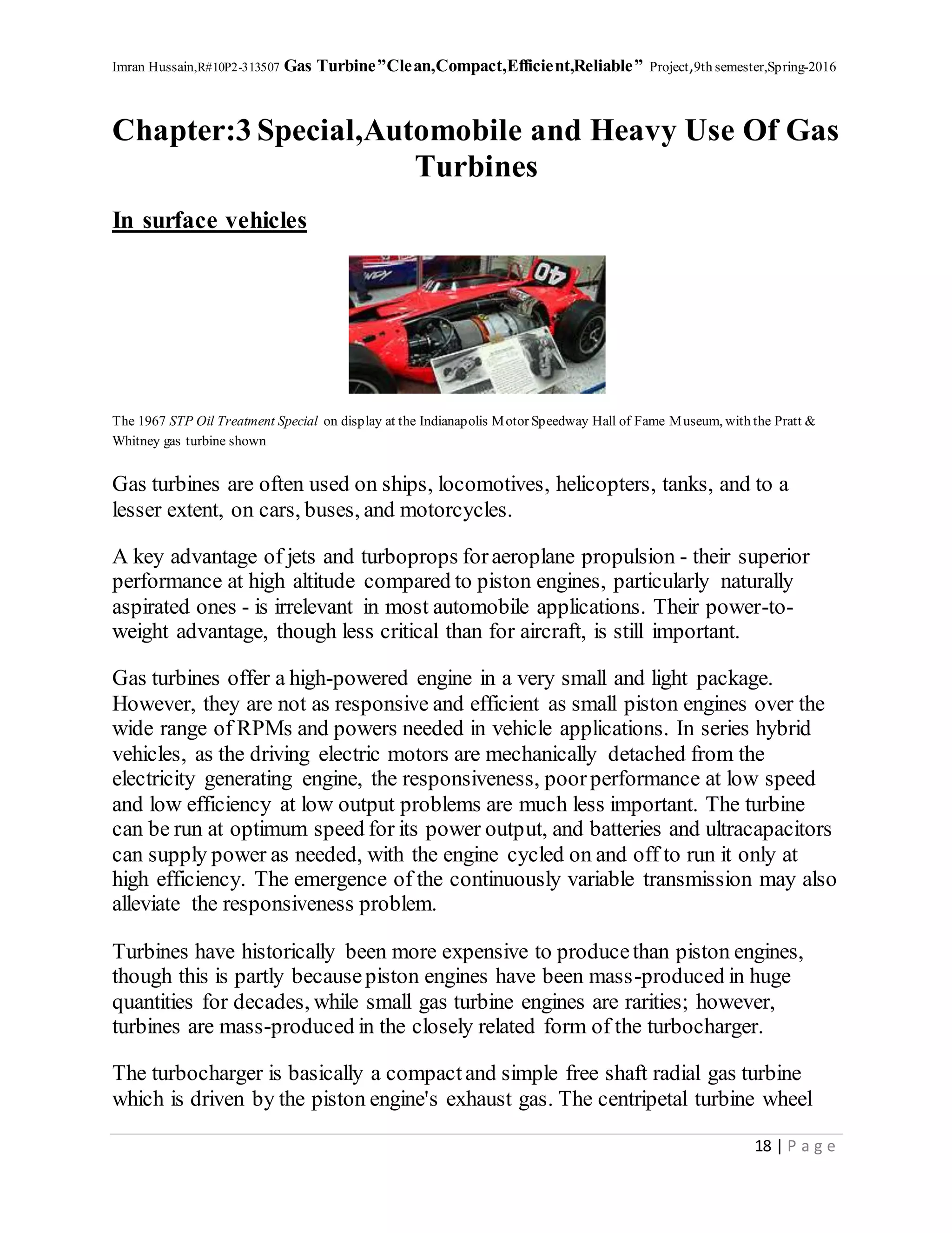
Microturbines are becoming widespread in distributed power and combined heat
and power applications, and are very promising for powering hybrid electric
vehicles. They range from hand held units producing less than a kilowatt, to
commercial sized systems that producetens or hundreds of kilowatts. Basic
principles of microturbine are based on micro-combustion.
Part of their claimed success is said to be due to advances in electronics, which
allows unattended operation and interfacing with the commercial power grid.
Electronic power switching technology eliminates the need for the generator to be
synchronized with the power grid. This allows the generator to be integrated with
the turbine shaft, and to double as the starter motor.
Microturbine systems have many claimed advantages over reciprocating engine
generators, such as higher power-to-weight ratio, low emissions and few, or just
one, moving part. Advantages are that microturbines may be designed with foil
bearings and air-cooling operating without lubricating oil, coolants or other
hazardous materials. Nevertheless, reciprocating engines overall are still cheaper
when all factors are considered. Microturbines also have a further advantage of
having the majority of the waste heat contained in the relatively high temperature
exhaust making it simpler to capture, whereas the waste heat of reciprocating
engines is split between its exhaust and cooling system.[30]
However, reciprocating engine generators are quicker to respond to changes in
output power requirement and are usually slightly more efficient, although the
efficiency of microturbines is increasing. Microturbines also lose more efficiency
at low power levels than reciprocating engines.
Reciprocating engines typically use simple motor oil (journal) bearings. Full-size
gas turbines often use ball bearings. The 1000 °C temperatures and high speeds of
microturbines make oil lubrication and ball bearings impractical; they require air
bearings or possibly magnetic bearings.
16. Imran Hussain,R#10P2-313507 Gas Turbine”Clean,Compact,Efficient,Reliable” Project,9th semester,Spring-2016
16 | P a g e
When used in extended range electric vehicles the static efficiency drawback is
irrelevant, since the gas turbine can be run at or near maximum power, driving an
alternator to produceelectricity either for the wheel motors, or for the batteries, as
appropriate to speed and battery state. The batteries act as a "buffer" (energy
storage) in delivering the required amount of power to the wheel motors, rendering
throttle responseof the gas turbine completely irrelevant.
There is, moreover, no need for a significant or variable-speed gearbox; turning an
alternator at comparatively high speeds allows for a smaller and lighter alternator
than would otherwise be the case. The superior power-to-weight ratio of the gas
turbine and its fixed speed gearbox, allows for a much lighter prime mover than
those in such hybrids as the ToyotaPrius (which utilised a 1.8 litre petrol engine)
or the Chevrolet Volt (which utilises a 1.4 litre petrol engine). This in turn allows a
heavier weight of batteries to be carried, which allows for a longer electric-only
range. Alternatively, the vehicle can use heavier types of batteries such as lead acid
batteries (which are cheaper to buy) or safer types of batteries such as Lithium-
Iron-Phosphate.
When gas turbines are used in extended-range electric vehicles, like those planned
by Land-Rover/Range-Rover in conjunction with Bladon, or by Jaguar also in
partnership with Bladon, the very poorthrottling response(their high moment of
rotational inertia) does not matter, because the gas turbine, which may be spinning
at 100,000 rpm, is not directly, mechanically connected to the wheels. It was this
poorthrottling responsethat so bedevilled the 1950 Rover gas turbine-powered
prototypemotor car, which did not have the advantage of an intermediate electric
drive train to provide suddenpower spikes when demanded by the driver.
Gas turbines acceptmost commercial fuels, such as petrol, natural gas, propane,
diesel, and kerosene as well as renewable fuels such as E85, biodiesel and biogas.
However, when running on kerosene or diesel, starting sometimes requires the
assistance of a more volatile productsuch as propane gas - although the new kero-
start technology can allow even microturbines fuelled on kerosene to start without
propane.
Microturbine designs usually consistof a single stage radial compressor, asingle
stage radial turbine and a recuperator. Recuperators are difficult to design and
manufacture because they operate under high pressure and temperature
differentials. Exhaust heat can be used for water heating, spaceheating, drying
processes or absorptionchillers, which create cold for air conditioning from heat
energy instead of electric energy.
17. Imran Hussain,R#10P2-313507 Gas Turbine”Clean,Compact,Efficient,Reliable” Project,9th semester,Spring-2016
17 | P a g e
Typical microturbine efficiencies are 25 to 35%. When in a combined heat and
power cogeneration system, efficiencies of greater than 80% are commonly
achieved.
Problems have occurred with heat dissipation and high-speed bearings in these new
microturbines. Moreover, their expected efficiency is a very low 5-6%. According
to ProfessorEpstein, current commercial Li-ion rechargeable batteries deliver
about 120-150 W·h/kg. MIT's millimeter size turbine will deliver 500-700 W·h/kg
in the near term, rising to 1200-1500 W∙h/kg in the longer term.
A similar microturbine built in Belgium has a rotor diameter of 20 mm and is
expected to produceabout 1000 W.
2.9 External combustion
Most gas turbines are internal combustionengines but it is also possible to
manufacture an external combustion gas turbine which is, effectively, a turbine
version of a hot air engine. Thosesystems are usually indicated as EFGT
(Externally Fired Gas Turbine) or IFGT (Indirectly Fired Gas Turbine).
External combustion has been used for the purposeof using pulverized coal or
finely ground biomass (such as sawdust) as a fuel. In the indirect system, a heat
exchanger is used and only clean air with no combustionproducts travels through
the power turbine. The thermal efficiency is lower in the indirect type of external
combustion; however, the turbine blades are not subjected to combustion products
and much lower quality (and therefore cheaper) fuels are able to be used.
When external combustion is used, it is possible to use exhaust air from the turbine
as the primary combustion air. This effectively reduces global heat losses, although
heat losses associated with the combustion exhaust remain inevitable.
Closed-cycle gas turbines based on helium or supercritical carbondioxide also
hold promise for use with future high temperature solar and nuclear power
generation.
18. Imran Hussain,R#10P2-313507 Gas Turbine”Clean,Compact,Efficient,Reliable” Project,9th semester,Spring-2016
18 | P a g e
Chapter:3 Special,Automobile and Heavy Use Of Gas
Turbines
In surface vehicles
The 1967 STP Oil Treatment Special on display at the Indianapolis Motor Speedway Hall of Fame Museum, with the Pratt &
Whitney gas turbine shown
Gas turbines are often used on ships, locomotives, helicopters, tanks, and to a
lesser extent, on cars, buses, and motorcycles.
A key advantage of jets and turboprops foraeroplane propulsion - their superior
performance at high altitude compared to piston engines, particularly naturally
aspirated ones - is irrelevant in most automobile applications. Their power-to-
weight advantage, though less critical than for aircraft, is still important.
Gas turbines offer a high-powered engine in a very small and light package.
However, they are not as responsive and efficient as small piston engines over the
wide range of RPMs and powers needed in vehicle applications. In series hybrid
vehicles, as the driving electric motors are mechanically detached from the
electricity generating engine, the responsiveness, poorperformance at low speed
and low efficiency at low output problems are much less important. The turbine
can be run at optimum speed for its power output, and batteries and ultracapacitors
can supply power as needed, with the engine cycled on and off to run it only at
high efficiency. The emergence of the continuously variable transmission may also
alleviate the responsiveness problem.
Turbines have historically been more expensive to producethan piston engines,
though this is partly becausepiston engines have been mass-produced in huge
quantities for decades, while small gas turbine engines are rarities; however,
turbines are mass-produced in the closely related form of the turbocharger.
The turbocharger is basically a compactand simple free shaft radial gas turbine
which is driven by the piston engine's exhaust gas. The centripetal turbine wheel
19. Imran Hussain,R#10P2-313507 Gas Turbine”Clean,Compact,Efficient,Reliable” Project,9th semester,Spring-2016
19 | P a g e
drives a centrifugal compressor wheel through a common rotating shaft. This
wheel supercharges the engine air intake to a degree that can be controlled by
means of a wastegate or by dynamically modifying the turbine housing's geometry
(as in a VGT turbocharger). It mainly serves as a power recovery device which
converts a great deal of otherwise wasted thermal and kinetic energy into engine
boost.
Turbo-compound engines (actually employed on some trucks) are fitted with blow
down turbines which are similar in design and appearance to a turbocharger except
for the turbine shaft being mechanically or hydraulically connected to the engine's
crankshaft instead of to a centrifugal compressor, thus providing additional power
instead of boost. While the turbocharger is a pressureturbine, a power recovery
turbine is a velocity one.
3.1 Passengerroadvehicles (cars, bikes, and buses)
A number of experiments have been conducted with gas turbine powered
automobiles, the largest by Chrysler. More recently, there has been some interest in
the use of turbine engines for hybrid electric cars. For instance, a consortium led
by micro gas turbine company Bladon Jets has secured investment from the
Technology Strategy Board to develop an Ultra Lightweight Range Extender
(ULRE) for next generation electric vehicles. The objective of the consortium,
which includes luxury car maker Jaguar Land Rover and leading electrical machine
company SR Drives, is to producethe world’s first commercially viable - and
environmentally friendly - gas turbine generator designed specifically for
automotive applications. The common turbocharger for gasoline or diesel engines
is also a turbine derivative.
3.1.1 Conceptcars
The first serious investigation of using a gas turbine in cars was in 1946 when two
engineers, RobertKafka and Robert Engerstein of Carney Associates, a New York
engineering firm, came up with the conceptwhere a unique compactturbine engine
design would provide power for a rear wheel drive car.
20. Imran Hussain,R#10P2-313507 Gas Turbine”Clean,Compact,Efficient,Reliable” Project,9th semester,Spring-2016
20 | P a g e
The 1950 Rover JET1
In 1950, designer F.R. Bell and Chief Engineer Maurice Wilks from British car
manufacturers Rover unveiled the first car powered with a gas turbine engine. The
two-seater JET1 had the engine positioned behind the seats, air intake grilles on
either side of the car, and exhaust outlets on the top of the tail. During tests, the car
reached top speeds of 140 km/h (87 mph), at a turbine speed of 50,000 rpm. The
car ran on petrol, paraffin (kerosene) or diesel oil, but fuel consumption problems
proved insurmountable for a productioncar. It is on display at the London Science
Museum.
Starting in 1954 with a modified Plymouth, the American car manufacturer
Chrysler demonstrated several prototypegas turbine-powered cars from the early
1950s through the early 1980s. Chrysler built fifty Chrysler Turbine Cars in 1963
and conducted the only consumer trial of gas turbine-powered cars. Each of their
turbines employed a unique rotating recuperator, referred to as a regenerator that
increased efficiency.
Engine compartment of a Chrysler 1963 Turbine car
In 1954 FIAT unveiled a conceptcar with a turbine engine, called Fiat Turbina.
This vehicle, looking like an aircraft with wheels, used a unique combination of
both jet thrust and the engine driving the wheels. Speeds of 282 km/h (175 mph)
were claimed.
21. Imran Hussain,R#10P2-313507 Gas Turbine”Clean,Compact,Efficient,Reliable” Project,9th semester,Spring-2016
21 | P a g e
The original General Motors Firebird was a series of conceptcars developed for
the 1953, 1956 and 1959 Motorama auto shows, powered by gas turbines.
At the 2010 Paris Motor Show Jaguar demonstrated its Jaguar C-X75 conceptcar.
This electrically powered supercar has a top speed of 204 mph (328 km/h) and can
go from 0 to 62 mph (0 to 100 km/h) in 3.4 seconds. It uses Lithium-ion batteries
to power 4 electric motors which combine to producesome 780 bhp. It will do 68
miles (109 km) on a single charge of the batteries, but in addition it uses a pair of
Bladon Micro Gas Turbines to re-charge the batteries extending the range to 560
miles (900 km).
3.1.2 Racing cars
The first race car (in conceptonly) fitted with a turbine was in 1955 by a US Air
Forcegroup as a hobbyproject with a turbine loaned them by Boeing and a race
car owned by Firestone Tire & Rubber company. The first race car fitted with a
turbine for the goal of actual racing was by Rover and the BRM Formula One team
joined forces to producethe Rover-BRM, a gas turbine powered coupe, which
entered the 1963 24 Hours of Le Mans, driven by Graham Hill and Richie Ginther.
It averaged 107.8 mph (173.5 km/h) and had a top speed of 142 mph (229 km/h).
For open wheel racing, 1967's revolutionary STP-PaxtonTurbocar fielded by
racing and entrepreneurial legend Andy Granatelli and driven by Parnelli Jones
nearly won the Indianapolis 500; the Pratt & Whitney ST6B-62 powered turbine
car was almost a lap ahead of the second place car when a gearbox bearing failed
just three laps from the finish line. The next year the STP Lotus 56 turbine car won
the Indianapolis 500 pole position even though new rules restricted the air intake
dramatically. In 1971 Lotus principal Colin Chapman introduced the Lotus 56B F1
car, powered by a Pratt & Whitney STN6/76 gas turbine. Chapman had a
reputation of building radical championship-winning cars, but had to abandon the
project becausethere were too many problems with turbo lag.
3.1.3 Buses
The arrival of the CapstoneMicroturbine has led to several hybrid bus designs,
starting with HEV-1 by AVS of Chattanooga, Tennessee in 1999, and closely
followed by Ebus and ISE Research in California, and DesignLine Corporationin
New Zealand (and later the United States). AVS turbine hybrids were plagued with
reliability and quality control problems, resulting in liquidation of AVS in 2003.
The most successfuldesign by Designline is now operated in 5 cities in 6
22. Imran Hussain,R#10P2-313507 Gas Turbine”Clean,Compact,Efficient,Reliable” Project,9th semester,Spring-2016
22 | P a g e
countries, with over 30 buses in operation worldwide, and order for several
hundred being delivered to Baltimore, and NYC.
Brescia Italy is using serial hybrid buses powered by microturbines on routes
through the historical sections of the city.
3.1.4 Motorcycles
The MTT Turbine Superbike appeared in 2000 (hence the designation of Y2K
Superbike by MTT) and is the first production motorcycle powered by a turbine
engine - specifically, a Rolls-Royce Allison model 250 turboshaft engine,
producing about 283 kW (380 bhp). Speed-tested to 365 km/h or 227 mph
(according to some stories, the testing team ran out of road during the test), it holds
the Guinness World Record for most powerful production motorcycle and most
expensive production motorcycle, with a price tag of US$185,000.
3.1.5Trains
Several locomotive classes have been powered by gas turbines, the most recent
incarnation being Bombardier's JetTrain.
3.2 Military Tanks
Marines from1st TankBattalionloada Honeywell AGT1500 multi-fuel turbine back intoan M1Abrams tank at CampCoyote, Kuwait,
February 2003
The German Army's development division, the Heereswaffenamt (Army Ordnance
Board), studied a number of gas turbine engines for use in tanks starting in mid-
1944. The first gas turbine engines used for armoured fighting vehicle GT 101 was
installed in the Panther tank. The second use of a gas turbine in an armoured
fighting vehicle was in 1954 when a unit, PU2979, specifically developed for tanks
by C. A. Parsons & Co., was installed and trialled in a British Conqueror tank.[53]
The Stridsvagn 103 was developed in the 1950s and was the first mass-produced
main battle tank to use a turbine engine. Since then, gas turbine engines have been
23. Imran Hussain,R#10P2-313507 Gas Turbine”Clean,Compact,Efficient,Reliable” Project,9th semester,Spring-2016
23 | P a g e
used as APUs in some tanks and as main powerplants in Soviet/Russian T-80s and
U.S. M1 Abrams tanks, among others. They are lighter and smaller than diesels at
the same sustained power output but the models installed to date are less fuel
efficient than the equivalent diesel, especially at idle, requiring more fuel to
achieve the same combat range. Successivemodels of M1 have addressed this
problem with battery packs or secondarygenerators to power the tank's systems
while stationary, saving fuel by reducing the need to idle the main turbine. T-80s
can mount three large external fuel drums to extend their range. Russia has stopped
production of the T-80 in favour of the diesel-powered T-90 (based on the T-72),
while Ukraine has developed the diesel-powered T-80UD and T-84 with nearly the
power of the gas-turbine tank. The French Leclerc MBT's diesel powerplant
features the "Hyperbar" hybrid supercharging system, where the engine's
turbocharger is completely replaced with a small gas turbine which also works as
an assisted diesel exhaust turbocharger, enabling engine RPM-independent boost
level control and a higher peak boostpressureto be reached (than with ordinary
turbochargers). This system allows a smaller displacement and lighter engine to be
used as the tank's powerplant and effectively removes turbo lag. This special gas
turbine/turbocharger can also work independently from the main engine as an
ordinary APU.
Like most modern diesel engines used in tanks, gas turbines are usually multi-fuel
engines.
3.3 Marine applications
3.3.1 Naval
The Gas turbine from MGB 2009
Gas turbines are used in many naval vessels, where they are valued for their high
power-to-weight ratio and their ships' resulting acceleration and ability to get
underway quickly.
24. Imran Hussain,R#10P2-313507 Gas Turbine”Clean,Compact,Efficient,Reliable” Project,9th semester,Spring-2016
24 | P a g e
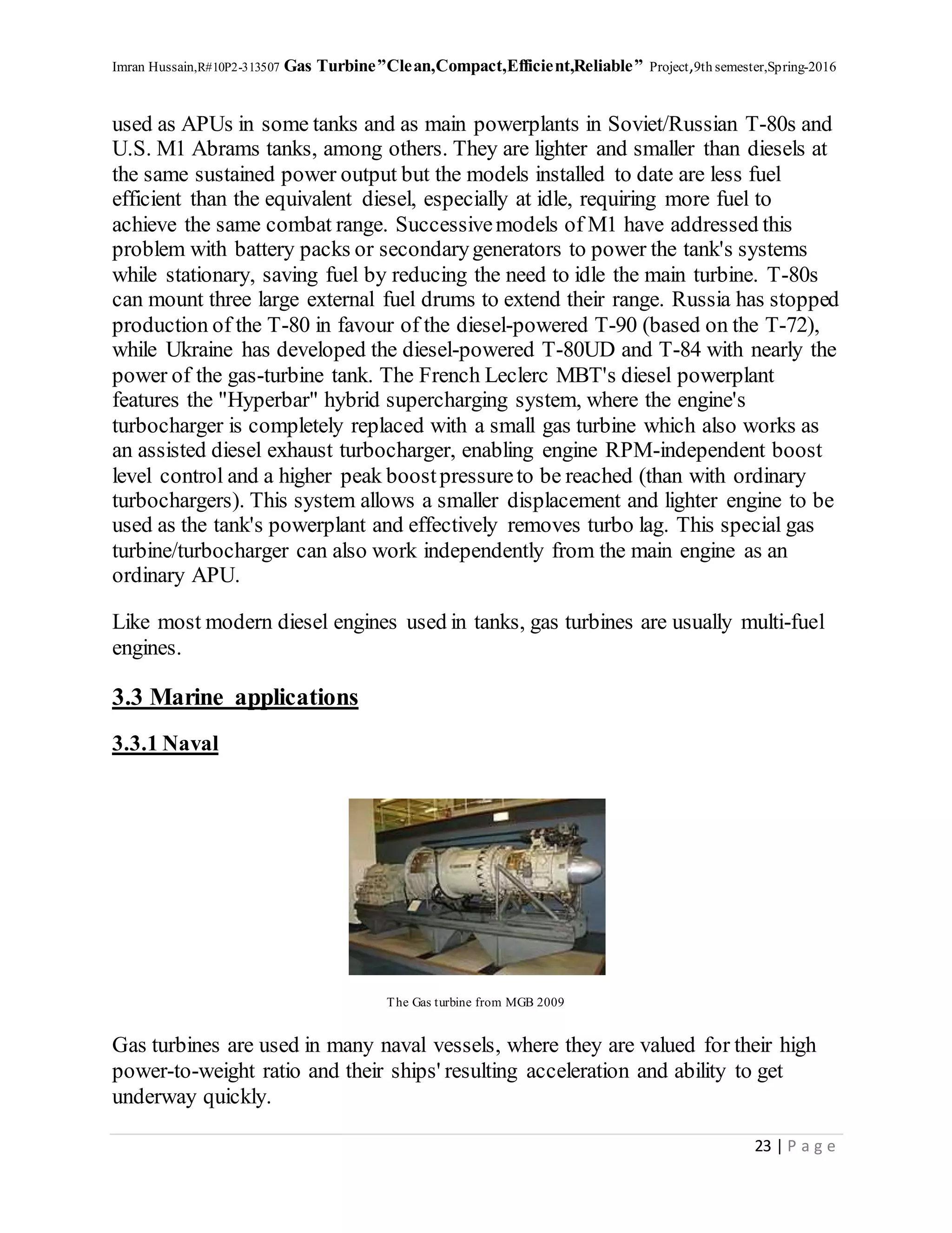
The first gas-turbine-powered naval vessel was the Royal Navy's Motor Gun Boat
MGB 2009 (formerly MGB 509)converted in 1947. Metropolitan-Vickers fitted
their F2/3 jet engine with a power turbine. The Steam Gun Boat Grey Goose was
converted to Rolls-Royce gas turbines in 1952 and operated as such from 1953.
The Bold class FastPatrol Boats Bold Pioneer and Bold Pathfinder built in 1953
were the first ships created specifically for gas turbine propulsion.
The first large scale, partially gas-turbine powered ships were the Royal Navy's
Type 81 (Tribal class) frigates with combined steam and gas powerplants. The
first, HMS Ashantiwas commissioned in 1961.
The German Navy launched the first Köln-class frigate in 1961 with 2 Brown,
Boveri & Cie gas turbines in the world's first combined diesel and gas propulsion
system.
The Danish Navy had 6 Søløven-class torpedo boats (the export version of the
British Brave class fast patrol boat) in service from 1965 to 1990, which had 3
Bristol Proteus (later RR Proteus) Marine Gas Turbines rated at 9,510 kW
(12,750 shp) combined, plus two General Motors Diesel engines, rated at 340 kW
(460 shp), for better fuel economy at slower speeds.[56] And they also produced 10
Willemoes Class Torpedo / Guided Missile boats (in service from 1974 to 2000)
which had 3 Rolls RoyceMarine Proteus Gas Turbines also rated at 9,510 kW
(12,750 shp), same as the Søløven-class boats, and 2 General Motors Diesel
Engines, rated at 600 kW (800 shp), also for improved fuel economy at slow
speeds.
The next series of major naval vessels were the four Canadian Iroquois-class
helicopter carrying destroyers first commissioned in 1972. They used 2 ft-4 main
propulsion engines, 2 ft-12 cruise engines and 3 Solar Saturn 750 kW generators.
An LM2500 gas turbine on USS Ford
25. Imran Hussain,R#10P2-313507 Gas Turbine”Clean,Compact,Efficient,Reliable” Project,9th semester,Spring-2016
25 | P a g e
The first U.S. gas-turbine powered ship was the U.S. Coast Guard's Point
Thatcher, a cutter commissioned in 1961 that was powered by two 750 kW
(1,000 shp) turbines utilizing controllable-pitch propellers. The larger Hamilton-
class High Endurance Cutters, was the first class of larger cutters to utilize gas
turbines, the first of which (USCGC Hamilton) was commissioned in 1967. Since
then, they have powered the U.S. Navy's Oliver Hazard Perry-class frigates,
Spruanceand Arleigh Burke-class destroyers, and Ticonderoga-class guided
missile cruisers. USS Makin Island, a modified Wasp-class amphibious assault
ship, is to be the Navy's first amphibious assault ship powered by gas turbines. The
marine gas turbine operates in a more corrosive atmosphere due to presence of sea
salt in air and fuel and use of cheaper fuels.
3.3.2 Civilian maritime
Up to the late 1940s much of the progress on marine gas turbines all over the world
took place in design offices and engine builder's workshops and development work
was led by the British Royal Navy and other Navies. While interest in the gas
turbine for marine purposes, bothnaval and mercantile, continued to increase, the
lack of availability of the results of operating experience on early gas turbine
projects limited the number of new ventures on seagoing commercial vessels being
embarked upon. In 1951, the Diesel-electric oil tanker Auris, 12,290 Deadweight
tonnage (DWT) was used to obtain operating experience with a main propulsion
gas turbine under service conditions at sea and so became the first ocean-going
merchant ship to be powered by a gas turbine. The Auris operated commercially as
a tanker for three-and-a-half years with a diesel-electric propulsion unit as
originally commissioned, but in 1951 one of its four 824 kW (1,105 bhp) diesel
engines – which were known as "Faith", "Hope", "Charity" and "Prudence" - was
replaced by the world’s first marine gas turbine engine, a 890 kW (1,200 bhp)
open-cycle gas turbo-alternator built by British Thomson-HoustonCompany in
Rugby. The Auris then had all of its power plants replaced with a 3,910 kW
(5,250 shp) directly coupled gas turbine to becomethe first civilian ship to operate
solely on gas turbine power.
The United States Maritime Commission were looking for options to update WWII
Liberty ships, and heavy-duty gas turbines were one of those selected. In 1956 the
John Sergeant was lengthened and equipped with a General Electric 4,900 kW
(6,600 shp) HD gas turbine with exhaust-gas regeneration, reduction gearing and a
variable-pitch propeller.
26. Imran Hussain,R#10P2-313507 Gas Turbine”Clean,Compact,Efficient,Reliable” Project,9th semester,Spring-2016
26 | P a g e
Boeing launched its first passenger-carrying waterjet-propelled hydrofoil Boeing
929, in April 1974. Those ships were powered by twin Allison gas turbines of the
KF-501 series.
Boeing Jetfoil 929-100-007 Urzela of TurboJET
The first passenger ferry to use a gas turbine was the GTS Finnjet, built in 1977
and powered by two Pratt & Whitney FT 4C-1 DLF turbines, generating
55,000 kW (74,000 shp) and propelling the ship to a speed of 31 knots. However,
the Finnjet also illustrated the shortcomings of gas turbine propulsion in
commercial craft, as high fuel prices made operating her unprofitable. After four
years of service additional diesel engines were installed on the ship to reduce
running costs during the off-season. The Finnjet was also the first ship with a
Combined diesel-electric and gas propulsion.
In July 2000 the Millennium became the first cruise ship to be propelled by gas
turbines, in a Combined Gas and Steam Turbine configuration. The liner RMS
Queen Mary 2 uses a Combined Diesel and Gas Turbine configuration.[63]
In marine racing applications the 2010 C5000 Mystic catamaran Miss GEICO uses
two Lycoming T-55 turbines for its power system.
27. Imran Hussain,R#10P2-313507 Gas Turbine”Clean,Compact,Efficient,Reliable” Project,9th semester,Spring-2016
27 | P a g e
Chapter:4 Gas Turbine Power Plants
A gas turbine power plant consists of a rotary multistage compressor, generally of
axial flow type, in which air or working substance is compressed. Compressed air
flows to the combustion chamber where fuel is burnt, thereby raising the
temperature of the working substance. The high pressure, high temperature
working substanceexpands in a turbine producing mechanical power. Turbine in
turn drives a generator for producing electrical energy. A gas turbine works
on Brayton cycle.
4.1 Simple Gas Turbine power plant Cycle
Simple Gas Turbine Cycle
The compressor,combustorand turbine are connected by one or more shafts and
are collectively called the gas generator or gas turbine. Figures below illustrate the
typical gas turbine generator configuration and schematic.
Open Cycle Gas Turbine Configuration
28. Imran Hussain,R#10P2-313507 Gas Turbine”Clean,Compact,Efficient,Reliable” Project,9th semester,Spring-2016
28 | P a g e
Open Cycle Gas Turbine Schematic
4.2 Combined cycle power Plant:
Combined-cycle power system typically uses a gas turbine to drive an electrical
generator, and recovers waste heat from the turbine exhaust to generate steam. The
steam from waste heat is run through a steam turbine to provide supplemental
electricity. The overall electrical efficiency of a combined-cycle power system is
typically in the range of 50–60% — a substantial improvement over the efficiency
of a simple, open-cycle application of around 33%.
A combined-cycle power system is the traditional technology of choice for most
large onshore power generation plants, and is therefore well established. The
technology have also been used on a few offshore installations for over 10 years.
Most offshore installations are designed to generate power from open-cycle gas
turbines which offer reduced capital costs, size and weight (per MW installed), but
with compromised energy efficiency and fuel costs per unit output. Combined-
cycle system operation is suitable for stable load applications, but less suitable for
offshore applications with variable or declining load profiles. In a new ‘greenfield’
development incorporating a combined-cycle system design, the size of the gas
turbine can be optimized and is likely to be smaller than an equivalent open-cycle
configuration. Additionally, the waste heat recovery unit (WHRU) can replace the
gas turbine silencer, thereby mitigating some of the space and weight
constraints. Residual heat may be used instead of fired heaters, thereby improving
the overall system efficiency. As such, the use of combined-cycle power
29. Imran Hussain,R#10P2-313507 Gas Turbine”Clean,Compact,Efficient,Reliable” Project,9th semester,Spring-2016
29 | P a g e
technology is dependent on the power and heat demand of the installation.
Combined-cycle technology is most cost-effective for larger plants. On an
installation where the heat demand is large, the waste heat from the WHRU will
normally be used for other heating applications, and hence there will be little
residual heat left for power generation.
Retrofitting gas turbine generator technology to convert from simple, open-cycle
systems to combined-cycle operation is complex and costly; hence this is not
common in offshore installations. The additional topsideweight and space
necessary to incorporate a steam turbine, as well as the need for additional
personnel on the platform to manage the steam system operations, makes a
combined-cycle retrofit a challenging project.
A combined-cycle power system typically consists of the following equipment: gas
turbines (GTs);waste heat recovery units for steam generation (WHRU-SG);
steam turbines (STs);condensers;and other auxiliary equipment. The figure below
illustrates a combined-cycle power system using a gas turbine generator with waste
heat recovery and steam turbine generator.
Combinedcycle power system using a gas turbine generatorwith waste heat recovery and steam turbine generator
The efficiency of simple Brayton cycle can be improved by
(i) Use of heat exchanger between compressordelivery and combustionchamber,
utilizing heat of exhaust gases;
(ii) Use of two stage expansion with re-heating;
30. Imran Hussain,R#10P2-313507 Gas Turbine”Clean,Compact,Efficient,Reliable” Project,9th semester,Spring-2016
30 | P a g e
(iii) Use of multistage compressionwith inter-cooling.
A gas turbine using atmospheric air as working medium is known as open cycle
gas turbine. In closed cycle gas turbine the working substanceis recirculated and it
does not come into direct contact with atmospheric air. A fluid with better
thermodynamic properties can be used as working substancein such turbines.
Gas turbines can run on gaseous, liquid as well as solid fuels. As compared to a
steam turbine, it does not require condenser and associated bulky cooling
arrangements. Gas turbines operate on lower pressures as compared to steam
turbines hence stress on various parts is less.
For starting a gas turbine enough power is required to drive the compressorwhich
is nearly 30 to 40% of the normal output.
Sometimes gas turbines are used in combination with steam cycle where exhaust
heat of the gas turbine is used in boiler for steam cycle.
Gas Turbine cycle modified for higher efficiency
4.3 Main System Of Gaas Turbine Power Plant
These are the main Aiuxiliary systems in a Gas Turbine Power Plant. Many other
systems and subsystems also form part of the complex system required for the
operation of the Gas Turbine Power Plant.
4.3.1 Air Intake System
Air Intake System provides clean air into the compressor. During continuous
operation the impurities and dust in the air deposits on the compressorblades. This
31. Imran Hussain,R#10P2-313507 Gas Turbine”Clean,Compact,Efficient,Reliable” Project,9th semester,Spring-2016
31 | P a g e
reduces the efficiency and output of the plant . The Air Filter in the Air Intake
system prevents this.
A blade cleaning system comprising of a high pressure pump provides on line
cleaning facility for the compressorblades.Theflow of the large amount of air into
the compressorcreates high noise levels. A Silencer in the intake ductreduces the
noise to acceptable levels.
4.3.2 ExhaustSystem
Exhaust system discharges the hot gases to a level which is safe for the people and
the environment. The exhaust gas that leaves the turbine is around 550 °C. This
includes an outlet stack high enough for the safe discharge of the gases.
Silencer in the outlet stack reduces the noise to acceptable levels.
In Combined Cycle power plants the exhaust system has a ‘diverter damper’ to
change the flow of gases to the Heat Recovery Boilers instead of the outlet stack.
4.3.3 Starting System
Starting system provides the initial momentum for the Gas Turbine to reach the
operating speed. This is similar to the starter motor of your car. The gas turbine in
a power plant runs at 3000 RPM (for the 50 Hz grid - 3600 RPM for the 60 Hz
grid). During starting the speed has to reach at least 60 % for the turbine to work
on its on inertia. The simple method is to have a starter motor with a torque
converter to bring the heavy mass of the turbine to the required speed. For large
turbines this means a big capacity motor. The latest trend is to use the generator
itself as the starter motor with suitable electrics. In situations where there is no
other start up power available, like a ship or an off-shore platform or a remote
location, a small diesel or gas engine is used.
4.3.4 FuelSystem
The Fuel system prepares a clean fuel for burning in the combustor. Gas
Turbines normally burn Natural gas but can also fire diesel or distillate fuels.
Many Gas Turbines have dual firing capabilities.
A burner system and ignition system with the necessary safety interlocks are the
most important items. A control valve regulates the amount of fuel burned . A filter
prevents entry of any particles that may clog the burners. Natural gas directly from
the wells is scrubbed and cleaned prior to admission into the turbine. External
heaters heat the gas for better combustion.
32. Imran Hussain,R#10P2-313507 Gas Turbine”Clean,Compact,Efficient,Reliable” Project,9th semester,Spring-2016
32 | P a g e
For liquid fuels high pressure pumps pump fuel to the pressure required for fine
atomisation of the fuel for burning.
Gas power plants can be powered by several different types of fuels, but natural
gas is the most suitable. This is becauseit is the least expensive and causes the
least pollution. If natural gas is too expensive or not readily available, gas power
plants can operate using most liquid fuels. Forexample, No. 2 fuel oil, also known
as heating oil, is a common substitute for natural gas. No. 2 fuel oil is a petroleum
derivative very similar to diesel fuel. It is used to fuel furnaces, boilers, and gas
turbines. Biogas, which is created when organic matter decomposesin the absence
of oxygen, is also used to fuel gas turbine power plants. Biogas can be generated at
landfill sites and sewage plants, or by decaying agricultural waste. The gas is
collected and used in the combustion chamber in place of natural gas.
4.4 Balance ofplant (BOP) is a term generally used in the context of power
engineering to refer to all the supporting components and auxiliary systems of a
power plant needed to deliver the energy, other than the generating unit itself.
These may include transformers, inverters, supporting structures etc., depending on
the type of plant.
33. Imran Hussain,R#10P2-313507 Gas Turbine”Clean,Compact,Efficient,Reliable” Project,9th semester,Spring-2016
33 | P a g e
Typical BOP systems include but are not limited to
Liquid Fuel Treatment/Forwarding/Storage
Gas Fuel Compression
De-mineralized Water Treatment
Plant Instrument Air
Plant Cooling Water Systems
Switchgear Interface
Emergency Diesel Generator
Black Start Diesel Generator
Cooling Towers
4.5 Weather Conditions for GT Power plants
The power production of a gas turbine is greatly affected by weather conditions.
Generally, the colder the inlet temperatures, the more power can be produced. It is
for this reason that many gas turbine manufacturers install air cooling systems
before the compressor. Hotweather, which prevents the coolers from lowering the
air temperature sufficiently for the given application reduces the power output of
the gas turbine. Because cold air is denser than hot air, the colder the air, the higher
the mass flow rate of air is through the turbine, producing more power.
When the weather is warmer, less steam is produced by a plant that is using its
exhaust heat to producesteam to drive a steam turbine. At first glance it might
seem that less steam is produced becauseof the lower exhaust temperatures, but
it is actually because there is less hot exhaust gas flowing out the exhaust
because the warmer inlet temperatures of the gases have lower density.
34. Imran Hussain,R#10P2-313507 Gas Turbine”Clean,Compact,Efficient,Reliable” Project,9th semester,Spring-2016
34 | P a g e
Chapter:5 Gas Turbine Power Plants in Pakistan
Pakistan has an installed electricity generation capacity of 22,797 MW in 2013.
The average demand is 17,000 MW and the shortfall is between 4,000 and 5,000
MW. Oil (35.2 per cent), hydel (29.9 per cent), gas (29 per cent), and nuclear, solar
and imported (6 per cent) are the principal sources. In the next 10 years, peak
electricity demand is expected to rise by four to five per cent, which is roughly
1,500 MW. This dismal forecastis due to a lopsided energy mix, diminishing
indigenous fuel reserves, increasing circular debt and transmission hold-ups.
Pakistan has almost exhausted its gas reserves. Imported oil’s price hikes affect the
budget and its constant supply cannot be guaranteed. Pakistan has the potential to
meet these energy challenges through hydroelectric power, but there are political
and environmental issues in building dams. Rationality demands reducing reliance
on oil and going for alternatives. The development of alternatives does not happen
overnight. Pakistan will have to rely on imported fuels for the interim period at a
huge cost. LNG is difficult to import, using coal has environmental issues, using
shale gas also has environmental issues attached with it, and wind power has
transmission network challenges.[2] With total estimated coal reserves of over
186bn tonnes, Pakistan ranks sixth among coal-rich countries. Yet, coal’s potential
has not been exploited adequately
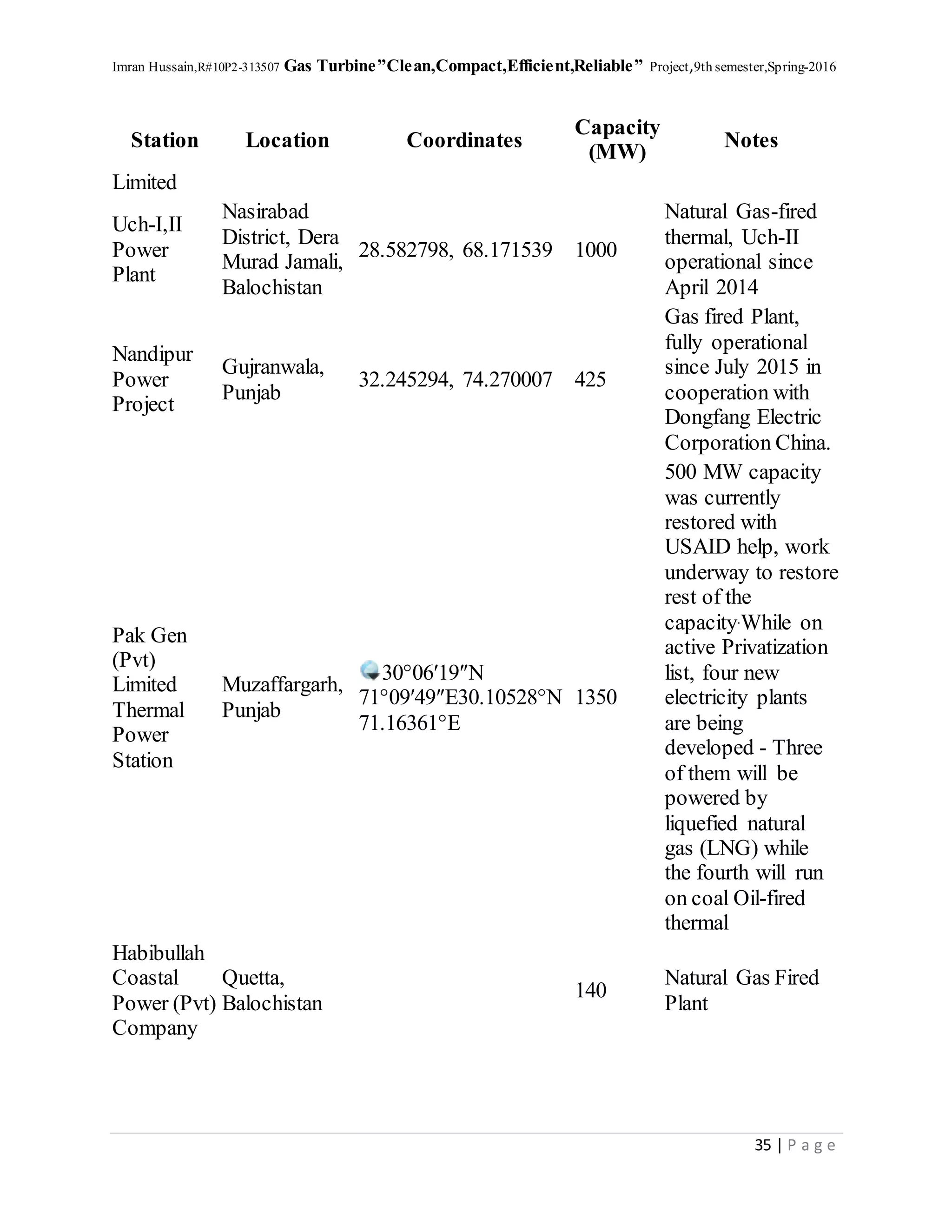
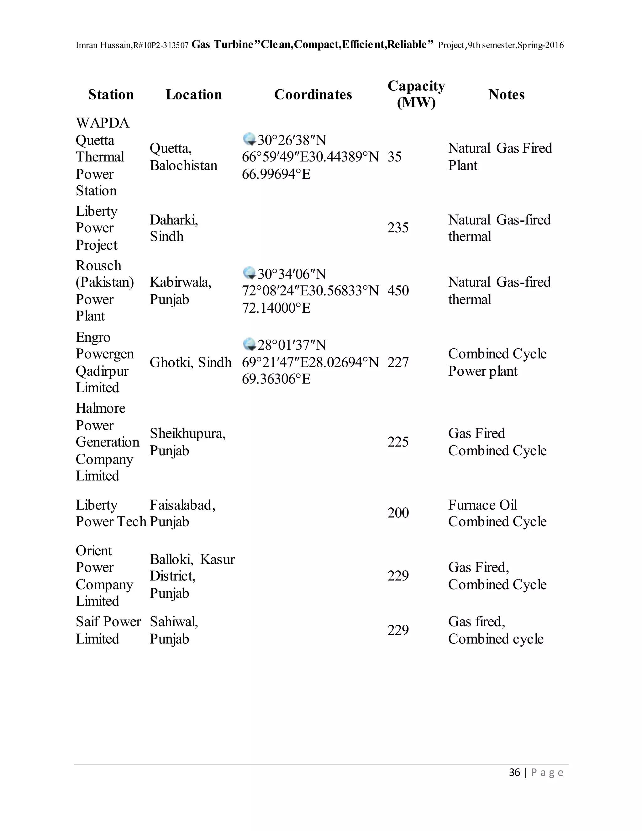
Gas turbine plants List
Station Location Coordinates
Capacity
(MW)
Notes
Kot Addu
Power
Company
Limited
Kot Addu,
Muzaffargarh,
Punjab
30°26′42″N
70°58′52″E30.44500°N
70.98111°E
1,600
Oil and Natural
Gas fired thermal
stations
Guddu
Thermal
Station
Guddu,
Kashmore,
Sindh
28°25′38″N
69°41′49″E28.42722°N
69.69694°E
2,402
Natural Gas-fired
thermal station
Bin Qasim
Power
Plant II
Karachi, Sindh 560
Natural Gas-fired
Combine Cycle
Power station
Foundation
Power
Company
(Daharki)
Daharki,
Sindh
27.985137, 69.673544 185
Combined Cycle
Power Plant
35. Imran Hussain,R#10P2-313507 Gas Turbine”Clean,Compact,Efficient,Reliable” Project,9th semester,Spring-2016
35 | P a g e
Station Location Coordinates
Capacity
(MW)
Notes
Limited
Uch-I,II
Power
Plant
Nasirabad
District, Dera
Murad Jamali,
Balochistan
28.582798, 68.171539 1000
Natural Gas-fired
thermal, Uch-II
operational since
April 2014
Nandipur
Power
Project
Gujranwala,
Punjab
32.245294, 74.270007 425
Gas fired Plant,
fully operational
since July 2015 in
cooperation with
Dongfang Electric
Corporation China.
Pak Gen
(Pvt)
Limited
Thermal
Power
Station
Muzaffargarh,
Punjab
30°06′19″N
71°09′49″E30.10528°N
71.16361°E
1350
500 MW capacity
was currently
restored with
USAID help, work
underway to restore
rest of the
capacity.While on
active Privatization
list, four new
electricity plants
are being
developed - Three
of them will be
powered by
liquefied natural
gas (LNG) while
the fourth will run
on coal Oil-fired
thermal
Habibullah
Coastal
Power (Pvt)
Company
Quetta,
Balochistan
140
Natural Gas Fired
Plant
36. Imran Hussain,R#10P2-313507 Gas Turbine”Clean,Compact,Efficient,Reliable” Project,9th semester,Spring-2016
36 | P a g e
Station Location Coordinates
Capacity
(MW)
Notes
WAPDA
Quetta
Thermal
Power
Station
Quetta,
Balochistan
30°26′38″N
66°59′49″E30.44389°N
66.99694°E
35
Natural Gas Fired
Plant
Liberty
Power
Project
Daharki,
Sindh
235
Natural Gas-fired
thermal
Rousch
(Pakistan)
Power
Plant
Kabirwala,
Punjab
30°34′06″N
72°08′24″E30.56833°N
72.14000°E
450
Natural Gas-fired
thermal
Engro
Powergen
Qadirpur
Limited
Ghotki, Sindh
28°01′37″N
69°21′47″E28.02694°N
69.36306°E
227
Combined Cycle
Power plant
Halmore
Power
Generation
Company
Limited
Sheikhupura,
Punjab
225
Gas Fired
Combined Cycle
Liberty
Power Tech
Faisalabad,
Punjab
200
Furnace Oil
Combined Cycle
Orient
Power
Company
Limited
Balloki, Kasur
District,
Punjab
229
Gas Fired,
Combined Cycle
Saif Power
Limited
Sahiwal,
Punjab
229
Gas fired,
Combined cycle