The document discusses the significance of using system curves for pump selection and operation, presented by Simon Smith, a veteran in the pump industry. It emphasizes how understanding pump curve shapes, operating conditions, and system controls can greatly impact pump performance and efficiency. Additionally, it highlights the range of pumps offered by Ruhrpumpen and their applications across various industries.

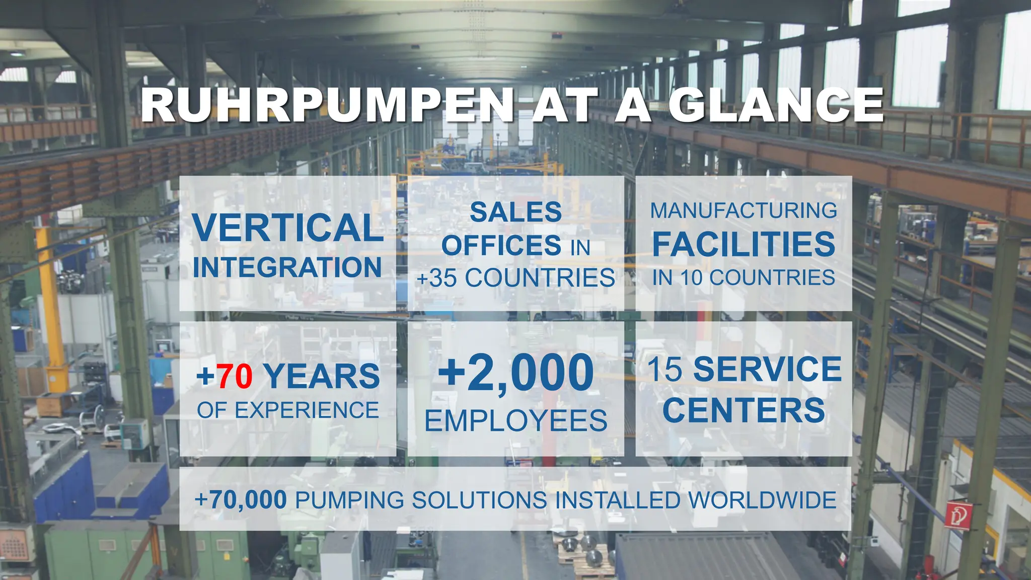
![A GLOBAL COMPANY
MANUFACTURING FACILITIES
USA [Tulsa]
Germany [Witten]
Mexico [Monterrey]
Brazil [Rio de Janeiro]
Argentina [Buenos Aires]
Egypt [Suez]
India [Chennai]
China [Changzhou]
Russia [Moscow]
United Kingdom [Lancing]
Manufacturing facility
& Service center
Service center](https://image.slidesharecdn.com/shortcourse3-importanceofsystemcurvesonpumpselection-241031030010-6b77377a/75/Short-Course-3-Importance-of-System-Curves-on-Pump-Selection-pdf-4-2048.jpg)