Download to read offline
![Patterns, Variants,
Artifacts, and Pitfalls in Conventional
Radionuclide Bone Imaging and SPECT/CT
Gopinath Gnanasegaran, MD,* Gary Cook, MD, FRCR,†
Kathryn Adamson, MSc,* and
Ignac Fogelman, MD*
Bone scintigraphy is one of the most common investigations performed in nuclear
medicine and is used routinely in the evaluation of patients with cancer for suspected
bone metastases and in various benign musculoskeletal conditions. Innovations in
equipment design and other advances, such as single-photon emission computed
tomography (SPECT), positron emission tomography, positron emission tomography/
computed tomography (CT), and SPECT/CT have been incorporated into the investiga-
tion of various musculoskeletal diseases. Bone scans frequently show high sensitivity
but specificity, which is variable or limited. Some of the limited specificity can be
partially addressed by a thorough knowledge and experience of normal variants and
common patterns to avoid misinterpretation. In this review, we discuss the common
patterns, variants, artifacts, and pitfalls in conventional radionuclide planar, SPECT,
and hybrid bone (SPECT/CT) imaging.
Semin Nucl Med 39:380-395 © 2009 Elsevier Inc. All rights reserved.
Radionuclide bone scintigraphy is used as a routine
screening test for suspected bone metastases in a number
of cancers and for the investigation of many benign muscu-
loskeletal conditions because of its sensitivity, low cost, avail-
ability, and the ability to scan the entire skeleton.1,2
In recent years technetium-99m (99mTc)-labeled diphos-
phonates have become the most widely used radiophar-
maceuticals [particularly 99mTc methylene diphosphonate
(99mTc-MDP)].1,2 Bone scans have high sensitivity, but spec-
ificity is frequently variable or limited. Therefore, to increase
the specificity of bone scan interpretation, it is important to
reduce misinterpretation with a comprehensive knowledge
and experience of normal variants and the other patterns,
which may mimic metastases or other musculoskeletal pa-
thology.1-6 A relevant clinical history and other patient infor-
mation may also help avoid misinterpretation. In this review,
we discuss the common patterns, variants, artifacts, and pit-
falls in radionuclide planar, single-photon emission com-
puted tomography (SPECT), and hybrid bone imaging
(SPECT/computed tomography [CT]).
Scintigraphic Techniques
and Instrumentation:
Planar, SPECT, SPECT/CT
Previously, 99mTc-MDP bone scans were acquired as multiple
spot views of the skeleton but modern multiheaded gamma
cameras allow high-resolution, whole-body images of the en-
tire skeleton to be obtained in a short acquisition time. They
also have additional features, such as SPECT, allowing in-
creased sensitivity for lesion detection and 3-dimensional
localization of abnormalities, which aids specificity.1,4-6 Cur-
rently, hybrid technology, such as SPECT/CT provides accu-
rate localization and characterization of equivocal lesions
seen on the bone scan.
SPECT Tracers and
Mechanisms of Uptake
The tracer 99mTc-MDP is the most widely used bone agent,
providing excellent contrast between normal and diseased
*Department of Nuclear Medicine, Guy’s and St Thomas’ Hospital, NHS
Foundation Trust, London, United Kingdom.
†Department of Nuclear Medicine and PET, The Royal Marsden Hospital
NHS Foundation Trust, Surrey, United Kingdom.
Address reprint requests to Gopinath Gnanasegaran, MD, Department of
Nuclear Medicine, St Thomas’ Hospital, Guy’s and St Thomas’ Hospital
NHS Foundation Trust, Lambeth Palace Road, London SE1 7EH, United
Kingdom. E-mail: gopinath.gnanasegaran@gstt.nhs.uk
380 0001-2998/09/$-see front matter © 2009 Elsevier Inc. All rights reserved.
doi:10.1053/j.semnuclmed.2009.07.003](https://image.slidesharecdn.com/gammaosea-variantes2-201105155244/85/Gamma-osea-variantes-2-1-320.jpg)


![37. Wilson MA, Pollack MJ: Gastric visualization and image quality in
radionuclide bone scanning: Concise communication. J Nucl Med
22:518-521, 1981
38. Chaudhuri TK: The effect of aluminum and pH on altered body dis-
tribution of Tc99m EHDP. Int J Nucl Med Biol 3:37, 1976
39. Al-Enizi E, Kazem N, Owunwanne A, et al: Dextrose solutions yield
radiopharmaceutical impurities: The “sweet” scans. J Nucl Med Tech-
nol 31:33-36, 2003
40. Kessler JR, Wells RG, Sty JR: Skeletal scintigraphy: Radiographic arti-
facts. Clin Nucl Med 17:511-512, 1992
41. Dogan A, Rezai K: Incidental lymph node visualisation on bone scan
due to subcutaneous infiltration of Tc99m MDP. Clin Nucl Med 18:
208-209, 1993
42. O’Connor MK, Kelly BJ: Evaluation of techniques for the elimination
of Hot” bladder artifacts in SPECT of the pelvis. J Nucl Med 31:1872-
1875, 1990
43. Bunker SR, Handmaker H, Torre DM, et al: Pixel overflow artifacts in
SPECT evaluation of the skeleton. Radiology 174:229-232, 1990
44. Ogawa K: Image distortion and correction in single photon emission
CT. Ann Nucl Med 18:171-185, 2004
45. O’Connor MK: Instrument- and computer-related problems and arti-
facts in nuclear medicine. Semin Nucl Med 26:256-277, 1996
46. Forstrom LA, Dunn WL, O’Connor MK, et al: Technical pitfalls in
image acquisition, processing, and display. Semin Nucl Med 26:278-
294, 1996
47. Howarth DM, Forstrom LA, O’Connor MK, et al: Patient-related pit-
falls and artifacts in nuclear medicine imaging. Semin Nucl Med 26:
295-307, 1996
48. Kalendar WA: Computed Tomography (ed 2). Erlangen, Germany,
Publicis Corporate Publishing, 2005
49. Popilock R, Sandrasagaren K, Harris L, et al: Artifact recognition for
the nuclear technologist. J Nucl Med Technol 36:79-81, 2008
50. Barrett JF, Keat N: Artefacts in CT: Recognition and avoidance. Radio-
graphics 24:1679-1691, 2004
51. Wilting JE, Timmer J: Artefacts in spiral-CT images and their relation
to pitch and subject morphology. Eur Radiol 9:316-322, 1999
52. Fleischmann D, Rubin GD, Paik DS, et al: Stair-step artifacts with
single versus multiple detector-row helical CT. Radiology 216:185-
196, 2000
53. Silver MD, Taguchi K, Hein IA, et al: Windmill artefact in multislice
CT. Proc SPIE 5032:1918-1927, 2003
54. Zimmer AM, Isitman AT, Holmes RA: Enzymatic inhibition of diphos-
phonate: A proposed mechanism of tissue uptake. J Nucl Med 16:352-
356, 1975
55. Peller P, Ho V, Kransdorf M: Extraosseous Tc99m MDP uptake: A
pathophysiological approach. Radiographics 13:715-734, 1993
56. Duong R, Volarich D, Fernandez-Ulloa M, et al: Tc99m MDP bone
scan artefact: Abdominal soft tissue uptake secondary to subcutane-
ous heparin injection. Clin Nucl Med 9:47, 1984
57. Nizami MA, Gerntholtz T, Swanepoel CR: The role of bone scanning
in the detection of metastatic calcification: A case report. Clin Nucl
Med 25:407-409, 2000
58. Low RD, Hicks RJ, Gill G, et al: Tc99m MDP uptake in a cerebral
infarct. Clin Nucl Med 17:968-970, 1992
59. Padhy AK, Gopinath PG, Amini AC: Myocardial, pulmonary, dia-
phragmatic, gastric, splenic, and renal uptake oft c-99m MDP in pa-
tients with persistent, severe hypercalcemia. Clin Nucleus Med 15:
648-649, 1990
60. Coolens J, Devos P, De Roo M: Diffuse pulmonary uptake of Tc99m
bone imaging agents: Case report and survey. Eur J Nucl Med 11:36-
42, 1985
61. Maloof J, Hurst J, Gupta N: Diffuse pulmonary uptake of Tc99m MDP
in sarcoidosis. Clin Nucl Med 21:77-79, 1996
62. Siegel ME, Walker WJ Jr, Campbell JL: Accumulation of 99mTc-
diphosphonate in malignant pleural effusions. J Nucl Med 16:883-
885, 1975
63. Vanhecke W, Merckx E, De Roo M, et al: Soft tissue uptake on Tc99m
MDP bone scan after cardioversion. Clin Nucl Med 14:923, 1989
64. Lee VW, Caldarone AG, Falk RH, et al: Amyloidosis of heart and liver:
Comparison of Tc99m pyrophosphate and Tc99m methylene diphos-
phonate for detection. Radiology 148:239-242, 1983
65. Atkins HL, Oster ZH: Myocardial uptake of a bone tracer associated
with hypercalcemia. Clin Nucl Med 9:613-615, 1984
66. Ali A, Turner DA, Rosenbush SW, et al: Bone scintigram in cardiac
amyloidosis: A case report. Clin Nucl Med 6:105-108, 1981
67. Piccolo S, Lastoria S, Mainolfi C, et al: Technetium-99m-methylene
diphosphonate scintimammography to image primary breast cancer.
J Nucl Med 36:718-724, 1995
68. Swayne LC: Bone imaging in unusually massive breast carcinoma with
chest wall invasion. Clin Nucl Med 16:593-594, 1991
69. Harvey JA, Fondriest JE, Smith MM: Densely calcified breast mass.
Invest Radiol 29:516-518, 1994
70. Vieras F, Boyd CM: Diagnostic value of renal imaging incidental to
bone scintigraphy with Tc99m phosphate compounds. J Nucl Med
16:1109-1114, 1975
71. Biello DR, Coleman RE, Stanley RJ: Correlation of renal images on
bone scan and intravenous pyelogram. AJR Am J Roentgenol 127:633-
636, 1976
72. Wulfeck DW, Sakow NK, Senler S: Detection of recurrent renal cell
carcinoma by three-phase bone scan. Clin Nucl Med 18:441-443,
1993
73. Bernard M, Hayward M, Hayward C: Evaluation of intense renal pa-
renchymal activity (“Hot Kidneys”) on bone scintigraphy. Clin Nucl
Med 15:254-256, 1990
74. Gentili A, Miron SD, Adler LP, et al: Incidental detection of urinary
tract abnormalities with skeletal scintigraphy. Radiographics 11:571-
579, 1991
75. Straub WH, Slasky BS: Accumulation of bone scanning agent in a
communicating renal cortical cyst. Clin Nucl Med 7:378, 1982
76. Kim SE, Kim DY, Lee DS, et al: Absent or faint renal uptake on bone
scan. Etiology and significance in metastatic bone disease. Clin Nucl
Med 16:545-549, 1991
77. Buxton-Thomas MS, Wraight EP: High renal activity on bone scinti-
grams: A sign of hypercalcaemia? Br J Radiol 56:911-914, 1983
78. Koizumi K, Tonami N, Hisada K: Diffusely increased Tc99m-MDP
uptake in both kidneys. Clin Nucl Med 6:362-365, 1981
79. Lutrin CL, Goris ML: Pyrophosphate retention by previously irradi-
ated renal tissue. Radiology 133:207-209, 1979
80. Trackler RT, Chinn RYW: Amphotericin B therapy: A cause of in-
creased renal uptake of Tc99m MDP. Clin Nuci Med 7:293, 1982
81. Sugimura K, Narabayashi I, Yamazaki K, et al: Bone scintigraphic
findings in 2 cases of myositis ossificans progressiva [Kaku Igaku
Japanese]. J Nucl Med 20:875-879, 1983
82. Chew FS, Hudson TM, Enneking WF: Radionuclide imaging of soft
tissue neoplasms. Semin Nucl Med 11:266-276, 1981
83. Maurer A, Paczolt E, Myers A: Diagnosis of traumatic myositis intrin-
sic muscles of the hand by the use of three-phase skeletal scintigraphy.
Clin Nucl Med 15:535-538, 1990
84. Sud A, Wilson M, Mountz J: Unusual clinical presentation and scin-
tigraphic pattern in myositis ossificans. Clin Nucl Med 17:198-199,
1991
85. Abdel-Dayem H: Tc99m-MDP uptake in rhabdomyolysis. Clin Nucl
Med 6:130, 1981
86. Buchpiguel CA, Roizemblatt S, Pastor EH, et al: Cardiac and skeletal
muscle scintigraphy in dermato- and polymyositis: Clinical implica-
tions. Eur J Nucl Med 23:199-203, 1996
87. Pape HC, Lehmann U, van Griensven M, et al: Heterotopic ossifica-
tions in patients after severe blunt trauma with and without head
trauma: Incidence and patterns of distribution. J Orthop Trauma 15:
229-237, 2001
88. Lafforgue P, Siles S, Daumen-Legre V, et al: An unexpected, benign
cause of increased muscular uptake at bone scintigraphy. Clin Exp
Rheumatol 12:309-311, 1994
89. Romyn AM, Bushnell DL, Freeman ML, et al: Visualization of meta-
static liver disease on technetium-99m bone scintigraphy. Clin Nucl
Med 12:264-267, 1987
394 G. Gnanasegaran et al](https://image.slidesharecdn.com/gammaosea-variantes2-201105155244/85/Gamma-osea-variantes-2-15-320.jpg)


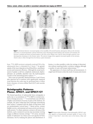
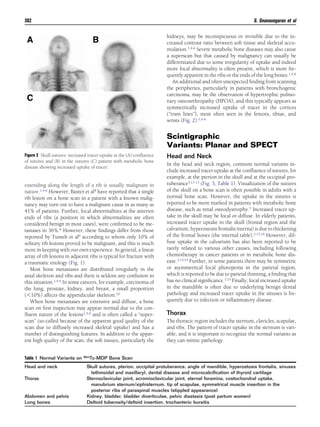
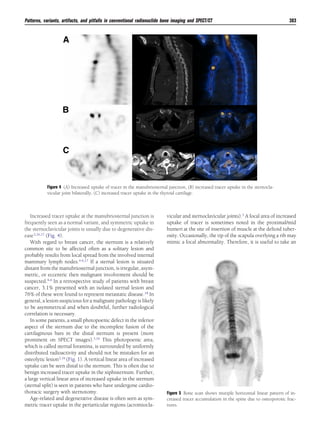
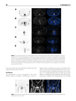
This document discusses patterns, variants, artifacts, and pitfalls seen on conventional radionuclide bone imaging and SPECT/CT scans. It notes that bone scans have high sensitivity but variable specificity. It describes common normal variants seen in the skull, sternum, vertebrae and other bones that can mimic pathology. Knowing these variants is important to avoid misinterpretation of scans. The document also discusses how hybrid SPECT/CT imaging can help characterize indeterminate lesions seen on bone scans.


![[5]Isotope_Scan_Surgical_Diseases](https://cdn.slidesharecdn.com/ss_thumbnails/1664464-thumbnail.jpg?width=640&height=640&fit=bounds)


