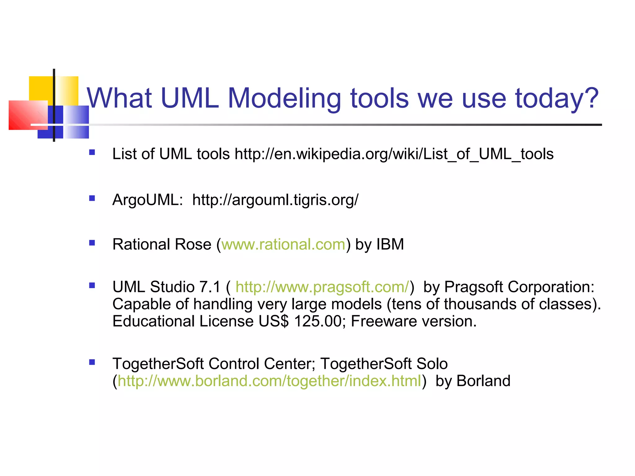
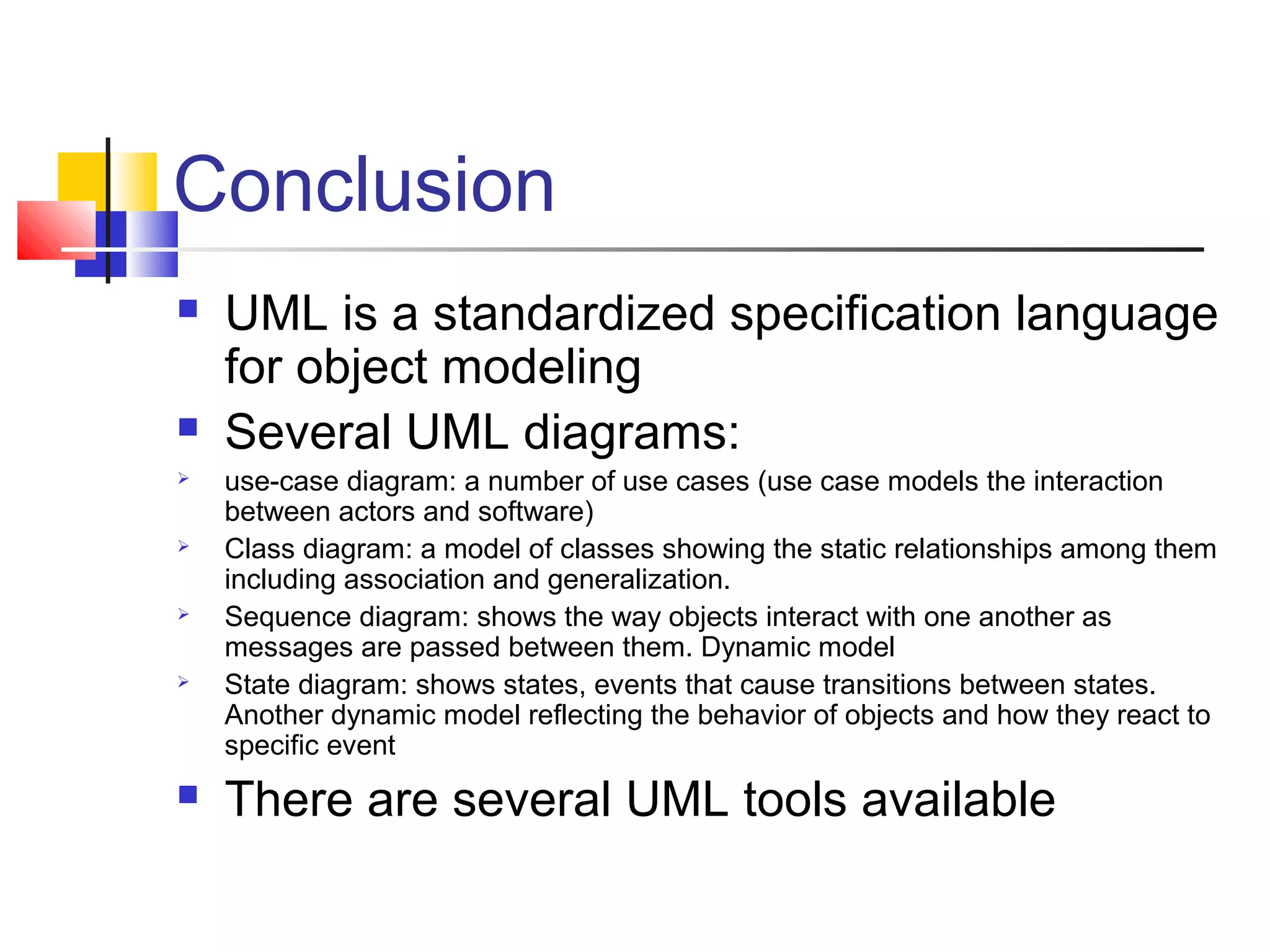
The document discusses UML interaction diagrams, specifically sequence and collaboration diagrams, illustrating how objects interact through message passing. It explains the structure and use of sequence diagrams to show object life spans, activations, and message ordering, while highlighting collaboration diagrams as equivalent but focused on class interactions. Additionally, it mentions various UML modeling tools available for practitioners and concludes with a brief overview of different UML diagram types.
![Sequence Diagram:Object interaction
Self-CallSelf-Call: A message that an
Object sends to itself.
Condition: indicates when a
message is sent. The message is
sent only if the condition is true.
Iteration
Condition
A B
Synchronous
Asynchronous
Transmission
delayed
Self-Call
[condition] remove()
*[for each] remove()](https://image.slidesharecdn.com/session18-190129072832/75/Fundamentals-of-Software-Engineering-3-2048.jpg)
![Sequence Diagram
User Catalog Reservations
1: look up ()
2: title data ()
3: [not available] reserve title ()
4 : title returned ()
5: hold title ()
5 : title available ()
6 : borrow title ()
6 : remove reservation ()
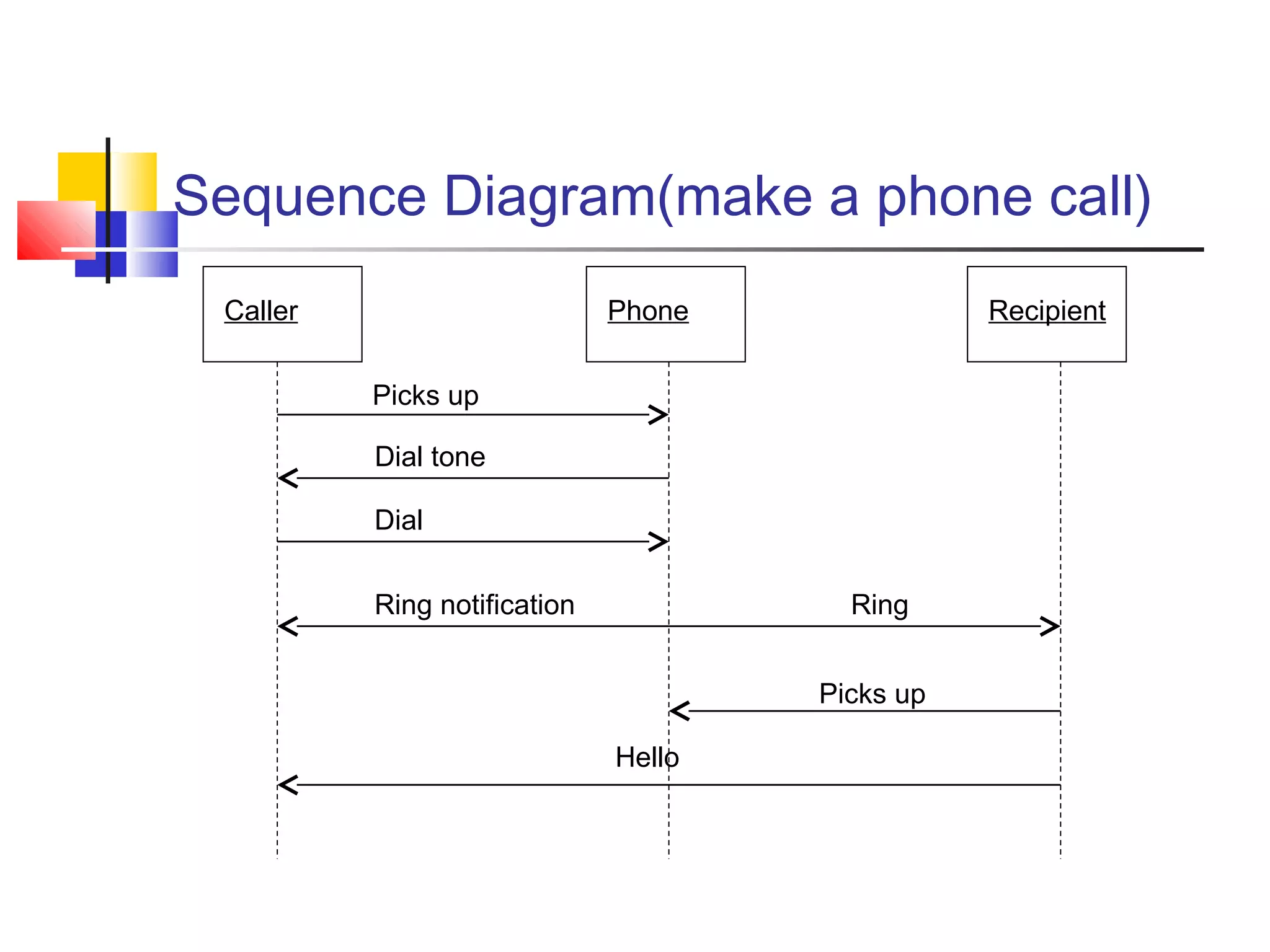
•Sequence diagrams demonstrate the
behavior of objects in a use case by
describing the objects and the
messages they pass.
•The horizontal dimension shows the
objects participating in the interaction.
•The vertical arrangement of
messages indicates their order.
•The labels may contain the seq. # to
indicate concurrency.
Message](https://image.slidesharecdn.com/session18-190129072832/75/Fundamentals-of-Software-Engineering-5-2048.jpg)
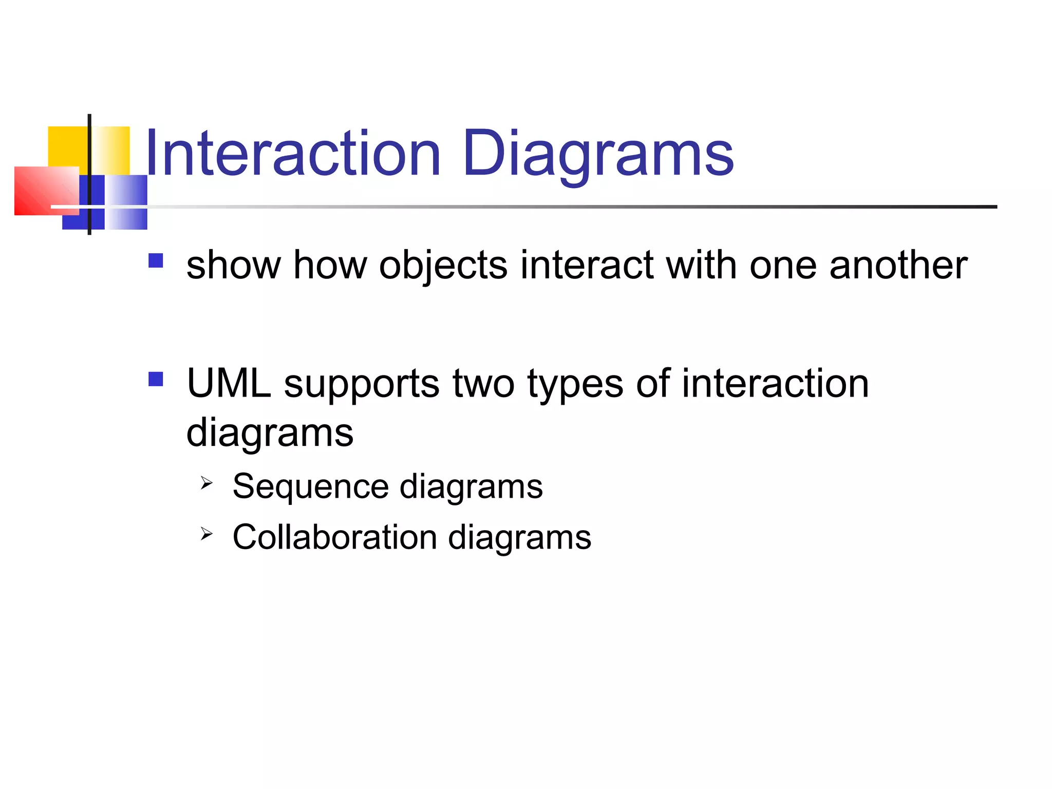
![Interaction Diagrams: Collaboration diagrams
User
Catalog
Reservations
start
1: look up
2: title data
3 : [not available] reserve title
4 : title returned
5 : hold title
6 : borrow title
6: remove reservation
5: title available
Collaboration diagrams are equivalent to sequence diagrams. All the features of sequence diagrams are
equally applicable to collaboration diagrams
Use a sequence diagram when the transfer of information is the focus of attention
Use a collaboration diagram when concentrating on the classes](https://image.slidesharecdn.com/session18-190129072832/75/Fundamentals-of-Software-Engineering-6-2048.jpg)