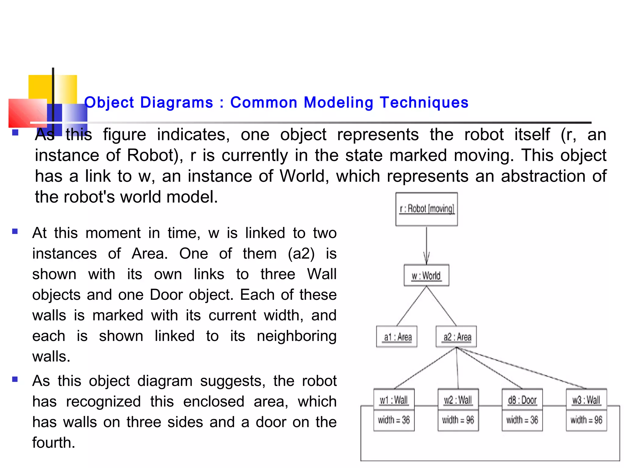
 Object Diagram :
 It is a diagram that shows a set of objects and their relationships at a
point in time.
 Graphically, an object diagram is a collection of vertices and arcs.
 Common Properties :
 An object diagram is a special kind of diagram and shares the same
common properties as all other diagrams that is,
1. name and
2. graphical contents that are a projection into a model.
 What distinguishes an object diagram from all other kinds of diagrams ?
 It is its particular content.
1
Object Diagrams : Terms & Concepts
 Contents :
 Object diagrams commonly contain
1. Objects 2. Links
 Like all other diagrams, object diagrams may contain notes & constraints.
Note : Sometimes you'll want to place classes in your object diagrams as well,
especially when you want to visualize the classes behind each instance.
Note : Object diagram correlates with a class diagram.
 Class diagram : It describes the general situation and the instance diagram
describes specific instances derived from the class diagram.
 Object diagram : contains primarily objects and links.
Note : Deployment diagrams may also occur in generic and instance forms.
 General deployment diagrams describe node types.
 Instance deployment diagrams describe a concrete configuration of node
instances described by those types.
2
Object Diagrams : Terms & Concepts
Object Diagrams : Common Modeling Techniques
 To model an Object structure :
1. Identify the mechanism you'd like to model. A mechanism represents some
function or behavior of the part of the system you are modeling that results
from the interaction of a society of classes, interfaces, and other things.
2. Create a collaboration to describe a mechanism.
3. For each mechanism, identify the classes, interfaces, and other elements
that participate in this collaboration; identify the relationships among these
things as well.
4. Consider one scenario that walks through this mechanism. Freeze that
scenario at a moment in time, and render each object that participates in
the mechanism.
5. Expose the state and attribute values of each such object, as necessary, to
understand the scenario.
6. Similarly, expose the links among these objects, representing instances of
associations among them. 3
 As this figure indicates, one object represents the robot itself (r, an
instance of Robot), r is currently in the state marked moving. This object
has a link to w, an instance of World, which represents an abstraction of
the robot's world model.
4
 At this moment in time, w is linked to two
instances of Area. One of them (a2) is
shown with its own links to three Wall
objects and one Door object. Each of these
walls is marked with its current width, and
each is shown linked to its neighboring
walls.
 As this object diagram suggests, the robot
has recognized this enclosed area, which
has walls on three sides and a door on the
fourth.
Object Diagrams : Common Modeling Techniques
 Reverse Engineering : To reverse engineer an object diagram,
1. Chose the target you want to reverse engineer. Typically, you'll set your context
inside an operation or relative to an instance of one particular class.
2. Using a tool or simply walking through a scenario, stop execution at a certain
moment in time.
3. Identify the set of interesting objects that collaborate in that context and render them
in an object diagram.
4. As necessary to understand their semantics, expose these object's states.
5. As necessary to understand their semantics, identify the links that exist among these
objects.
6. If your diagram ends up overly complicated, prune it by eliminating objects that are
not germane to the questions about the scenario you need answered. If your
diagram is too simplistic, expand the neighbors of certain interesting objects and
expose each object's state more deeply.
7. You will usually have to manually add or label structure that is not explicit in the
target code. The missing information supplies the design intent that is only implicit in
the final code.
5
Object Diagrams : Common Modeling Techniques
Object Diagrams : Hints & Tips
 A well-structured object diagram
1. Is focused on communicating one aspect of a system's static design view
or static process view.
2. Represents one frame in the dynamic storyboard represented by an
interaction diagram.
3. Contains only those elements that are essential to understanding that
aspect.
4. Provides detail consistent with its level of abstraction; you should expose
only those attribute values and other adornments that are essential to
understanding.
5. Is not so minimalist as to misinform the reader about semantics that are
important.
6
Object Diagrams : Hints & Tips
 When you draw an object diagram,
1. Give it a name that communicates its purpose.
2. Lay out its elements to minimize lines that cross.
3. Organize its elements spatially so that things that are semantically close
are laid out to be physically close.
4. Use notes and color as visual cues to draw attention to important features
of your diagram.
5. Include the values and state of each object as necessary to communicate
your intent.
7

Fundamentals of Software Engineering

  • 1.
     Object Diagram:  It is a diagram that shows a set of objects and their relationships at a point in time.  Graphically, an object diagram is a collection of vertices and arcs.  Common Properties :  An object diagram is a special kind of diagram and shares the same common properties as all other diagrams that is, 1. name and 2. graphical contents that are a projection into a model.  What distinguishes an object diagram from all other kinds of diagrams ?  It is its particular content. 1 Object Diagrams : Terms & Concepts
  • 2.
     Contents : Object diagrams commonly contain 1. Objects 2. Links  Like all other diagrams, object diagrams may contain notes & constraints. Note : Sometimes you'll want to place classes in your object diagrams as well, especially when you want to visualize the classes behind each instance. Note : Object diagram correlates with a class diagram.  Class diagram : It describes the general situation and the instance diagram describes specific instances derived from the class diagram.  Object diagram : contains primarily objects and links. Note : Deployment diagrams may also occur in generic and instance forms.  General deployment diagrams describe node types.  Instance deployment diagrams describe a concrete configuration of node instances described by those types. 2 Object Diagrams : Terms & Concepts
  • 3.
    Object Diagrams :Common Modeling Techniques  To model an Object structure : 1. Identify the mechanism you'd like to model. A mechanism represents some function or behavior of the part of the system you are modeling that results from the interaction of a society of classes, interfaces, and other things. 2. Create a collaboration to describe a mechanism. 3. For each mechanism, identify the classes, interfaces, and other elements that participate in this collaboration; identify the relationships among these things as well. 4. Consider one scenario that walks through this mechanism. Freeze that scenario at a moment in time, and render each object that participates in the mechanism. 5. Expose the state and attribute values of each such object, as necessary, to understand the scenario. 6. Similarly, expose the links among these objects, representing instances of associations among them. 3
  • 4.
     As thisfigure indicates, one object represents the robot itself (r, an instance of Robot), r is currently in the state marked moving. This object has a link to w, an instance of World, which represents an abstraction of the robot's world model. 4  At this moment in time, w is linked to two instances of Area. One of them (a2) is shown with its own links to three Wall objects and one Door object. Each of these walls is marked with its current width, and each is shown linked to its neighboring walls.  As this object diagram suggests, the robot has recognized this enclosed area, which has walls on three sides and a door on the fourth. Object Diagrams : Common Modeling Techniques
  • 5.
     Reverse Engineering: To reverse engineer an object diagram, 1. Chose the target you want to reverse engineer. Typically, you'll set your context inside an operation or relative to an instance of one particular class. 2. Using a tool or simply walking through a scenario, stop execution at a certain moment in time. 3. Identify the set of interesting objects that collaborate in that context and render them in an object diagram. 4. As necessary to understand their semantics, expose these object's states. 5. As necessary to understand their semantics, identify the links that exist among these objects. 6. If your diagram ends up overly complicated, prune it by eliminating objects that are not germane to the questions about the scenario you need answered. If your diagram is too simplistic, expand the neighbors of certain interesting objects and expose each object's state more deeply. 7. You will usually have to manually add or label structure that is not explicit in the target code. The missing information supplies the design intent that is only implicit in the final code. 5 Object Diagrams : Common Modeling Techniques
  • 6.
    Object Diagrams :Hints & Tips  A well-structured object diagram 1. Is focused on communicating one aspect of a system's static design view or static process view. 2. Represents one frame in the dynamic storyboard represented by an interaction diagram. 3. Contains only those elements that are essential to understanding that aspect. 4. Provides detail consistent with its level of abstraction; you should expose only those attribute values and other adornments that are essential to understanding. 5. Is not so minimalist as to misinform the reader about semantics that are important. 6
  • 7.
    Object Diagrams :Hints & Tips  When you draw an object diagram, 1. Give it a name that communicates its purpose. 2. Lay out its elements to minimize lines that cross. 3. Organize its elements spatially so that things that are semantically close are laid out to be physically close. 4. Use notes and color as visual cues to draw attention to important features of your diagram. 5. Include the values and state of each object as necessary to communicate your intent. 7