Three Phase AC Controller by using thyristor .pptx
1.
Three-Phase AC Controller
PowerElectronics & Control Systems
Thyristor-based AC Voltage Regulation
Power Systems Engineering • 2025
2.
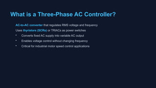
What is aThree-Phase AC Controller?
AC-to-AC converter that regulates RMS voltage and frequency
Uses thyristors (SCRs) or TRIACs as power switches
• Converts fixed AC supply into variable AC output
• Enables voltage control without changing frequency
• Critical for industrial motor speed control applications
3.
Main Components
Power Devices
Thyristors(SCR) or TRIACs for switching
Gate Circuit
Controls firing angle of power devices
Load Impedance
Resistive or inductive load
4.
Operating Principle
Phase ControlMethod:
• Thyristor turns ON at specific point (firing angle α) during half-cycle
• Turns OFF when voltage naturally crosses zero
• Varying firing angle α controls output voltage
RMS output voltage: V = V × √[(π - α + ½sin(2α))/π]
5.
Three-Phase Controller Topologies(Part 1)
Star (Y) Connection:
• Four-wire system: R, Y, B phases + neutral
• Each phase controlled independently
• Simple analysis using single-phase principles
• Neutral current contains triplet harmonics
6.
Three-Phase Controller Topologies(Part 2)
Delta (Δ) Connection:
• Three-wire system (no neutral required)
• Each controller placed in line between phases
• Back-to-back thyristor pair per phase
• More compact design, no triplet harmonics
Firing Circuits (Part1)
R Firing Circuit:
• Simplest method using variable resistance R
• AC supply given to gate terminal
• Firing angle range: 0° to 90°
• Limited control range but low cost
10.
Firing Circuits (Part2)
RC Firing Circuit:
• Capacitor charges through variable resistor R
• Two types: Half-wave and Full-wave RC
• Greater control range (0° to 180°)
• More complex but better performance
11.
Firing Angle &Output Waveforms
Output voltage varies with firing angle α
12.
Load Characteristics (Part1)
Resistive Load (R):
• Current and voltage waveforms are in phase
• Load impedance: Z = R (constant)
• Power factor: PF = 1 (unity)
• Examples: heating elements, incandescent lights
13.
Load Characteristics (Part2)
Inductive Load (RL):
• Current lags voltage by angle φ
Load impedance: Z = √(R² + X²)
• Power factor: PF = cos(φ) < 1
• Examples: motors, transformers, inductors
Power Factor Considerations
KeyObservations:
• PF = 1.0 at full output (100% voltage)
• PF decreases as output voltage reduces
• At 50% output: PF ≈ 0.5 (phase angle control)
• Affects apparent power and current requirements
16.
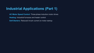
Industrial Applications (Part1)
AC Motor Speed Control: Three-phase induction motor drives
Heating: Industrial furnaces and heater control
Soft Starters: Reduced inrush current on motor startup
Firing Methods Comparison
ZeroCrossover (Burst Pulse):
Thyristors switch ON/OFF only at zero voltage crossover points
Phase Angle Firing:
Thyristors switch ON at any point during half-cycle for smooth control
Design Considerations
Thyristor Rating:Peak inverse voltage, average current, power dissipation
Heat Management: Proper cooling and thermal design
Snubber Circuits: Protect from voltage spikes during switching
Gate Drive: Adequate gate current and pulse width
21.
Three-Phase Star ACVoltage Controller
Three independent single-phase controllers in Y-configuration
22.
Three-Phase Delta ACVoltage Controller
Back-to-back thyristors in line connections between phases
23.
RMS Output VoltageFormula
V = V √[(π - α + ½sin(2α)) / (2π)]
Where:
V = Peak supply voltage
• α = Firing angle (delay angle) in radians
• Range: 0 ≤ α ≤ π
24.
MATLAB/Simulink Simulation
Key SimulationSteps:
• Model three-phase AC source (3 × 120° phase shift)
• Implement thyristor gate logic with firing angle control
• Measure output voltage and current waveforms
• Analyze harmonics using FFT
• Visualize power factor variation with load
25.
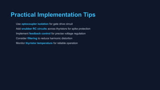
Practical Implementation Tips
Useoptocoupler isolation for gate drive circuit
Add snubber RC circuits across thyristors for spike protection
Implement feedback control for precise voltage regulation
Consider filtering to reduce harmonic distortion
Monitor thyristor temperature for reliable operation
26.
Key Takeaways
Three-phase ACcontrollers are essential for industrial power control
Thyristor-based phase control enables efficient voltage regulation
Understanding firing circuits, topologies, and harmonic effects is crucial for design

![Operating Principle
Phase Control Method:
• Thyristor turns ON at specific point (firing angle α) during half-cycle
• Turns OFF when voltage naturally crosses zero
• Varying firing angle α controls output voltage
RMS output voltage: V = V × √[(π - α + ½sin(2α))/π]](https://image.slidesharecdn.com/threephaseaccontroller-251218104201-10558542/85/Three-Phase-AC-Controller-by-using-thyristor-pptx-4-320.jpg)


![RMS Output Voltage Formula
V = V √[(π - α + ½sin(2α)) / (2π)]
Where:
V = Peak supply voltage
• α = Firing angle (delay angle) in radians
• Range: 0 ≤ α ≤ π](https://image.slidesharecdn.com/threephaseaccontroller-251218104201-10558542/85/Three-Phase-AC-Controller-by-using-thyristor-pptx-23-320.jpg)