Downloaded 19 times


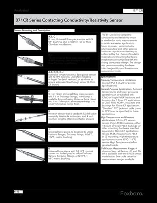
![Flow (Vortex Flowmeters)
3
84
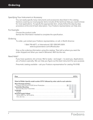
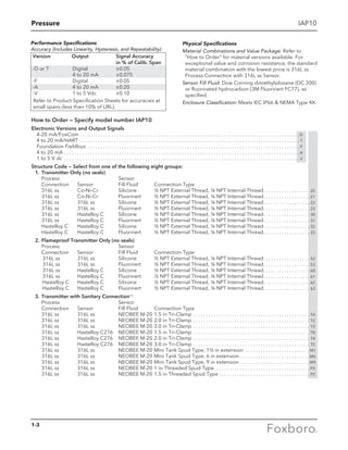
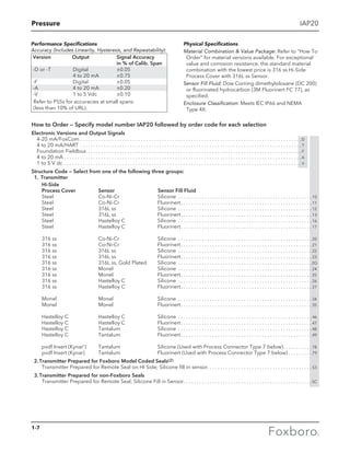
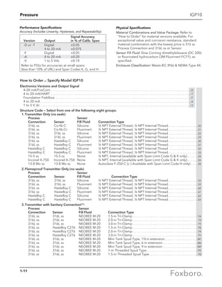
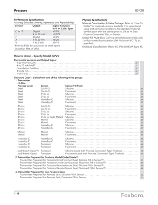
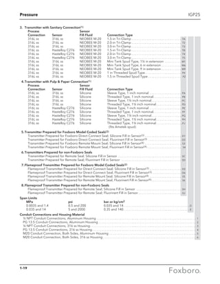
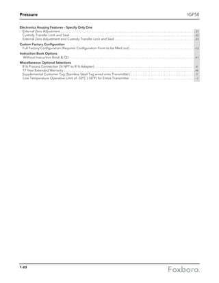
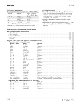
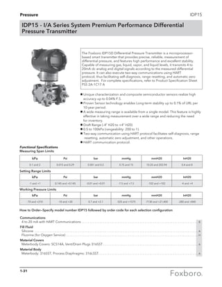
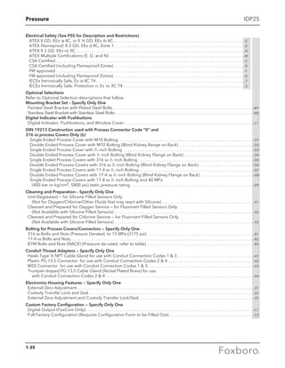
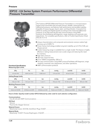
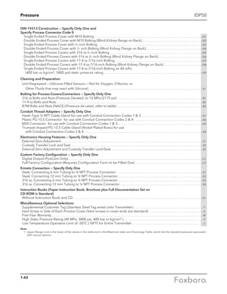
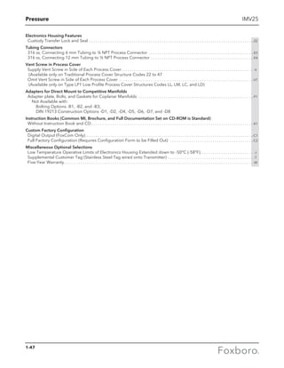
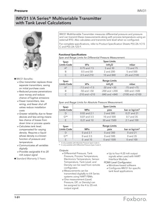
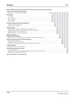
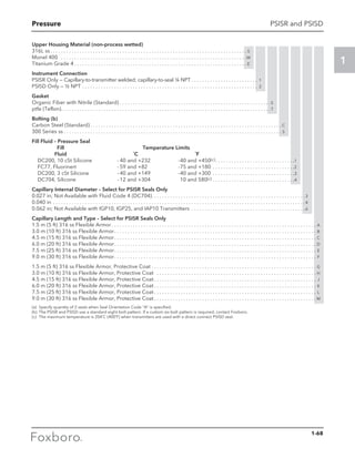
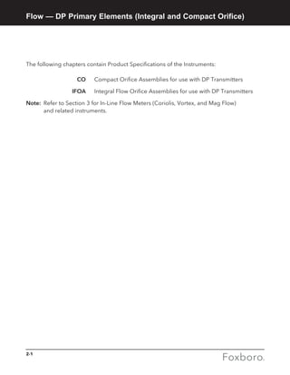
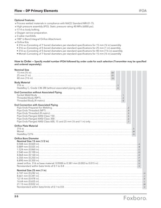
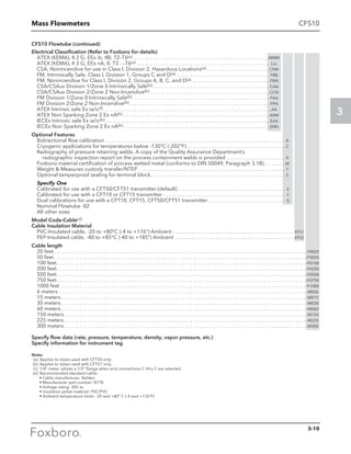
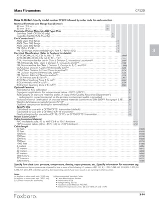
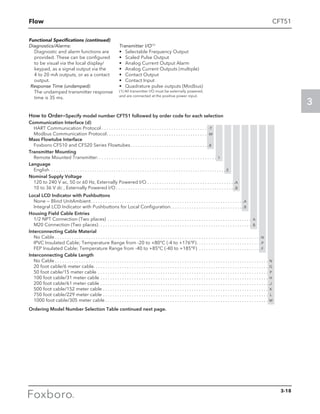
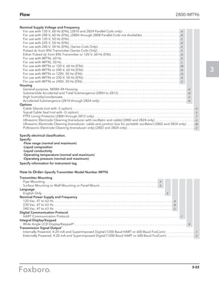
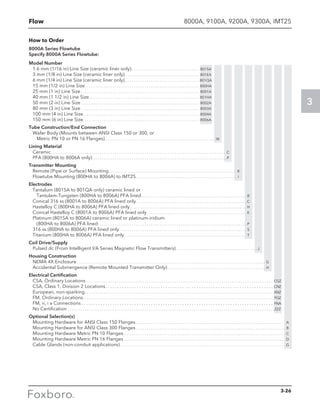
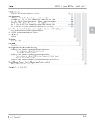
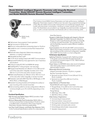
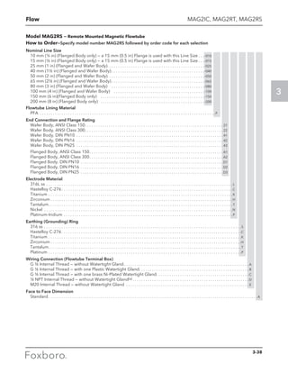
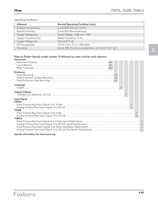
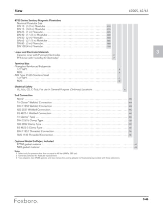
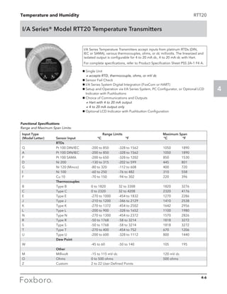
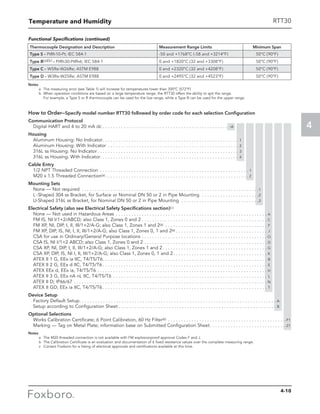
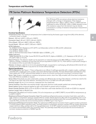
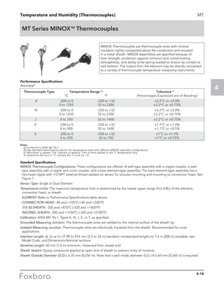
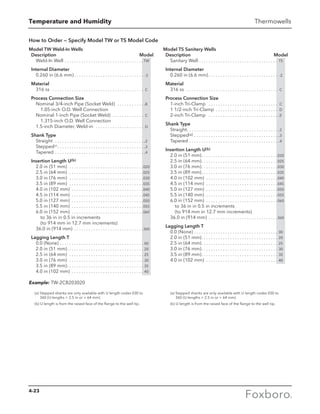
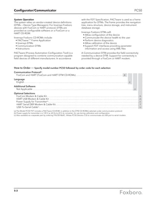
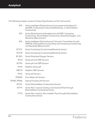
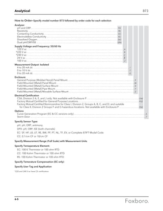
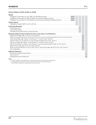
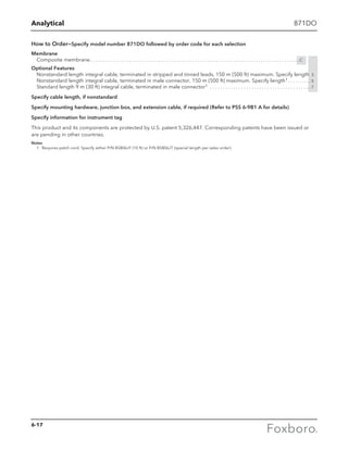
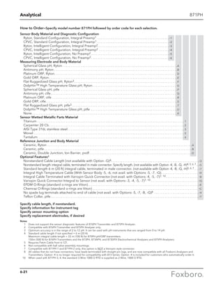
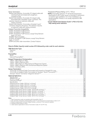
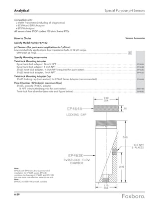
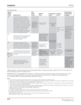
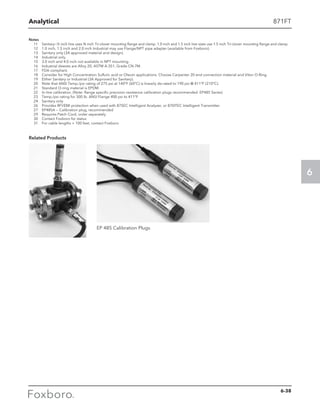
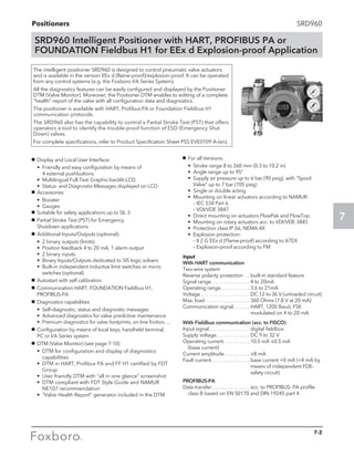
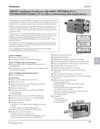
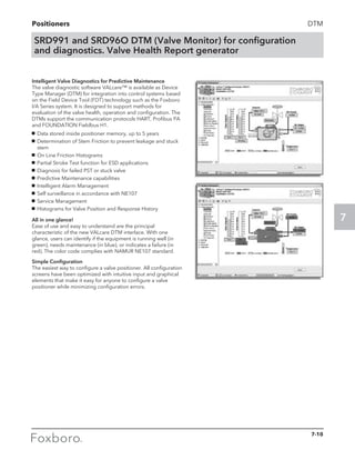
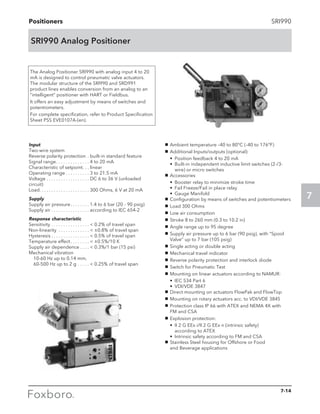
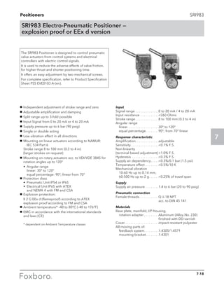
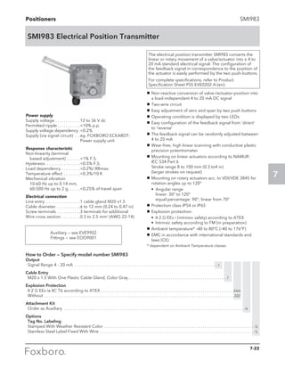
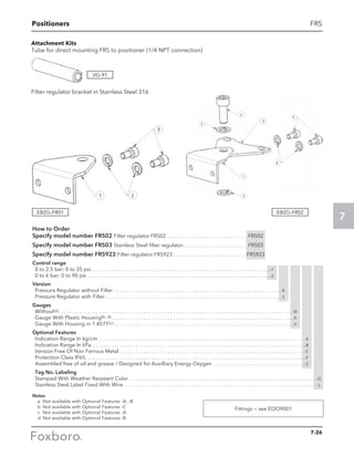
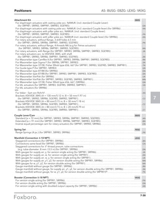
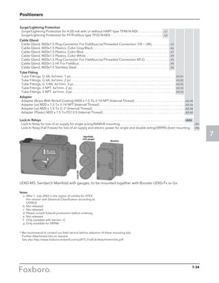
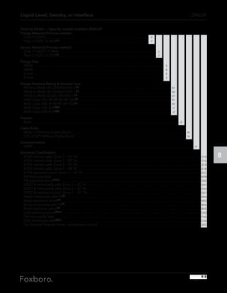
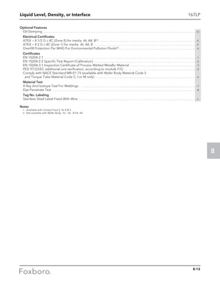
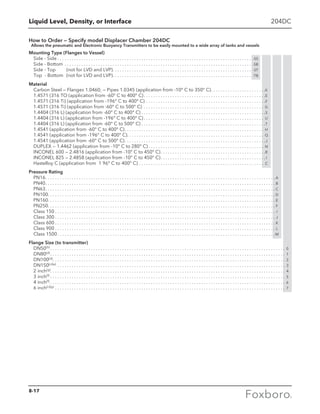
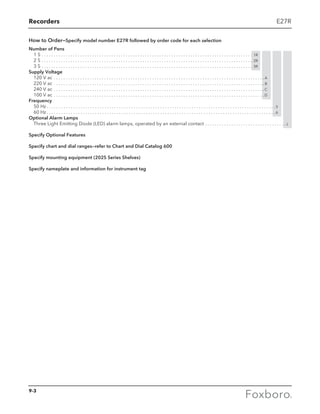
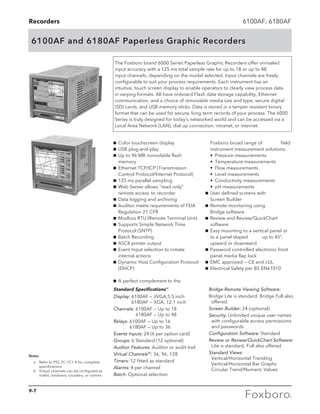
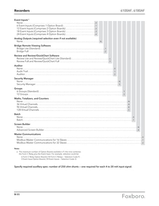
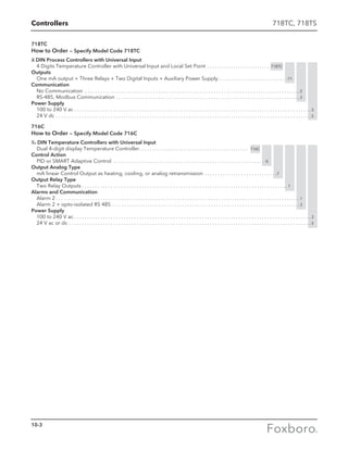
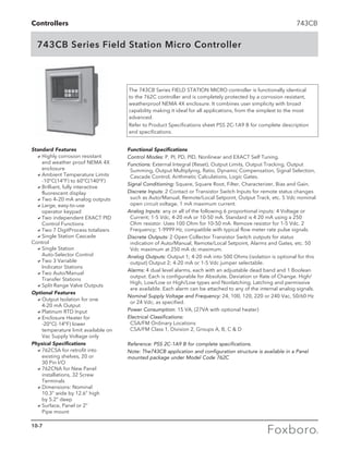
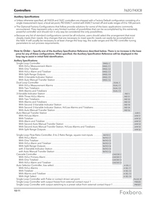
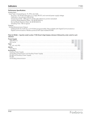
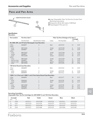
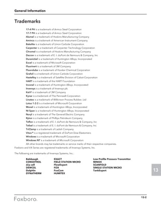
84F Flanged Version (continued)
Local Digital Indicator/Configurator
No Digital Indicator/Configurator (Blind Unit) . . . . . . . . . . . . . . . . . . . . . . . . . . . . . . . . . . . . . . . . . . . . . . . . . . . . . . . N
Full Function Digital Indicator/Configurator . . . . . . . . . . . . . . . . . . . . . . . . . . . . . . . . . . . . . . . . . . . . . . . . . . . . . . . . . . J
Electrical Safety (Also see Electrical Safety Specifications section for further details)
ATEX intrinsically Safe; II 1G II 2D Ex ia IIC T4 Ga Ex tb IIIC T103°C Db; not available with Mounting Codes T and R . . . . . . . . . E
ATEX flameproof; not available with Mounting Codes T and R: . . . . . . . . . . . . . . . . . . . . . . . . . . . . . . . . . . . . . . . . . . . . . . . . . . . . . . . . . H
For II 2/1 (1) G II 2D Ex d [ia Ga] ia IIC T4 Gb Ex tb IIIC T85°C Db; available with Mounting Code V only
For II 2/1 (1) G II 2D Ex d [ia Ga] IIC T4 Gb Ex tb IIIC T85°C Db; available with Mounting Code W only
For II 1G II 2D Ex ia IIC T4 Ga Ex tb IIIC T103°C Db; available with Mounting Code W only
CSA intrinsically safe; Division 1; also zone certified Ex ia IIC. . . . . . . . . . . . . . . . . . . . . . . . . . . . . . . . . . . . . . . . . . . . . . . . . . . . . . . . . . . . C
CSA nonincendive; Division 2. . . . . . . . . . . . . . . . . . . . . . . . . . . . . . . . . . . . . . . . . . . . . . . . . . . . . . . . . . . . . . . . . . . . . . . . . . . . . . . . . . . . . . . . M
CSA explosionproof; Division 1 . . . . . . . . . . . . . . . . . . . . . . . . . . . . . . . . . . . . . . . . . . . . . . . . . . . . . . . . . . . . . . . . . . . . . . . . . . . . . . . . . . . . . . D
FM intrinsically safe; Division 1; also zone approved AEx ia IIC. . . . . . . . . . . . . . . . . . . . . . . . . . . . . . . . . . . . . . . . . . . . . . . . . . . . . . . . . . F
FM nonincendive; Division 2. . . . . . . . . . . . . . . . . . . . . . . . . . . . . . . . . . . . . . . . . . . . . . . . . . . . . . . . . . . . . . . . . . . . . . . . . . . . . . . . . . . . . . . . . K
FM explosionproof; Division 1. . . . . . . . . . . . . . . . . . . . . . . . . . . . . . . . . . . . . . . . . . . . . . . . . . . . . . . . . . . . . . . . . . . . . . . . . . . . . . . . . . . . . . . . G
IECEx intrinsically safe; Ex ia IIC T4 Ga Ex tb IIIC T103°C Db; not available with Mounting Codes T and R. . . . . . . . . . . . . . . . . . . L
IECEx flameproof; not available with Mounting Codes T and R: . . . . . . . . . . . . . . . . . . . . . . . . . . . . . . . . . . . . . . . . . . . . . . . . . . . . . . . . . B
For Ex d [ia Ga] ia IIC T4 Gb Ex tb IIIC T85°C Db; available with Mounting Code V only
For Ex d [ia Ga] IIC T4 Gb Ex tb IIIC T85°C Db; available with Mounting Code W only
For Ex ia IIC T4 Ga Ex tb IIIC T103°C Db; available with Mounting Code W only
NEPSI intrinsically safe, Zone 0, Ex ia IIC; not available with Mounting Codes T and R . . . . . . . . . . . . . . . . . . . . . . . . . . . . . . . . . . . . . R
NEPSI flameproof, Zone 1, Ex d IIC; not available with Mounting Codes T and R. . . . . . . . . . . . . . . . . . . . . . . . . . . . . . . . . . . . . . . . . . S
No Agency Electrical Certifications; with CE mark, PED Controls and Records. . . . . . . . . . . . . . . . . . . . . . . . . . . . . . . . . . . . . . . . . . . . Y
No Agency Certifications; no CE mark; Units not to be installed in European Union (EU) countries. . . . . . . . . . . . . . . . . . . . . . . . . Z
Optional Selections
Cable Length Selection for Remote Electronics Housing
20 ft (6 m) Cable to Connect to Remote Electronics Housing . . . . . . . . . . . . . . . . . . . . . . . . . . . . . . . . . . . . . . . . . . . . . . . . . . . -B
30 ft (9 m) Cable to Connect to Remote Electronics Housing . . . . . . . . . . . . . . . . . . . . . . . . . . . . . . . . . . . . . . . . . . . . . . . . . . -D
40 ft (12 m) Cable to Connect to Remote Electronics Housing . . . . . . . . . . . . . . . . . . . . . . . . . . . . . . . . . . . . . . . . . . . . . . . . . . -E
50 ft (15 m) Cable to Connect to Remote Electronics Housing . . . . . . . . . . . . . . . . . . . . . . . . . . . . . . . . . . . . . . . . . . . . . . . . . -G
Cleaning — Oxygen/Chlorine Service
Cleaning of Process Wetted Parts per Compressed Gas Association’s CGA G-4.1 and ASTM G93 . . . . . . . . . . . . . . . . . -H
Available only with Body/Flange/Shedder Material Code R and Y.
Not available with Line Sizes 10 and 12 or with Isolation Valve Codes D, K, and L.
Not available with Extended Temperature Codes E and G.
Sensor Plating
Gold Plated Sensor . . . . . . . . . . . . . . . . . . . . . . . . . . . . . . . . . . . . . . . . . . . . . . . . . . . . . . . . . . . . . . . . . . . . . . . . . . . . . . . . . . . . . . . -J
Foxboro Certificates of Compliance/Conformance
Standard Certificate of Compliance . . . . . . . . . . . . . . . . . . . . . . . . . . . . . . . . . . . . . . . . . . . . . . . . . . . . . . . . . . . . . . . . . . . . . . . . . -L
Foxboro Material Certification of Process Wetted Metal (Conforms to BS EN 10204 3.1) . . . . . . . . . . . . . . . . . . . . . . . . . . -M
Process Wetted Parts Conform to NACE Standard MR-01 . . . . . . . . . . . . . . . . . . . . . . . . . . . . . . . . . . . . . . . . . . . . . . . . . . . . . -Q
Foxboro Calibration Certificate
Calibration and Pressure Test Certified Copy . . . . . . . . . . . . . . . . . . . . . . . . . . . . . . . . . . . . . . . . . . . . . . . . . . . . . . . . . . . . . . . -N
Cable Connectors – with Electrical Housing Codes T and R only (1/2 NPT)
Hawke-Type Cable Gland (Available only with Electrical Safety Codes E, H, Y, and Z) . . . . . . . . . . . . . . . . . . . . . . . . . . . . . -P
PG11 Cable Gland, Trumpet Shaped (Not available with explosionproof/flameproof certifications) . . . . . . . . . . . . . . . . . -R
Conduit Fitting
Adapter for use with 1/2 NPT conduit (Available with Remote Mounted Housing Code R only) . . . . . . . . . . . . . . . . . . . . . -T
Welding Certificate (Size Codes 06 through 12 only)
Welding certified to conform to ASME Boiler and Pressure Vessel Code, Section IX . . . . . . . . . . . . . . . . . . . . . . . . . . . . . . -F
Radiographic Examination (X-Ray) of Flange Welds . . . . . . . . . . . . . . . . . . . . . . . . . . . . . . . . . . . . . . . . . . . . . . . . . . . . . . . . . . . -V
Welding certified to conform to ASME Boiler and Pressure Vessel Code, Section IX and Radiographic Examination (X-Ray) of welds . . -X
Instruction Manual
Detailed Instruction Manual in place of Universal MI 019-145 . . . . . . . . . . . . . . . . . . . . . . . . . . . . . . . . . . . . . . . . . . . . . . . . . -C
Notes
(a) For remote mounting, select optional cable length.
(b) For ATEX and IECEx certifications, select M20.
(c) For Line Sizes 3Q, 01, and 1H, select End Connection H.
(d) See Welding Certificate Option –X for extended temperature range (400° to 800 ° F)(200° to 430° C).
(e) Contact Invensys for availability in Style B.
(f) High Temperature Sensors are not available with Body, Flange, and Shedder Bar Material
selection D (Duplex SS).
(g) For Line Sizes 3Q, 01, and 1H, select End Connection 8.
(h) Only electrical certifications F, K, and G are available with these model codes at this time.
(i) Available with ANSI End Connections 1, 2 and 3 for Line Sizes 3Q through 08, and End
Connections 1 and 2 for Line Sizes 10 and 12.
(j) These versions should only be used when replacing a Model 84F Style A meter or for
stocking purposes for Model 84F Style A meters.
(k) Hastelloy® is a registered trademark of Haynes International Inc.
(l) For Line Size 08 with 4, 9, S, T, K, and M End Connections, Welding Certificate Option -X is required.
3-4](https://image.slidesharecdn.com/catalogfoxboromeasuremeandinstruments01-13-150912171749-lva1-app6891/85/Foxboro-Measurement-and-Control-Instruments-89-320.jpg)
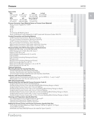
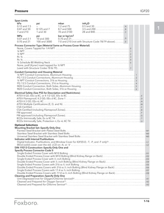
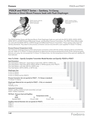
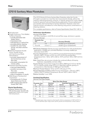
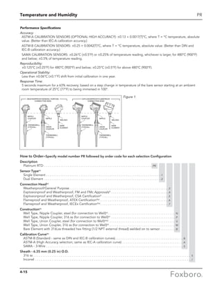
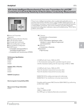
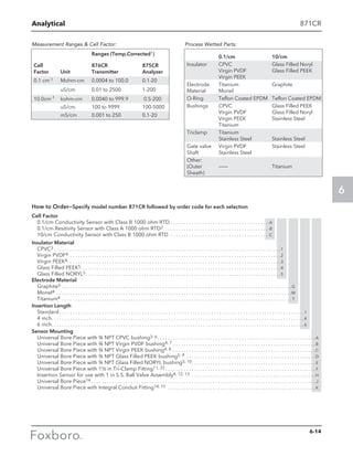
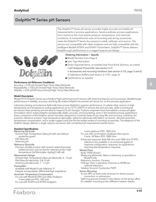
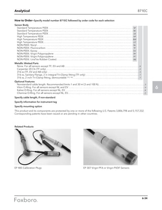
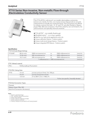
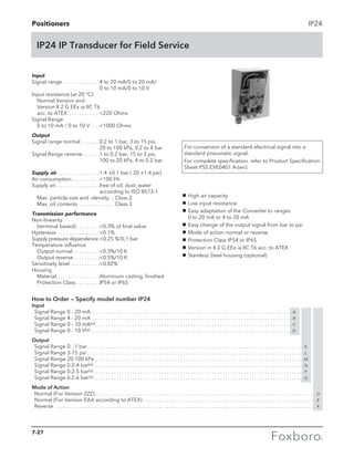
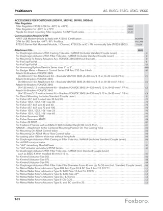
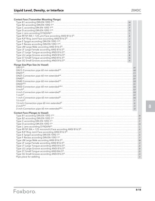
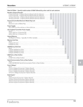
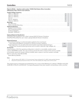
![Flow (Vortex Flowmeters)
3
84
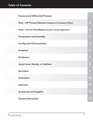
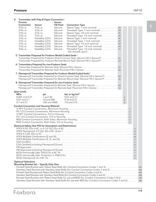
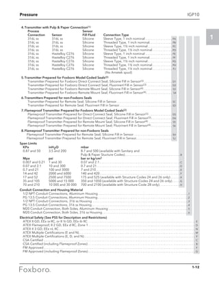
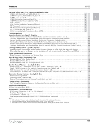
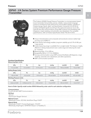
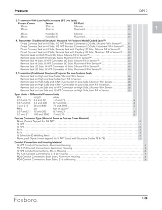
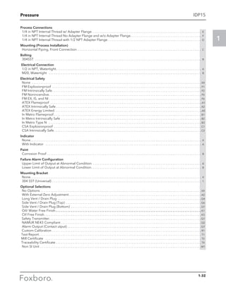
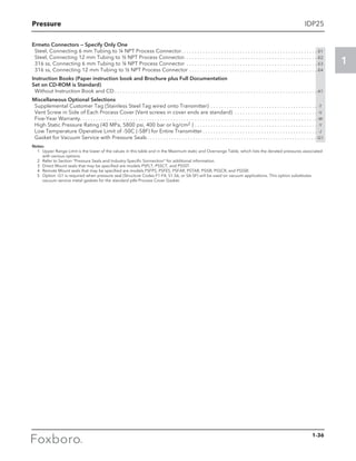
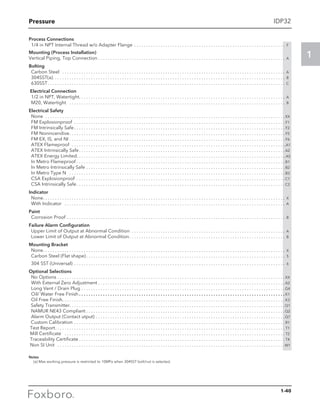
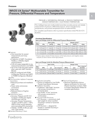
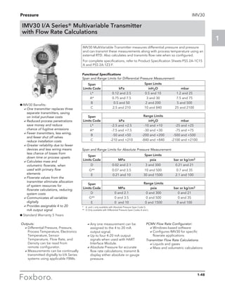
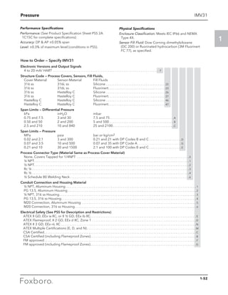
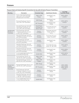
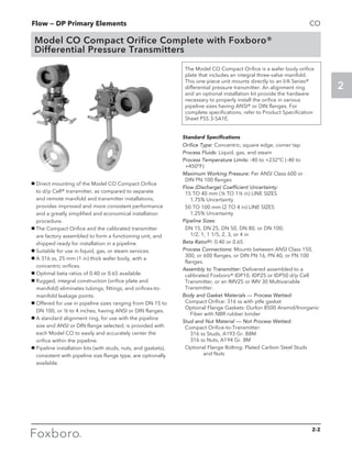
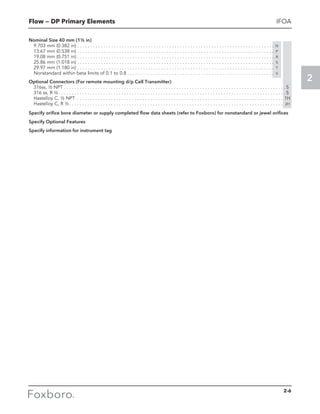
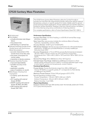
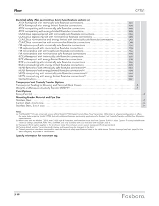
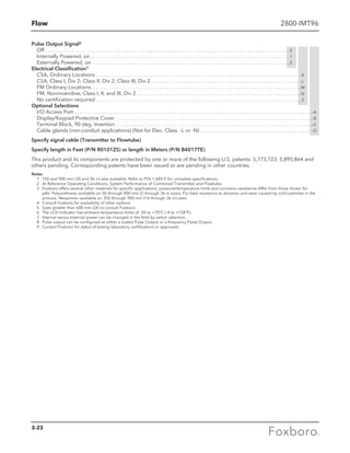
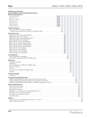
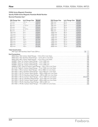
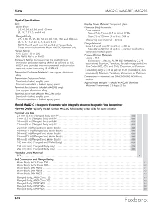
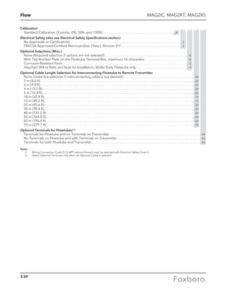
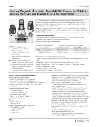
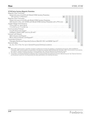
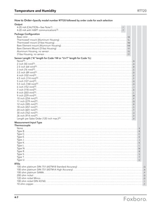
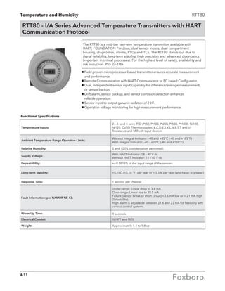
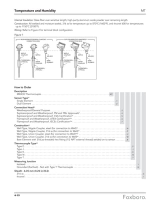
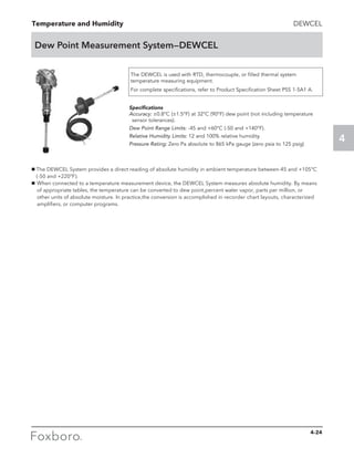
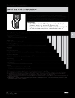
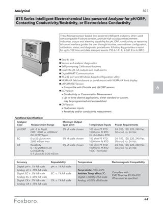
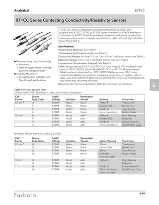
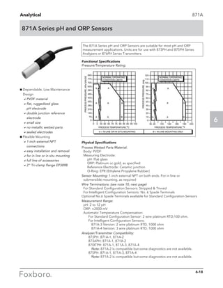
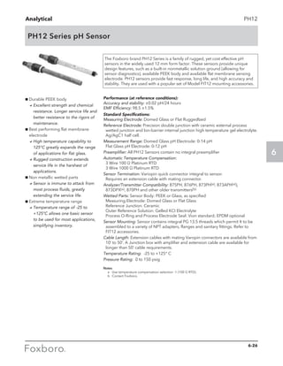
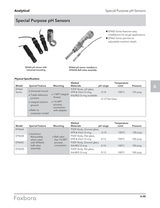
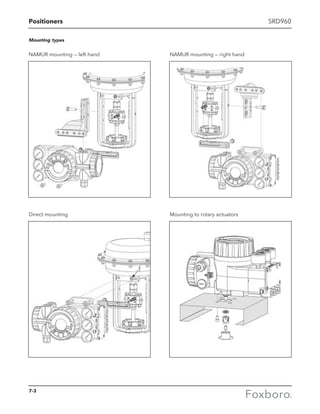
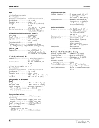
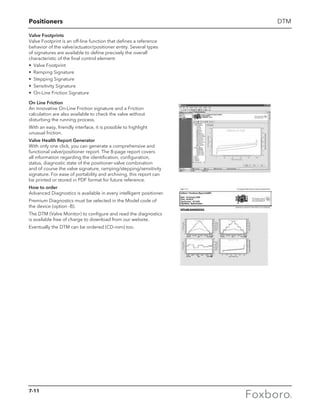
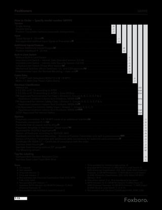
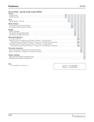
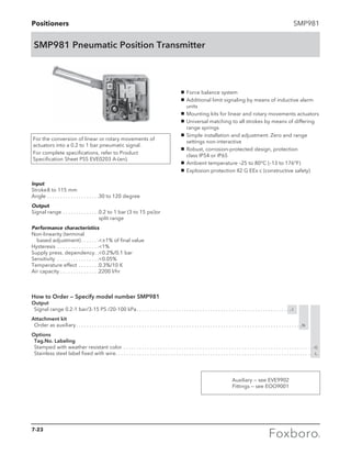
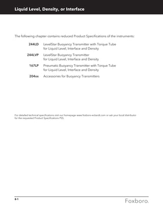
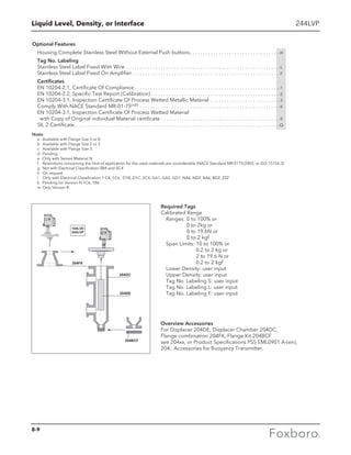
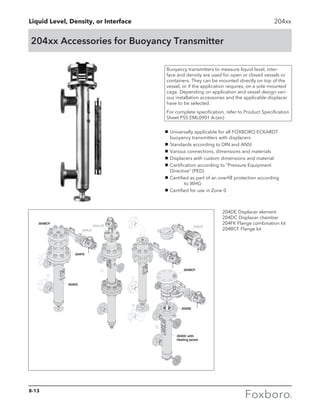
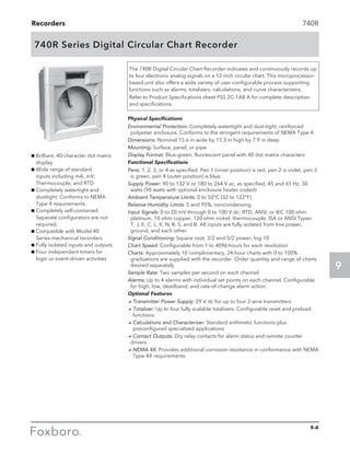
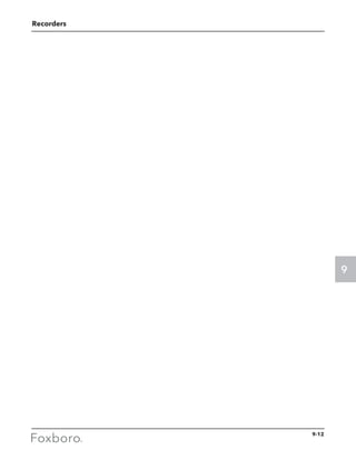
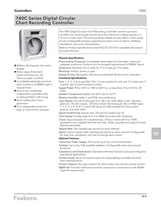
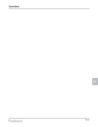
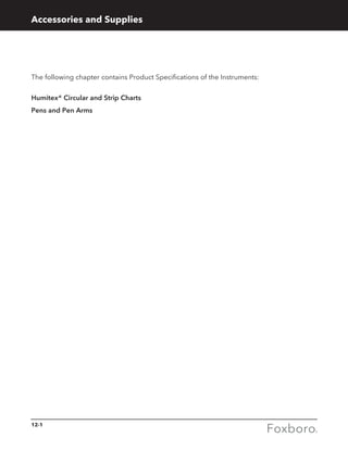
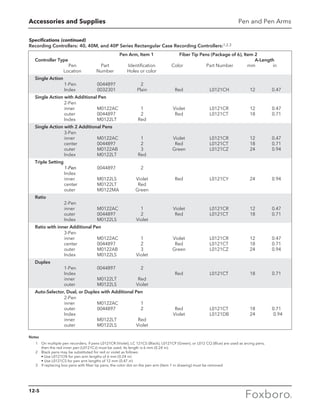
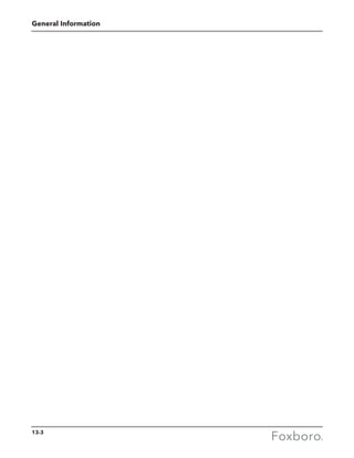
84W: Wafer Version (continued)
Electrical Safety (Also see Electrical Safety Specifications section for further details)
ATEX intrinsically Safe; II 1 GD, EEx ia IIC; T4
(not available with mounting Codes T and R). . . . . . . . . . . . . . . . . . . . . . . . . . . . . . . . . . . . . . . . . . E
ATEX flameproof: . . . . . . . . . . . . . . . . . . . . . . . . . . . . . . . . . . . . . . . . . . . . . . . . . . . . . . . . . . . . . . . . . . . H
for II 2/1 (1) GD, EEx d [ia] ia, T4; with Mounting Code V only.
for II 2 (1) GD, EEx d [ia], T4; with Mounting Code W only.
for II 1 GD, EEx ia IIC; T4; with Mounting Code W only.
CSA intrinsically safe; Division 1; T4. . . . . . . . . . . . . . . . . . . . . . . . . . . . . . . . . . . . . . . . . . . . . . . . . . . C
CSA Nonincendive; Division 2, T4. . . . . . . . . . . . . . . . . . . . . . . . . . . . . . . . . . . . . . . . . . . . . . . . . . . . . M
CSA explosionproof; Division 1; T5 . . . . . . . . . . . . . . . . . . . . . . . . . . . . . . . . . . . . . . . . . . . . . . . . . . . D
FM intrinsically safe; Division 1; T4 . . . . . . . . . . . . . . . . . . . . . . . . . . . . . . . . . . . . . . . . . . . . . . . . . . . . F
FM nonincendive; Division 2, T4. . . . . . . . . . . . . . . . . . . . . . . . . . . . . . . . . . . . . . . . . . . . . . . . . . . . . . K
FM explosionproof; Division 1; T5. . . . . . . . . . . . . . . . . . . . . . . . . . . . . . . . . . . . . . . . . . . . . . . . . . . . . G
IECEx intrinsically safe; Ex ia IIC, T4; Dust-ignitionproof Ex tD A20, IP66
(not available with . . . . . . . . . . . . . . . . . . . . . . . . . . . . . . . . . . . . . . . . . . . . . . . . . . . . . . . . . . . . . . . . . L
Mounting Codes T and R).
IECEx flameproof: . . . . . . . . . . . . . . . . . . . . . . . . . . . . . . . . . . . . . . . . . . . . . . . . . . . . . . . . . . . . . . . . . . B
Ex d [ia] ia IIC; Dust-ignitionproof Ex tD A20, IP66; with Mounting Code V only.
Ex d [ia]; Dust-ignitionproof Ex tD A20, IP66; with Mounting Code W only.
Ex ia IIC; Dust-ignitionproof Ex tD A20, IP66; with Mounting Code W only.
NEPSI intrinsically safe, Zone 0, Ex ia IIC (not with mounting codes T and R) . . . . . . . . . . . . . . . R
NEPSI flameproof, Zone 1, Ex d IIC (not with mounting codes T and R) . . . . . . . . . . . . . . . . . . . . S
No Agency Electrical Certifications; (with CE mark, PED Controls and Records). . . . . . . . . . . . . Y
No Agency Certifications; (no CE mark;
Units not to be installed in European Union (EU) countries). . . . . . . . . . . . . . . . . . . . . . . . . . . . . . Z
Optional Selections
Cable Length Selection for Remote Electronics Housing
20 ft (6 m) Cable to Connect to Remote Electronics Housing . . . . . . . . . . . . . . . . . . . . . . . . . . . . . . . . . . . . . -B
30 ft (9 m) Cable to Connect to Remote Electronics Housing . . . . . . . . . . . . . . . . . . . . . . . . . . . . . . . . . . . . . -D
40 ft (12 m) Cable to Connect to Remote Electronics Housing . . . . . . . . . . . . . . . . . . . . . . . . . . . . . . . . . . . . -E
50 ft (15 m) Cable to Connect to Remote Electronics Housing . . . . . . . . . . . . . . . . . . . . . . . . . . . . . . . . . . . . -G
Cleaning - Oxygen/Chlorine Service
Cleaning of Process Wetted Parts per Compressed Gas Association’s CGA G-4.1 and ASTM G93 . . . . -H
Not available with Isolation Valve Code K or Sensor Codes C and T
Sensor Plating
Gold Plated Sensor . . . . . . . . . . . . . . . . . . . . . . . . . . . . . . . . . . . . . . . . . . . . . . . . . . . . . . . . . . . . . . . . . . . . . . . . . -J
Foxboro Certificates of Compliance/Conformance
Standard Certificate of Compliance . . . . . . . . . . . . . . . . . . . . . . . . . . . . . . . . . . . . . . . . . . . . . . . . . . . . . . . . . . . -L
Material Certification of Process Wetted Metal (Conforms to BS EN 10204 3.1) . . . . . . . . . . . . . . . . . . . . . -M
Process Wetted Parts Conform to NACE Standard MR-01 . . . . . . . . . . . . . . . . . . . . . . . . . . . . . . . . . . . . . . . . -Q
Foxboro Calibration Certificate
Foxboro Calibration and Pressure Test Certified Copy . . . . . . . . . . . . . . . . . . . . . . . . . . . . . . . . . . . . . . . . . . -N
Cable Connectors – with Electrical Housing Codes T and R only (1/2 NPT)
Hawke-Type Cable Gland . . . . . . . . . . . . . . . . . . . . . . . . . . . . . . . . . . . . . . . . . . . . . . . . . . . . . . . . . . . . . . . . . . . . -P
PG11 Cable Gland, Trumpet Shaped . . . . . . . . . . . . . . . . . . . . . . . . . . . . . . . . . . . . . . . . . . . . . . . . . . . . . . . . . .-R
Conduit Fitting
Adapter for use with 1/2 NPT conduit (Available with Remote Mounted Housing Code R only) . . . . . . . -T
Instruction Manual
Detailed Instruction Manual in place of Universal MI 019-145 . . . . . . . . . . . . . . . . . . . . . . . . . . . . . . . . . . . . -C
Notes
(a) With remote mounted electronics housing, you must also select Optional Cable Length -B, -D, E, or G.
(b) Application ALERT: For Extended Temperature Range sensors used in hazardous or volatile gas applications, there is the potential of
fugitive emissions to occur through the sensor vented restrictor if the sensor diaphragm were to fail.
(c) The Low Power Vortex Flowmeter is not available with a 4 to 20 mA output.
3-6](https://image.slidesharecdn.com/catalogfoxboromeasuremeandinstruments01-13-150912171749-lva1-app6891/85/Foxboro-Measurement-and-Control-Instruments-91-320.jpg)
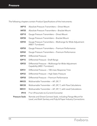
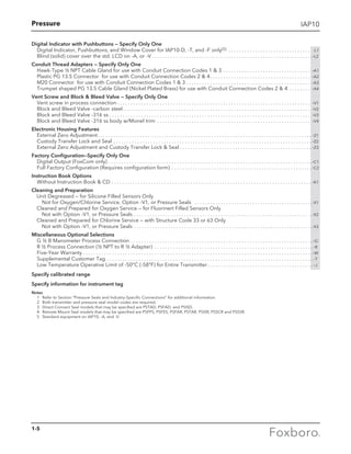
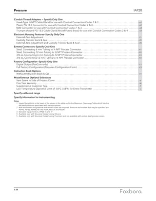
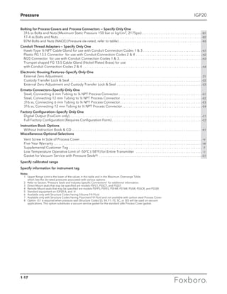
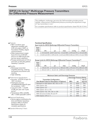
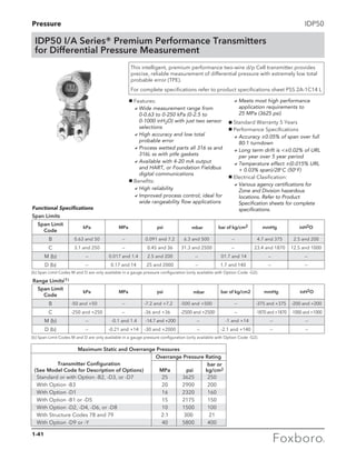
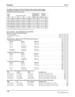
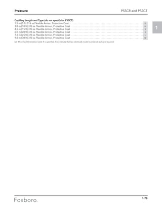
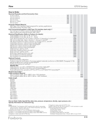
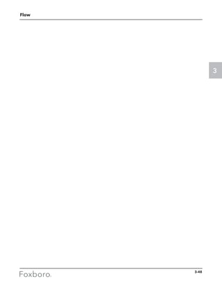
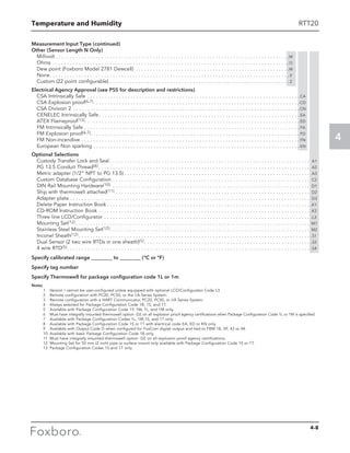
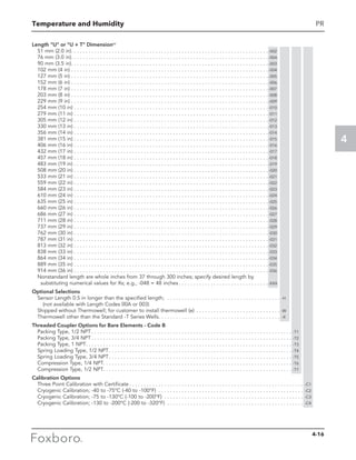
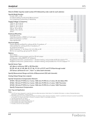
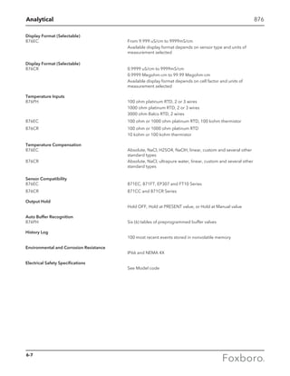
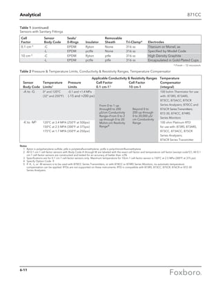
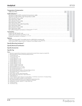
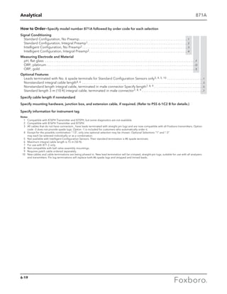
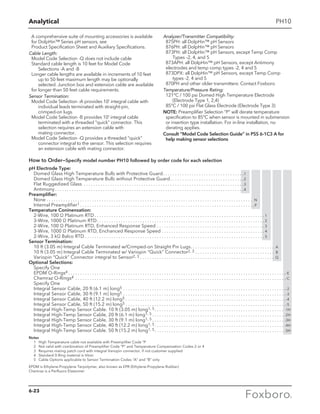
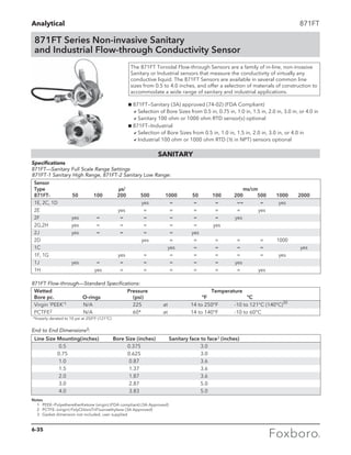
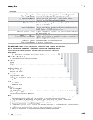
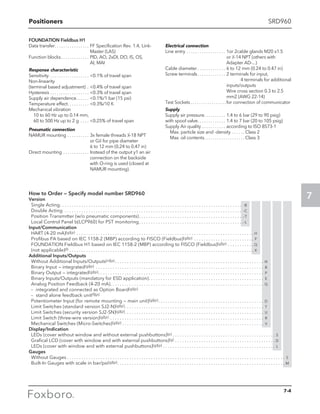
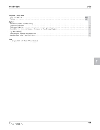
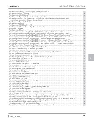
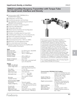
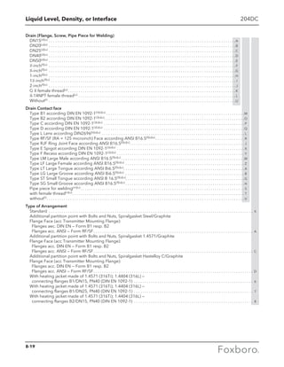
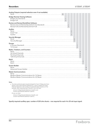
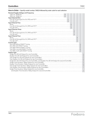
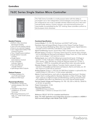
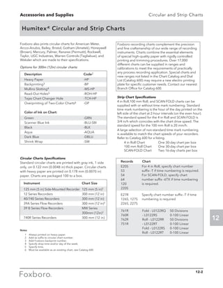
![Flow (Vortex Flowmeters) 84
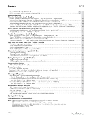
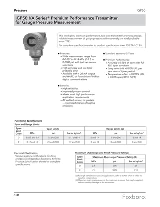
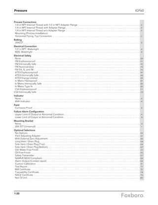
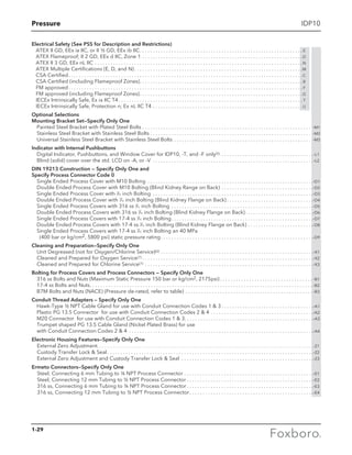
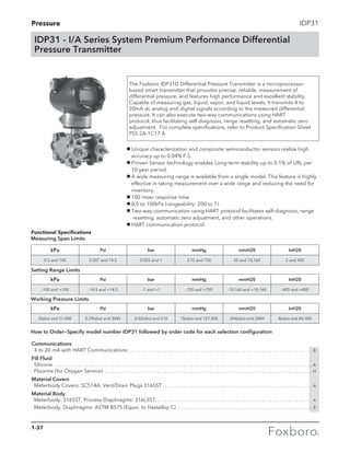
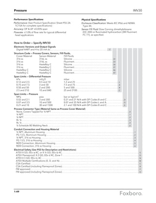
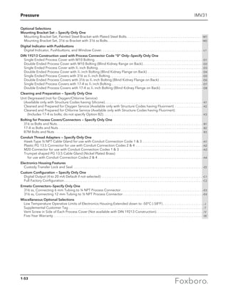
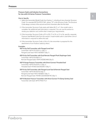
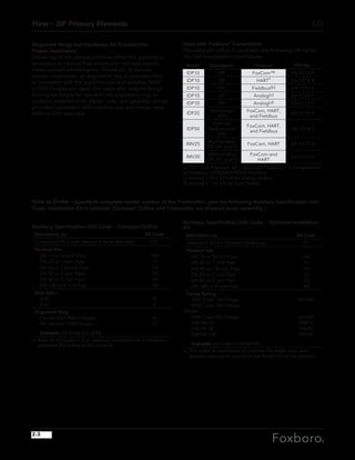
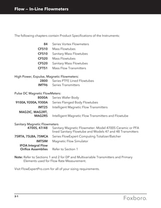
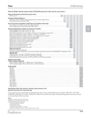
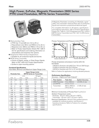
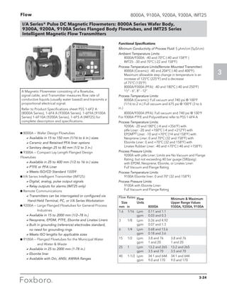
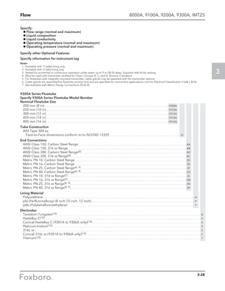
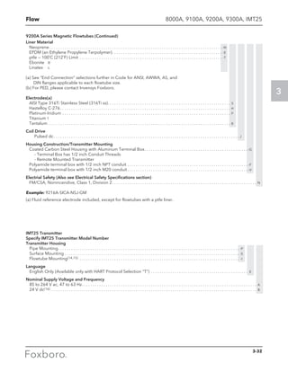
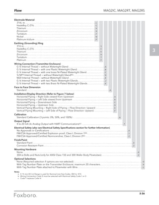
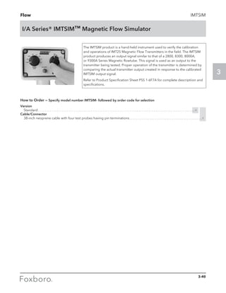
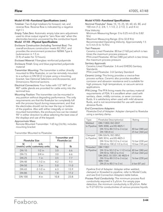
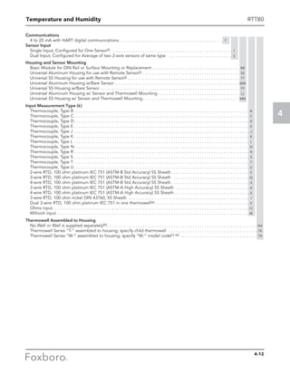
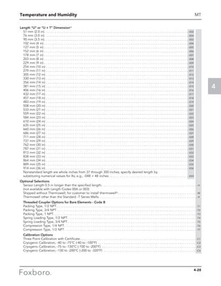
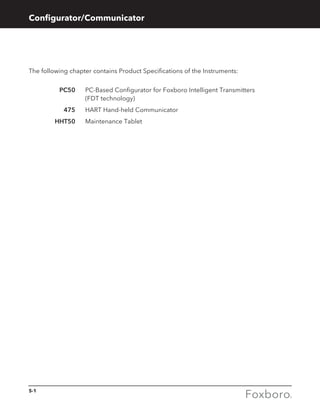
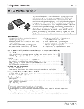
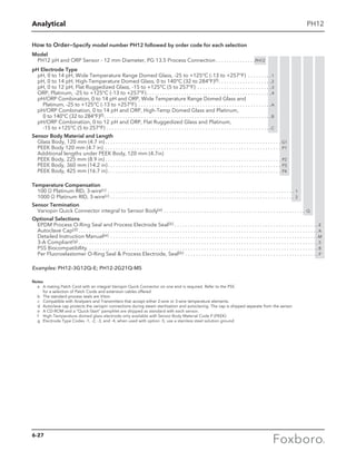
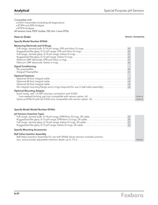
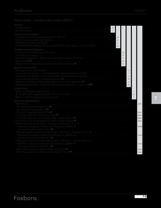
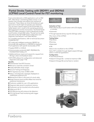
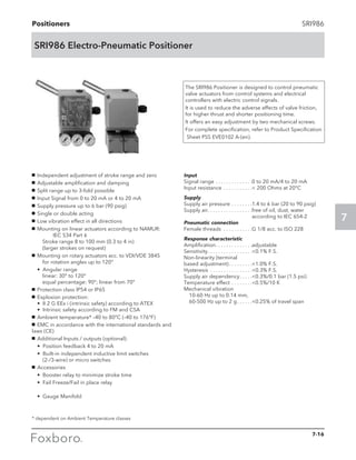
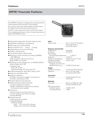
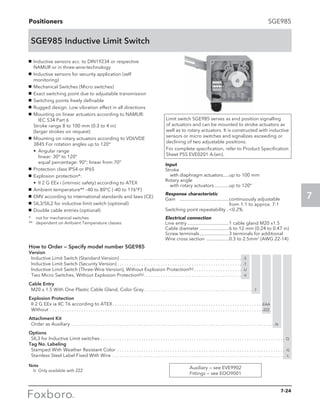
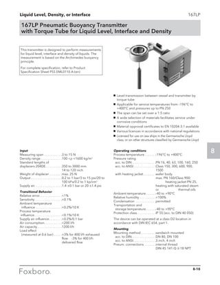
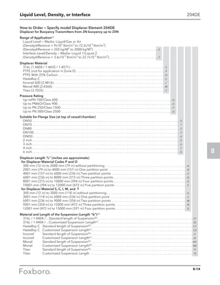
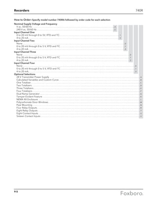
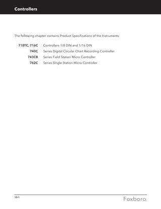
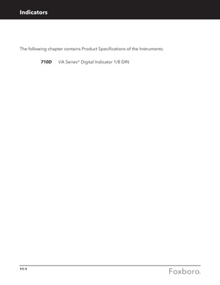
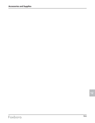
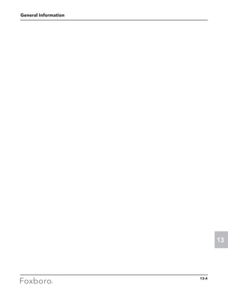
84S: Sanitary Vortex Flowmeter
How to Order—Specify model number 84S followed by order code for each selection
Electronics Type
Intelligent Electronics, HART Communication Protocol,
with Pulse Output . . . . . . . . . . . . . . . . . . . . . . . . . . . . . . . . . . . . . . . . . . . . . . . -T
Intelligent Electronics, HART Communication Protocol,
without Pulse Output . . . . . . . . . . . . . . . . . . . . . . . . . . . . . . . . . . . . . . . . . . . . -U
Intelligent Electronics, Low Power, HART Protocol, with Pulse Output(c) . . . . . -L
Intelligent Electronics, Low Power, HART Protocol, without Pulse Output(c) . -M
Nominal Line Size
2 in (DN 50), Stainless Steel Tubing . . . . . . . . . . . . . . . . . . . . . . . . . . . . . . . . . . . . . . 02
3 in (DN 80), Stainless Steel Tubing . . . . . . . . . . . . . . . . . . . . . . . . . . . . . . . . . . . . . . 03
End Connection Type (Welded to Flowmeter Body) (a)
3A I-Line Fitting, Mates with Cherry Burrell 15 WI or Equivalent . . . . . . . . . . . . . . . . . C
ANSI Class 150 RF Flange (b) . . . . . . . . . . . . . . . . . . . . . . . . . . . . . . . . . . . . . . . . . . . . . . . F
Metric (DIN 11851) Coupling with External Knuckle Thread, per DIN 405, Part 1 . . . M
RJT Coupling per BS 1864, with External Whitworth Thread, 6 TPI . . . . . . . . . . . . . . . R
3A Tri-Clamp Type Quick-Disconnect Ferrule, Mates
with Tri-Clover 14 WMP, or equivalent . . . . . . . . . . . . . . . . . . . . . . . . . . . . . . . . . . . . . . T
ISS (ISO 2853) Coupling with External Trapezoidal Thread, 8 TPI . . . . . . . . . . . . . . . . U
Local Digital Indicator/Configurator
No Digital Indicator/Configurator (Blind Unit) . . . . . . . . . . . . . . . . . . . . . . . . . . . . . . . . . . . . . . N
Full Function Digital Indicator/Configurator . . . . . . . . . . . . . . . . . . . . . . . . . . . . . . . . . . . . . . . . J
Electronics Housing Material and Conduit Connections
Remote Mounted; Aluminum Housing; 1/2 NPT Conduit Connections . . . . . . . . . . . . . . . . . . . . R
Remote Mounted; Aluminum Housing; M20 Conduit Connections . . . . . . . . . . . . . . . . . . . . . . . . W
Electrical Safety (Also see Electrical Safety Specifications section)
ATEX intrinsically Safe; II 1 GD, EEx ia IIC; T4; with Housing Code W only. . . . . . . . . . . . . . . . . . . . . . . E
ATEX flameproof; for II 2 (1) GD, EEx d [ia] IIC; T4; with Housing Code W only. . . . . . . . . . . . . . . . . . H
CSA intrinsically safe; Division 1 / Zone 0; T4. . . . . . . . . . . . . . . . . . . . . . . . . . . . . . . . . . . . . . . . . . . . . . . . C
CSA nonincendive; Division 2; T4 . . . . . . . . . . . . . . . . . . . . . . . . . . . . . . . . . . . . . . . . . . . . . . . . . . . . . . . . . M
CSA explosionproof; Division 1 / Zone 0; T5. . . . . . . . . . . . . . . . . . . . . . . . . . . . . . . . . . . . . . . . . . . . . . . . . D
FM intrinsically safe for Ex ia Class I, Division 1 Groups A,B,C and D, Class II and III, Division 2
Groups E, F and G, T4 @ 80°C. Dust-ignitionproof for Class II and III, Division 1, Groups C and D . . . . F
FM nonincendive Class I, II and III, Division 2, Groups A,B,C,D,F and G, T4 @ 80°C . . . . . . . . . . . . . . K
FM explosionproof for Class I, Division 1, Groups B,C and D, T6 @ 80°C . . . . . . . . . . . . . . . . . . . . . . . G
IECEx intrinsically safe; Ex ia IIC; T4; Dust-ignitionproof Ex tD A20, IP66 with . . . . . . . . . . . . . . . . . . . . L
Mounting Code W only.
IECEx flameproof; Ex d [ia] IIC; T4; Dust-ignitionproof Ex tD A20, IP66 with . . . . . . . . . . . . . . . . . . . . . B
Mounting Code W only.
NEPSI Intrinsically Safe, Zone 0, Ex ia II C, T4 (-20C to 80C or -40C to 80C w/o display) . . . . . . . . . . . R
NEPSI Flameproof, Zone 1, Ex d II C, T5 (except acetylene) (-20C to 85C or -40C to 85C w/o display) . . . . S
No Agency Electrical Certifications; (with CE mark, and PED Controls and Records). . . . . . . . . . . . . . Y
No Agency Certifications; (no CE mark; Units not to be installed in European Union . . . . . . . . . . . . . Z
(EU) countries).
Optional Selections
Foxboro Certificates of Compliance/Conformance
Standard Certificate of Compliance . . . . . . . . . . . . . . . . . . . . . . . . . . . . . . . . . . . . . . . . . . . . . . . . . . . . . . . . . . . . -L
Material Certification of Process Wetted Metal (Conforms to BS EN 10204 3.1) . . . . . . . . . . . . . . . . . . . . . . -M
Foxboro Calibration Certificate
Calibration and Pressure Test Certification . . . . . . . . . . . . . . . . . . . . . . . . . . . . . . . . . . . . . . . . . . . . . . . . . . . . . -N
Instruction Manual
Detailed Instruction Manual in place of Universal MI 019-145 . . . . . . . . . . . . . . . . . . . . . . . . . . . . . . . . . . . . . -C
Notes
(a) Mating end connections, gaskets, and clamps to be supplied by the user.
(b) WirelessHART Adaptors, Temperature Converters and Gateways can be ordered separately via part numbers 217233, 217234, 211735, 220390,
211734, 219035 and 211749 .
(c) Models 11, 13, 15: CERT-K only available with MR-01. Models 40, 43, 45: CERT-K limited to PB-AM, PB-BM, DE-A with MR-01, or DE-B with MR-01.
3-7](https://image.slidesharecdn.com/catalogfoxboromeasuremeandinstruments01-13-150912171749-lva1-app6891/85/Foxboro-Measurement-and-Control-Instruments-92-320.jpg)
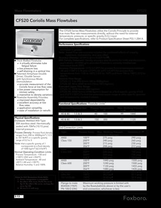
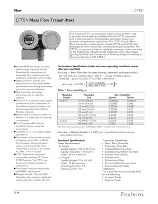
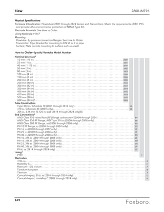
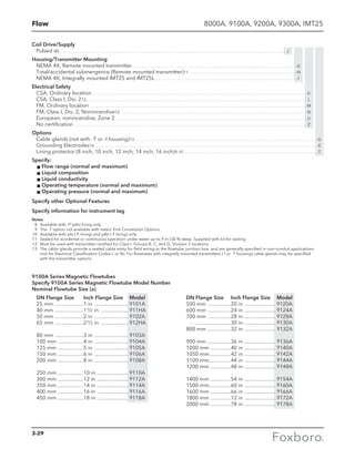
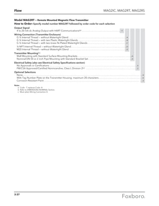
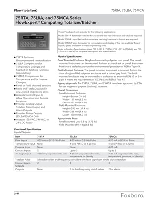
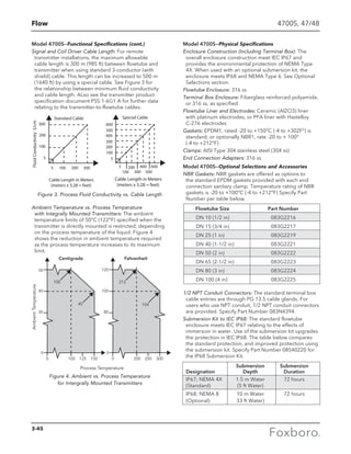
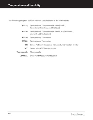
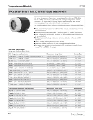
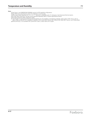

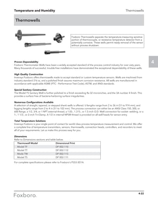
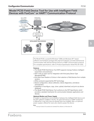
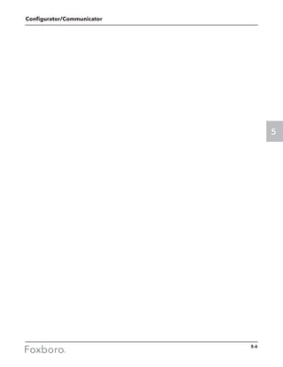
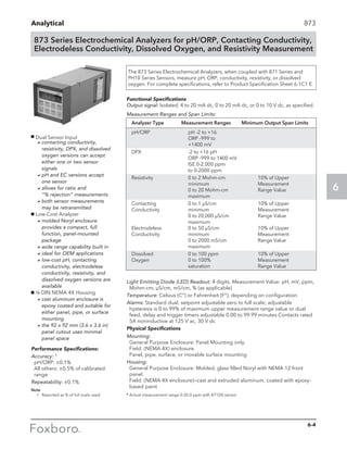
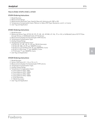
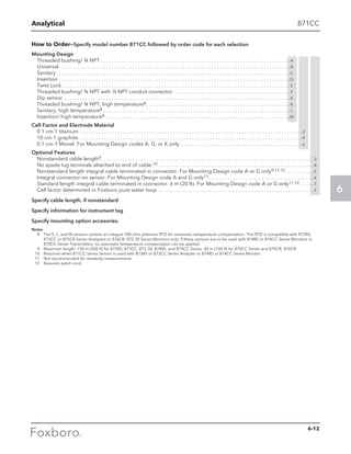
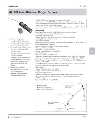
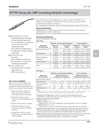
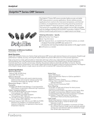
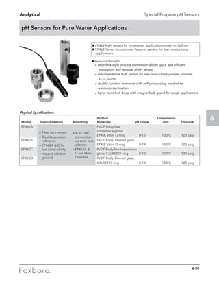
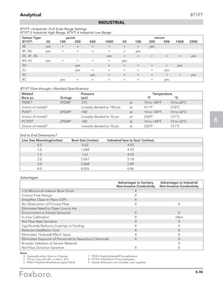
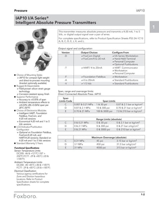
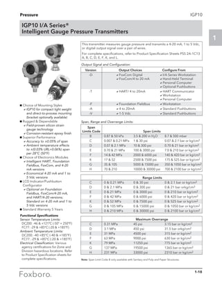
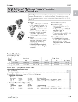
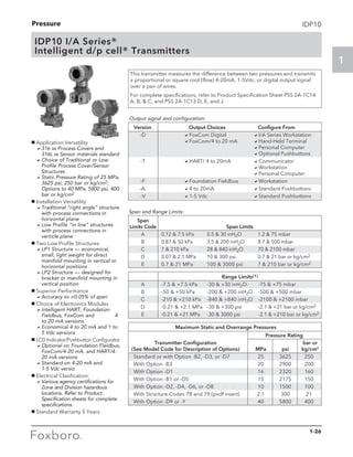
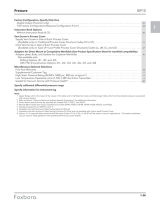
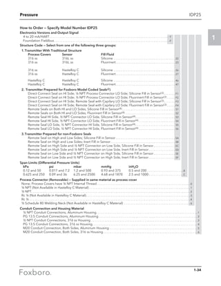
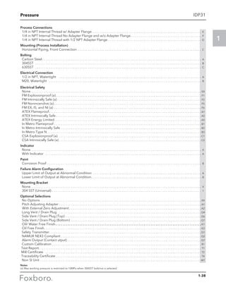
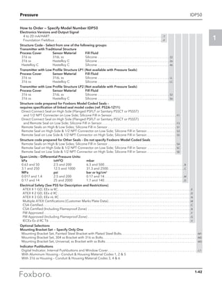
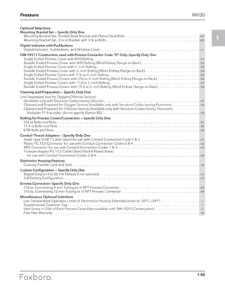
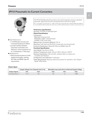
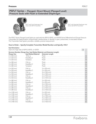
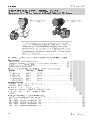
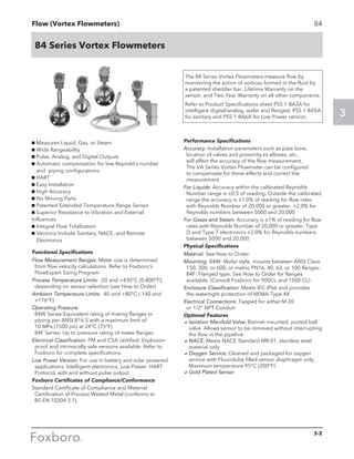
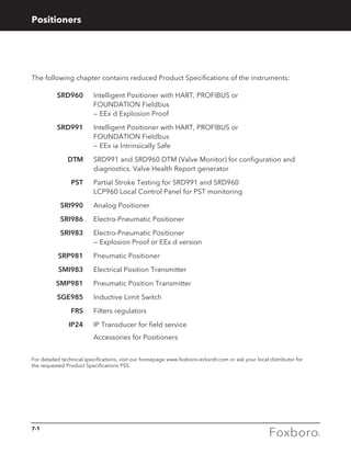
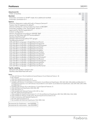
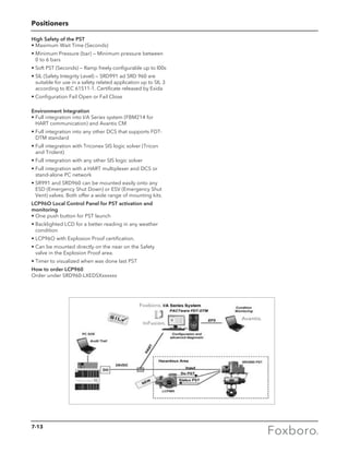
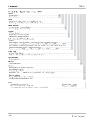
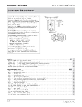
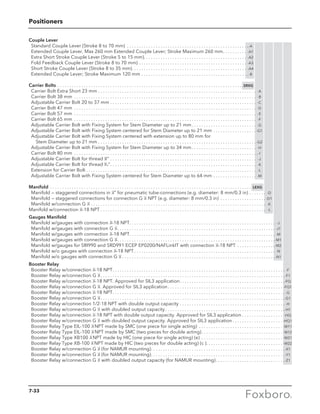
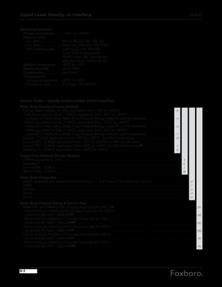
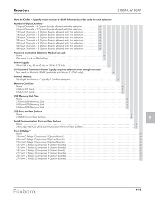
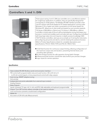
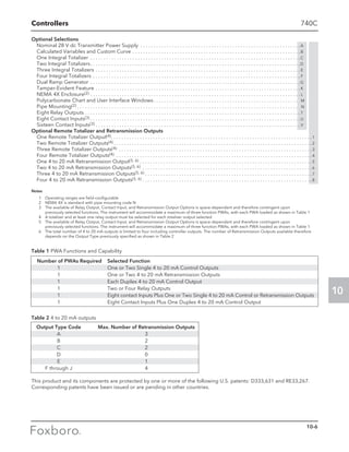
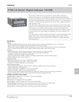
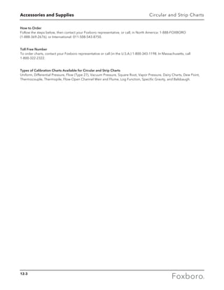
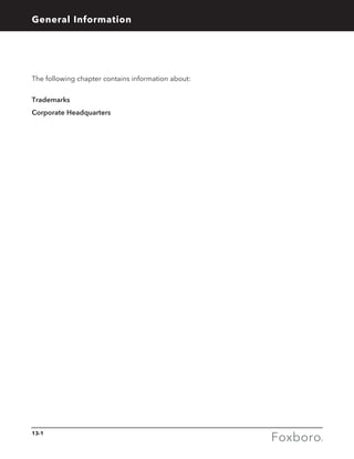
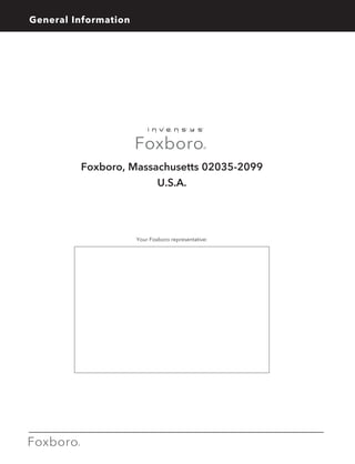
![Analytical 871FT
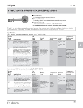
How to Order—Specify model number 871FT followed by order code for each selection
Flow-through Conductivity Sensor: Use with 875EC Intelligent Analyzer, or 876EC Series Intelligent Transmitter, or
873EC or 873AEC Series Analyzers
Sensor Type
Sanitary, High Range Conductivity . . . . . . . . . . . . . . . . . . . . . . . . . . . . . . . . . . . . . . . -1
Sanitary, Low Range Conductivity . . . . . . . . . . . . . . . . . . . . . . . . . . . . . . . . . . . . . . . . -2
Industrial, High Range Conductivity . . . . . . . . . . . . . . . . . . . . . . . . . . . . . . . . . . . . . . -3
Industrial, Low Range Conductivity . . . . . . . . . . . . . . . . . . . . . . . . . . . . . . . . . . . . . . -4
Nominal Line Size
English (USA)
½ in . . . . . . . . . . . . . . . . . . . . . . . . . . . . . . . . . . . . . . . . . . . . . . . . . . . . . . . . . . . . . . . . . . . . . C
¾ in Sanitary only . . . . . . . . . . . . . . . . . . . . . . . . . . . . . . . . . . . . . . . . . . . . . . . . . . . . . . . . . . D
1.0 in . . . . . . . . . . . . . . . . . . . . . . . . . . . . . . . . . . . . . . . . . . . . . . . . . . . . . . . . . . . . . . . . . . . . E
1.5 in . . . . . . . . . . . . . . . . . . . . . . . . . . . . . . . . . . . . . . . . . . . . . . . . . . . . . . . . . . . . . . . . . . . . . F
2.0 in . . . . . . . . . . . . . . . . . . . . . . . . . . . . . . . . . . . . . . . . . . . . . . . . . . . . . . . . . . . . . . . . . . . . G
3.0 in15 . . . . . . . . . . . . . . . . . . . . . . . . . . . . . . . . . . . . . . . . . . . . . . . . . . . . . . . . . . . . . . . . . . . H
4.0 in15 . . . . . . . . . . . . . . . . . . . . . . . . . . . . . . . . . . . . . . . . . . . . . . . . . . . . . . . . . . . . . . . . . . . J
End Connection Material
None (One-piece Insulator—Sanitary)24 . . . . . . . . . . . . . . . . . . . . . . . . . . . . . . . . . . . . . . . . . . . . -1
Hastelloy C-276 14 . . . . . . . . . . . . . . . . . . . . . . . . . . . . . . . . . . . . . . . . . . . . . . . . . . . . . . . . . . . . . . -2
316 ss14 . . . . . . . . . . . . . . . . . . . . . . . . . . . . . . . . . . . . . . . . . . . . . . . . . . . . . . . . . . . . . . . . . . . . . . . -3
Carp 20—CB3 14,16 . . . . . . . . . . . . . . . . . . . . . . . . . . . . . . . . . . . . . . . . . . . . . . . . . . . . . . . . . . . . . . -4
90 Cu/10 Ni (per UNS C70600)14,30 . . . . . . . . . . . . . . . . . . . . . . . . . . . . . . . . . . . . . . . . . . . . . . . -9
Insulator Material
Virgin ‘PEEK’ (Sanitary)13,17 . . . . . . . . . . . . . . . . . . . . . . . . . . . . . . . . . . . . . . . . . . . . . . . . . . . . . . . . . . A
PVDF14,18 . . . . . . . . . . . . . . . . . . . . . . . . . . . . . . . . . . . . . . . . . . . . . . . . . . . . . . . . . . . . . . . . . . . . . . . . . . B
PCTFE18,19 . . . . . . . . . . . . . . . . . . . . . . . . . . . . . . . . . . . . . . . . . . . . . . . . . . . . . . . . . . . . . . . . . . . . . . . . . C
Glass-filled ‘PEEK’6,14 . . . . . . . . . . . . . . . . . . . . . . . . . . . . . . . . . . . . . . . . . . . . . . . . . . . . . . . . . . . . . . . D
End Connection Form
Tri-Clamp24 . . . . . . . . . . . . . . . . . . . . . . . . . . . . . . . . . . . . . . . . . . . . . . . . . . . . . . . . . . . . . . . . . . . . . . . . . . . . -1
Pipe, NTP12,14,15 . . . . . . . . . . . . . . . . . . . . . . . . . . . . . . . . . . . . . . . . . . . . . . . . . . . . . . . . . . . . . . . . . . . . . . . . -2
Flange, ANSI Class 15014,20 . . . . . . . . . . . . . . . . . . . . . . . . . . . . . . . . . . . . . . . . . . . . . . . . . . . . . . . . . . . . . . -3
Flange, ANSI Class 30014,23 . . . . . . . . . . . . . . . . . . . . . . . . . . . . . . . . . . . . . . . . . . . . . . . . . . . . . . . . . . . . . . -4
Flange, Flat Face [end connection material selection ‘9’ only]14, 30 . . . . . . . . . . . . . . . . . . . . . . . . . . . . -7
RTD
None . . . . . . . . . . . . . . . . . . . . . . . . . . . . . . . . . . . . . . . . . . . . . . . . . . . . . . . . . . . . . . . . . . . . . . . . . . . . . . . . . . . . . . . C
1000 ohm RTD (for use with 870ITEC and 875EC) . . . . . . . . . . . . . . . . . . . . . . . . . . . . . . . . . . . . . . . . . . . . . . . R
100 ohm RTD . . . . . . . . . . . . . . . . . . . . . . . . . . . . . . . . . . . . . . . . . . . . . . . . . . . . . . . . . . . . . . . . . . . . . . . . . . . . . . . T
Cable Options
Cable length per Sales Order (100 ft maximum recommended length)31 . . . . . . . . . . . . . . . . . . . . . . . . . . . . . . . -3
Cable with Lugless Termination (e.g. use with 873 Analyzers) . . . . . . . . . . . . . . . . . . . . . . . . . . . . . . . . . . . . . . . . . -4
Shielded Teflon Cable26 . . . . . . . . . . . . . . . . . . . . . . . . . . . . . . . . . . . . . . . . . . . . . . . . . . . . . . . . . . . . . . . . . . . . . . . . . . -9
Low Smoke Cable30 . . . . . . . . . . . . . . . . . . . . . . . . . . . . . . . . . . . . . . . . . . . . . . . . . . . . . . . . . . . . . . . . . . . . . . . . . . . . . -N
Quick Disconnect, Patch cord cable connection29, 30 . . . . . . . . . . . . . . . . . . . . . . . . . . . . . . . . . . . . . . . . . . . . . . . . . -Q
O-Ring Options14
Perfluoroelastomer (Chemraz)21 . . . . . . . . . . . . . . . . . . . . . . . . . . . . . . . . . . . . . . . . . . . . . . . . . . . . . . . . . . . . . . . . . . . . . . . -P
Viton18,21 . . . . . . . . . . . . . . . . . . . . . . . . . . . . . . . . . . . . . . . . . . . . . . . . . . . . . . . . . . . . . . . . . . . . . . . . . . . . . . . . . . . . . . . . . . . -V
Calibration Cable
Calibration Cable22,27 . . . . . . . . . . . . . . . . . . . . . . . . . . . . . . . . . . . . . . . . . . . . . . . . . . . . . . . . . . . . . . . . . . . . . . . . . . . . . . . . . . . . . C-
6-37](https://image.slidesharecdn.com/catalogfoxboromeasuremeandinstruments01-13-150912171749-lva1-app6891/85/Foxboro-Measurement-and-Control-Instruments-200-320.jpg)
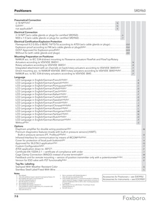
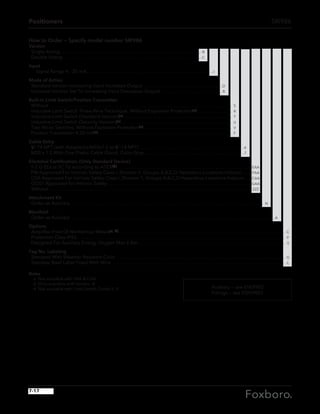
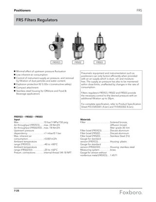
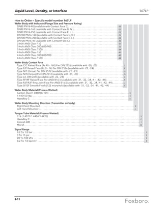
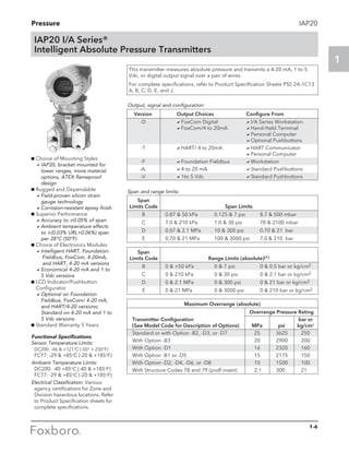
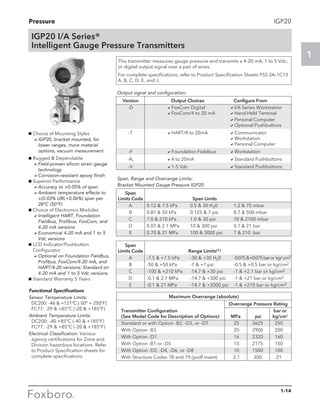
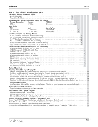
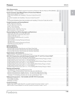
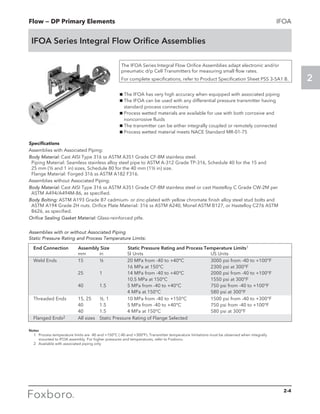
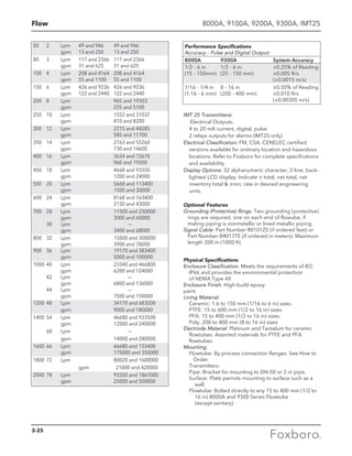
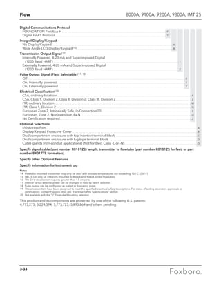
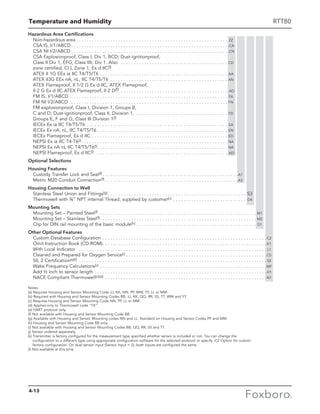
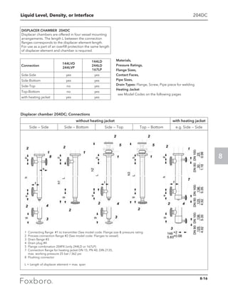
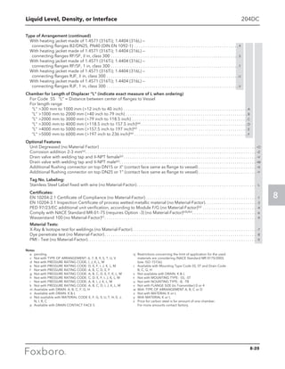
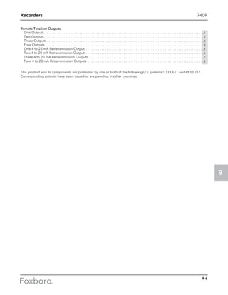
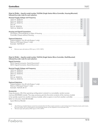
![Liquid Level, Density, or Interface 204DE
Optional Features
for application in Zone 0 (Additional grounding rope) (not available with Displacer Material: P). . . . . . . . . . . . . . . . . . . . . E
Damping Spring (Mat. 1.4301, Max. 250° C [482° F])(f). . . . . . . . . . . . . . . . . . . . . . . . . . . . . . . . . . . . . . . . . . . . . . . . . . . . . . . . . . -D
Damping Spring (Mat. HC, Max. 350° C [662° F])(f). . . . . . . . . . . . . . . . . . . . . . . . . . . . . . . . . . . . . . . . . . . . . . . . . . . . . . . . . . . . . -C
Degreased . . . . . . . . . . . . . . . . . . . . . . . . . . . . . . . . . . . . . . . . . . . . . . . . . . . . . . . . . . . . . . . . . . . . . . . . . . . . . . . . . . . . . . . . . . . . . . -O
Tag No. Labeling
Stainless Steel Label Fixed With Wire (Text required). . . . . . . . . . . . . . . . . . . . . . . . . . . . . . . . . . . . . . . . . . . . . . . . . . . . . . . . . . . -L
Certificates
EN 10204-2.1, Certificate Of Compliance. . . . . . . . . . . . . . . . . . . . . . . . . . . . . . . . . . . . . . . . . . . . . . . . . . . . . . . . . . . . . . . . . . . . . -1
EN 10204-3.1, Inspection Certificate Of Process Wetted Metallic Material
(not available with Displacer Material: P and 0). . . . . . . . . . . . . . . . . . . . . . . . . . . . . . . . . . . . . . . . . . . . . . . . . . . . . . . . . . . . . . . . -3
PMI — Test (not available with Displacer Material: P and 0). . . . . . . . . . . . . . . . . . . . . . . . . . . . . . . . . . . . . . . . . . . . . . . . . . . . . . -5
Tags
Length “b”: required for Material Suspension Length codes S2, C2, 12, M2, T2
Press. Rating Chamber: required for Material Suspension Length codes S2, C2,12, M2, T2
List = PN16; PN40; PN63; PN100; PN160; PN250; PN400; PN500; Cl.150; Cl.300; Cl.600; Cl.900; Cl.1500; Cl.2500
Length “L”: required
300 to 2000 mm or 11.81 to 78.74 in — for Displacer Length code A
2001 to 4000 mm or 78.78 to 157.48 in — for Displacer Length code B
4001 to 6000 mm or 157.52 to 236.22 in — for Displacer Length code C
6001 to 8000 mm or 236.26 to 314.96 in — for Displacer Length code D
8001 to 10000 mm or 315 to 393.70 in — for Displacer Length code E
10001 to 12000 mm or 393.74 to 472.44 in — for Displacer Length code F
300 to 3000 mm or 11.81 to 118.11 in — for Displacer Length code K
3001 to 6000 mm or 118.15 to 236.22 in — for Displacer Length code L
6001 to 9000 mm or 236.26 to 354.33 in — for Displacer Length code M
9001 to 12000 mm or 354.37 to 472.44 in — for Displacer Length code N
12001 to 15000 mm or 472.48 to 590.55 in — for Displacer Length code 0
Lower Density: required; select kg/m3 or lbm/in3
Upper Density: required; select kg/m3 or lbm/in3
Static Pressure (actual): required
-1 to 100 bar; -14.5 to 600 psig — for Pressure Rating code D
-1 to 160 bar; -14.5 to 900 psig — for Pressure Rating code E
-1 to 250 bar; -14.5 to 1200 psig — for Pressure Rating code F
-1 to 500 bar; -14.5 to 2500 psig — for Pressure Rating code G
Tag No. Labeling: required with Optional Feature codes -L and -S
Use with Transmitter: required List = 144LD; 144LVD; 244LD; 244LVP; 167LP
Notes
a Upper and Lower Medium Density required (at operating temperature)
b Only in connection with Modelcode 204DC
c Exact length required (Contact face of flange to upper end of displacer)
d All ±8mm (0.3inch)
e Pending
f Required for 244LD Option -G
8-15](https://image.slidesharecdn.com/catalogfoxboromeasuremeandinstruments01-13-150912171749-lva1-app6891/85/Foxboro-Measurement-and-Control-Instruments-252-320.jpg)


Invensys Operations Management provides specifications and ordering information for their instrumentation and accessories catalog, which includes various types of pressure transmitters and flow measurement devices. Customers can contact their Foxboro representative for assistance, guidance in specifying products, and placing orders. The document emphasizes the availability of technical data for different instruments and the procedures for proper ordering.


![[HES2014] HackRF A Low Cost Software Defined Radio Platform by Benjamin Vernoux](https://cdn.slidesharecdn.com/ss_thumbnails/day2-04-140412114412-phpapp02-thumbnail.jpg?width=640&height=640&fit=bounds)


![射頻電子 - [第三章] 史密斯圖與阻抗匹配](https://cdn.slidesharecdn.com/ss_thumbnails/ch3-150613065103-lva1-app6892-thumbnail.jpg?width=640&height=640&fit=bounds)


