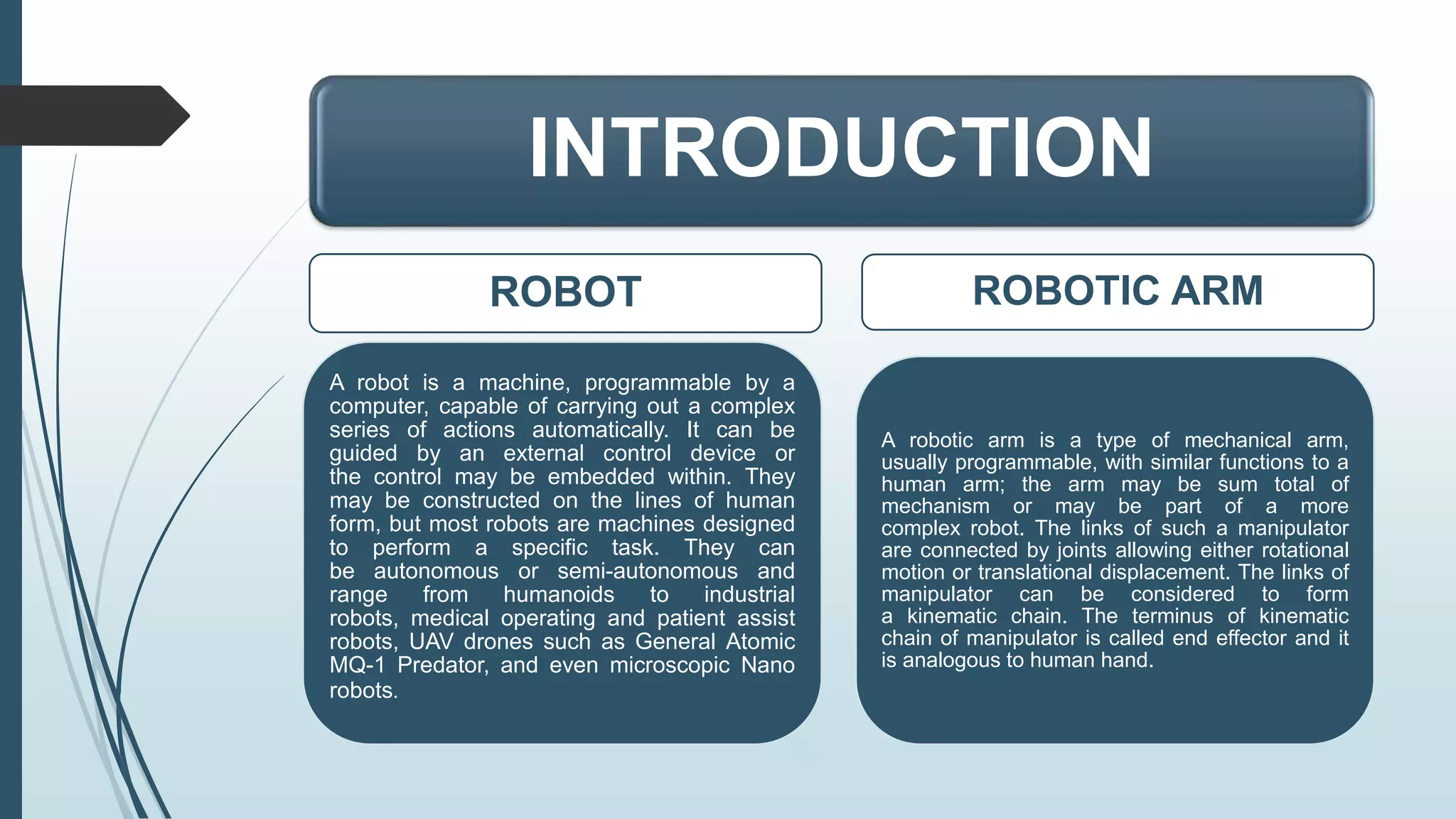
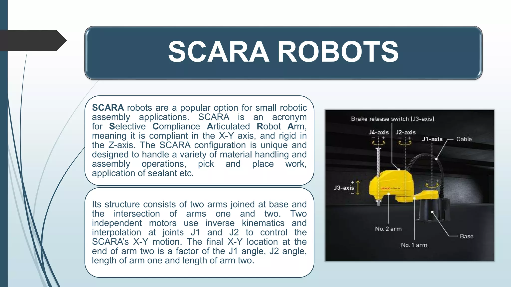
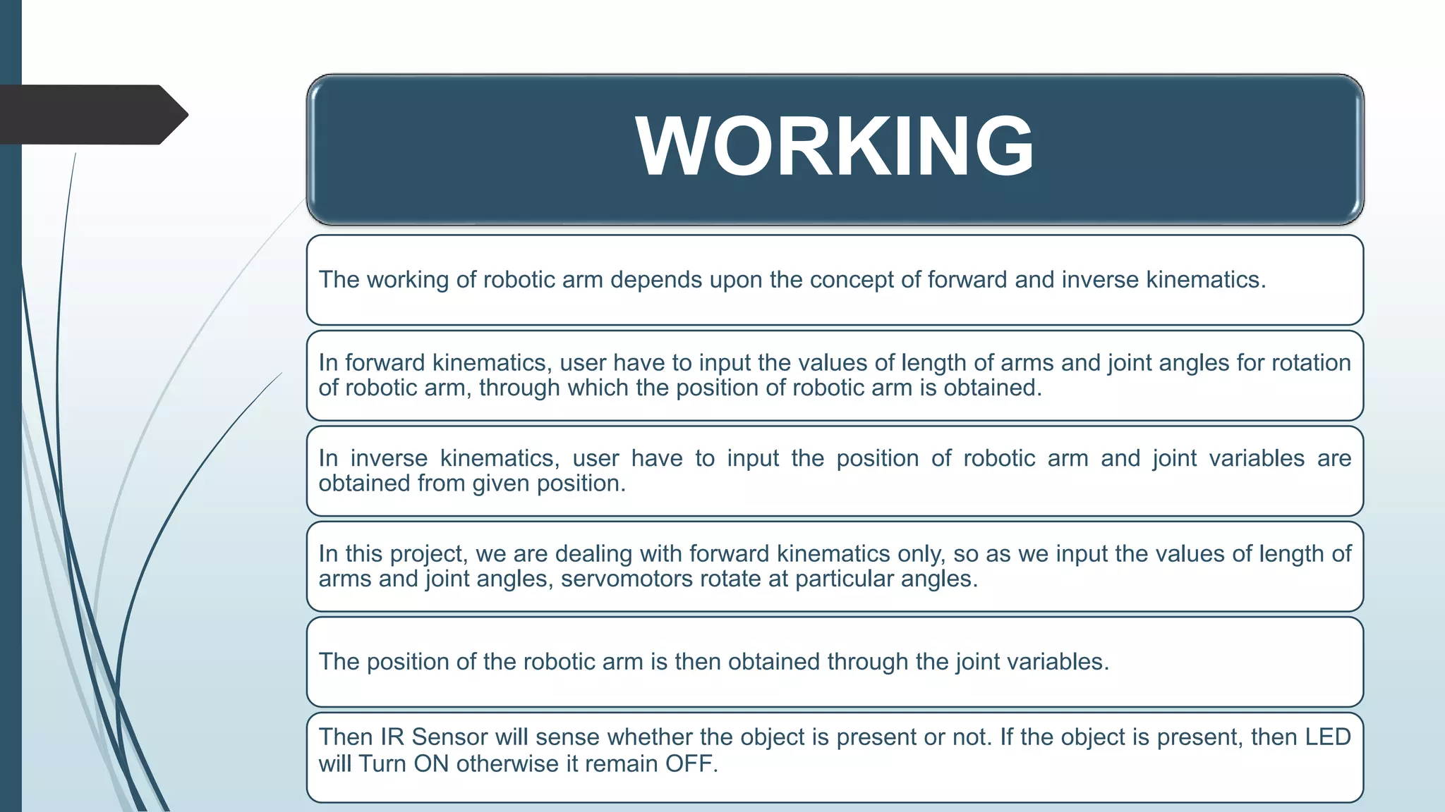
It is a PowerPoint presentation of the group project that I have made along with friends during my undergraduate degree. Hope it will be helpful for you.
Contents:
(1) Introduction
(2) Brief History
(3) Components
(4) Construction (Circuit Diagram)
(5) Working
(6) Arduino Code
(7) Future Scope
It was made with the help of the TinkerCAD platform. You may use this platform and run the given code in this PPT for a better understanding.
3. INTRODUCTION
ROBOT
A robot is a machine, programmable by a
computer, capable of carrying out a complex
series of actions automatically. It can be
guided by an external control device or
the control may be embedded within. They
may be constructed on the lines of human
form, but most robots are machines designed
to perform a specific task. They can
be autonomous or semi-autonomous and
range from humanoids to industrial
robots, medical operating and patient assist
robots, UAV drones such as General Atomic
MQ-1 Predator, and even microscopic Nano
robots.
ROBOTIC ARM
A robotic arm is a type of mechanical arm,
usually programmable, with similar functions to a
human arm; the arm may be sum total of
mechanism or may be part of a more
complex robot. The links of such a manipulator
are connected by joints allowing either rotational
motion or translational displacement. The links of
manipulator can be considered to form
a kinematic chain. The terminus of kinematic
chain of manipulator is called end effector and it
is analogous to human hand.
5. SCARA ROBOTS
SCARA robots are a popular option for small robotic
assembly applications. SCARA is an acronym
for Selective Compliance Articulated Robot Arm,
meaning it is compliant in the X-Y axis, and rigid in
the Z-axis. The SCARA configuration is unique and
designed to handle a variety of material handling and
assembly operations, pick and place work,
application of sealant etc.
Its structure consists of two arms joined at base and
the intersection of arms one and two. Two
independent motors use inverse kinematics and
interpolation at joints J1 and J2 to control the
SCARA’s X-Y motion. The final X-Y location at the
end of arm two is a factor of the J1 angle, J2 angle,
length of arm one and length of arm two.
6. BRIEF HISTORY
Early Conceptions of Robots
One of first instances of a mechanical device
built to regularly carry out a particular physical
task occurred around 3000 B.C. Egyptian water
clocks used human figurines to strike the hour
bells. In 400 B.C., Archytus of Taremtum,
inventor of pulley and screw, also invented a
wooden pigeon that could fly. In first century
A.D., Petronius Arbiter made a doll that could
move like a human being. Giovanni Torriani
created a wooden robot that could fetch the
Emperor's daily bread from store in 1557. The
19th century was also filled with new robotic
creations, such as a talking doll by Edison and a
steam-powered robot by Canadians.
The First Modern Robots
The earliest robots were created in the early 1950s
by George C. Devol, an inventor from Louisville,
Kentucky. He invented and patented a
reprogrammable manipulator called "Unimate". For
next decade, he attempted to sell his product in the
industry, but did not succeed. In late 1960s,
businessman/engineer Joseph Engleberger
acquired Devol's robot patent and was able to
modify it into an industrial robot and form a
company called Unimation to produce and market
the robots. For his efforts, he is known in industry
as "the Father of Robotics."
In 1958, at Stanford Research Institute, Charles
Rosen led a research team in developing a robot
called "Shakey." It was far more advanced than the
original Unimate, which was designed for
specialized, industrial applications.
8. ARDUINO
It contains a microcontroller which is able to be programmed to sense and
control objects in the physical world. By responding to sensors and inputs, it is
able to interact with a large array of outputs such as LEDs, motors and displays.
Because of it’s flexibility and low cost, it has become a very popular choice to
create interactive projects.
It was introduced back in 2005 in Italy by Massimo Banzi as a way for non-
engineers to have access to a low cost, simple tool for creating hardware
projects.
It is an open source programmable circuit board that can be integrated into a
wide variety of projects.
9. ARDUINO UNO
One of the most popular Arduino boards out there is Arduino Uno. It is
an open-source microcontroller board based on
Microchip ATmega328P microcontroller and developed by Arduino.cc.
The board is equipped with sets of digital and analog input/output (I/O) pins
that may be interfaced to various expansion boards and other circuits.
The board has 14 digital I/O pins, 6 analog I/O pins, and is programmable
with Arduino IDE (Integrated Development Environment), via a type B USB
cable. It can be powered by USB cable or by an external 9-volt battery.
The word “Uno" means "one" in Italian and was chosen to mark the initial
release of Arduino Software.
10. BREADBOARD
A breadboard is a rectangular plastic
board with a bunch of tiny holes in it.
These holes let you easily insert
electronic components to prototype
an electronic circuit, like this one
with a battery, switch, resistor, and
an LED.
Modern breadboards are made from
plastic, and come in all shapes,
sizes, and even different colors.
While larger and smaller sizes are
available, the most common sizes
you will probably see are "full-size,"
"half-size," and "mini" breadboards.
11. SERVOMOTOR
A servomotor is a rotary actuator or linear actuator that allows for precise
control of angular or linear position, velocity and acceleration. It consists
of a suitable motor coupled to a sensor for position feedback.
A servo motor is a DC motor integrated with a gear train, a shaft encoder,
and some control logic so that it is easier to use. They have a limited
rotation, typically 180°.
A servo motor has a 3-pin interface with power (typically 5 V), ground, and
a control input.
The control input is typically a 50 Hz pulse-width modulated signal.
The servo's control logic drives the shaft to a position determined by the
duty cycle of the control input.
The servo's shaft encoder is typically a rotary potentiometer that produces
a voltage dependent on the shaft position.
12. IR SENSOR
It has two main parts i.e. IR Transmitter and
IR Receiver. The work of IR transmitter is to
transmit the infrared waves, whereas the
work of IR receiver is to receive these
infrared waves. IR receiver constantly sends
digital data in form of 0 or 1 to Vout pin of
sensor.
If there is an object in front of IR sensor, the
transmitted IR waves from IR transmitter
reflects from that object and is received by IR
receiver. IR sensor gives 0 in this condition.
Whereas, if there is no object in front of
IR sensor, the transmitted IR waves from
IR transmitter is not received by IR receiver,
then IR sensor gives 1 in this condition.
13. JUMPING WIRES
Jumper wires are simply wires that
have connector pins at each end,
allowing them to be used to connect
two points to each other without
soldering. Jumper wires are typically
used with breadboards and other
prototyping tools in order to make it
easy to change a circuit as needed.
Though jumper wires come in a variety
of colors, the colors don’t actually
mean anything. This means that a red
jumper wire is technically the same as
a black one. But the colors can be
used to your advantage in order to
differentiate between types of
connections, such as ground or power.
16. WORKING
The working of robotic arm depends upon the concept of forward and inverse kinematics.
In forward kinematics, user have to input the values of length of arms and joint angles for rotation
of robotic arm, through which the position of robotic arm is obtained.
In inverse kinematics, user have to input the position of robotic arm and joint variables are
obtained from given position.
In this project, we are dealing with forward kinematics only, so as we input the values of length of
arms and joint angles, servomotors rotate at particular angles.
The position of the robotic arm is then obtained through the joint variables.
Then IR Sensor will sense whether the object is present or not. If the object is present, then LED
will Turn ON otherwise it remain OFF.
17. FORWARD KINEMATICS
The Forward kinematics of a robotic arm is determined a group of parameters called
Denavit-Hartenberg (DH) parameters which used for deriving the homogenous
transformation matrices between the different frames assigned on robot arm structure.
The position coordinates of manipulator end-effector is given by:
𝑃𝑥 = 𝐿1 cos 𝜃1 + 𝐿2 cos(𝜃1 + 𝜃2 )
𝑃𝑦 = 𝐿1 sin 𝜃1 + 𝐿2 sin(𝜃1 + 𝜃2 )
18. FUTURE SCOPE
The work carried out in this project emphasized on
the simulation aspect only. Although the simulation
studies on digital computer produced good result,
the hardware implementation on a real direct drive
robot arm is the way to proceed this project.
Through experimental studies, the performance of
this controller under real practical environment can
be investigated.