Download to read offline
![Proline Promag 10W
Endress+Hauser 9
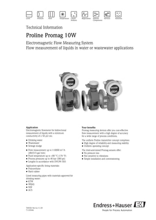
Performance characteristics
Reference operating
conditions
As per DIN EN 29104 and VDI/VDE 2641:
• Fluid temperature: +28 °C ± 2 K (+82 °F ± 2 K)
• Ambient temperature: +22 °C ±2 K (+72 °F ± 2 K)
• Warm-up period: 30 minutes
Installation conditions:
• Inlet run > 10 × DN
• Outlet run > 5 × DN
• Sensor and transmitter grounded.
• The sensor is centered in the pipe.
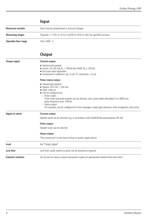
Maximum measured error • Current output: also typically ± 5 μA
• Pulse output: ±0.5% o.r. ± 2 mm/s (±0.5% o.r. ± 0.08 in/s) (o.r. = of reading)
Fluctuations in the supply voltage do not have any effect within the specified range.
A0003200
Max. measured error in % of reading
Repeatability Max. ±0.2% o.r. ± 2 mm/s (±0.2% o.r. ± 0.08 in/s) (o.r. = of reading)
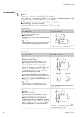
When using the measuring device in a:
• Pipe with a cathodic protection unit
The device is installed potential-free in the pipe.
Only the two flanges of the pipe are connected with a ground
cable (copper wire, at least 6 mm² / 0.0093 in²). Here, the
ground cable is mounted directly on the conductive flange
coating with flange screws.
Note the following when installing:
• The applicable regulations regarding potential-free installation
must be observed.
• There should be no electrically conductive connection
between the pipe and the device.
• The mounting material must withstand the applicable
torques.
A0010834
Potential equalization and cathodic protection
1 Power supply isolation transformer
2 Electrically isolated
Operating conditions Potential equalization
1
2 2
2.5
[%]
2.0
1.5
1.0
0.5
0
0.5 %
0 1 2 4 6 8 10 [m/s]
v
5 10 15 20 25 30 32 [ft]
0](https://image.slidesharecdn.com/prolinepromag10w-endresshauserdatasheet-electromagneticflowmeter-210818172518/85/Proline-promag-10-w-endress-hauser-datasheet-electromagnetic-flowmeter-9-320.jpg)
![Proline Promag 10W
14 Endress+Hauser
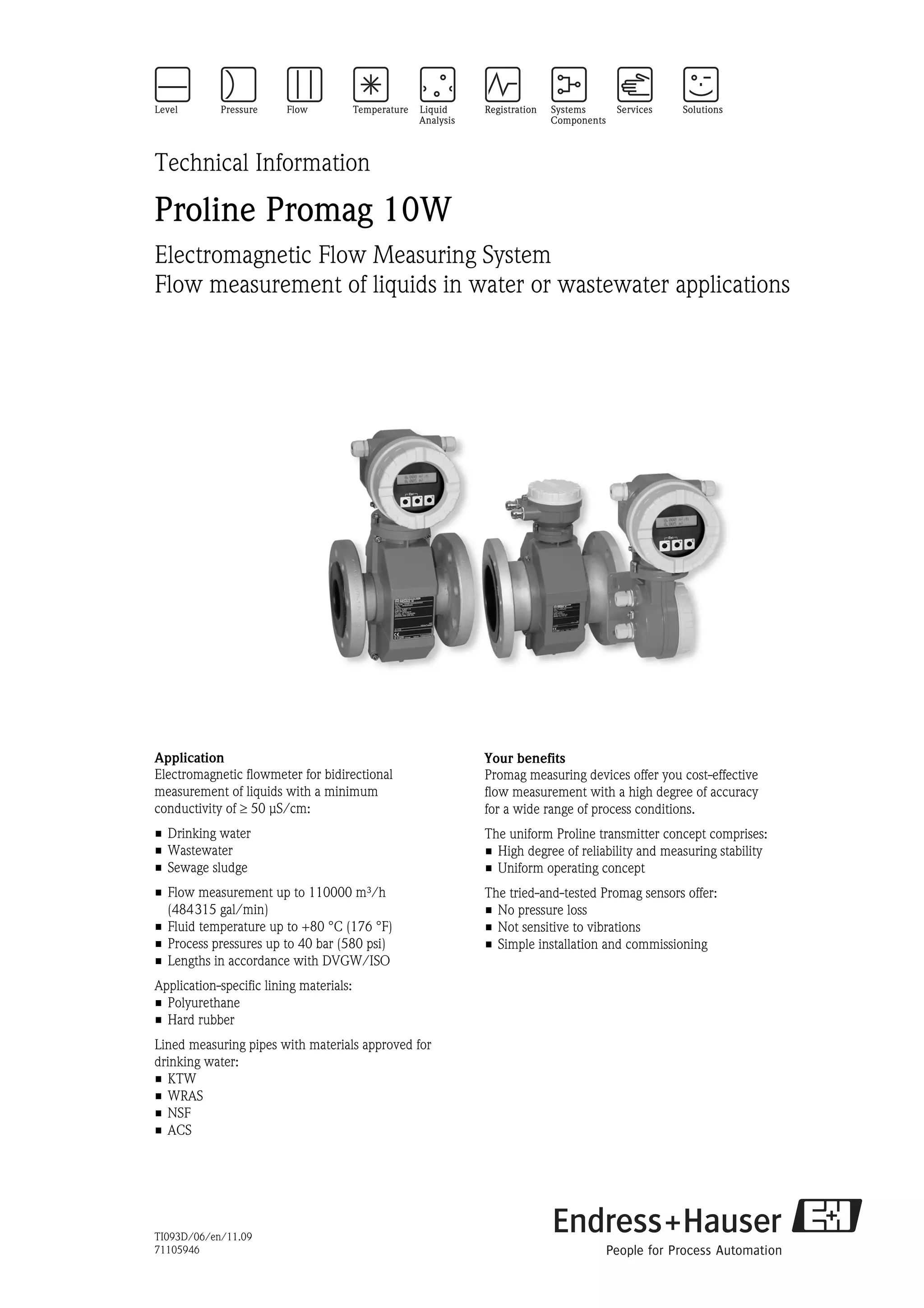
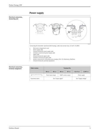
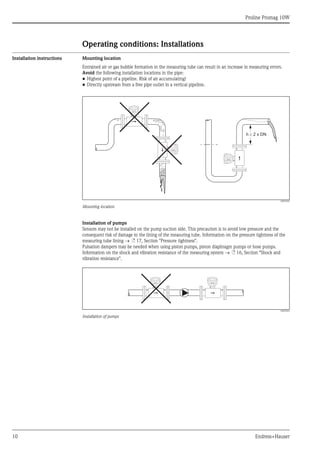
Adapters Suitable adapters to DIN EN 545 (double-flange reducers) can be used to install the sensor in larger-diameter
pipes. The resultant increase in the rate of flow improves measuring accuracy with very slow-moving fluids.
The nomogram shown here can be used to calculate the pressure loss caused by reducers and expanders.
! Note!
The nomogram only applies to liquids of viscosity similar to water.
1. Calculate the ratio of the diameters d/D.
2. From the nomogram read off the pressure loss as a function of flow velocity (downstream from the
reduction) and the d/D ratio.
A0003213
Pressure loss due to adapters
100
10
0.5
d / D
[mbar]
0.6 0.7 0.8 0.9
1 m/s
2 m/s
3 m/s
4 m/s
5 m/s
6 m/s
7 m/s
8 m/s
1
D
d
max. 8°](https://image.slidesharecdn.com/prolinepromag10w-endresshauserdatasheet-electromagneticflowmeter-210818172518/85/Proline-promag-10-w-endress-hauser-datasheet-electromagnetic-flowmeter-14-320.jpg)
![Proline Promag 10W
Endress+Hauser 15
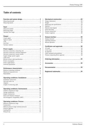
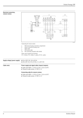
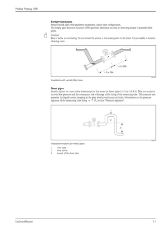
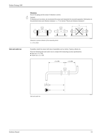
Length of connecting cable When mounting the remote version, please note the following to achieve correct measuring results:
• Fix cable run or lay in armored conduit. Cable movements can falsify the measuring signal especially in the
case of low fluid conductivities.
• Route the cable well clear of electrical machines and switching elements.
• If necessary, ensure potential equalization between sensor and transmitter.
• The permitted cable length Lmax is determined by the fluid conductivity.
A minimum conductivity of 50 μS/cm is needed for all fluids.
• When the empty pipe detection function is switched on (EPD),
the maximum connecting cable length is 10 m (33 ft).
A0003214
Permitted length of connecting cable for remote version
Area marked in gray = permitted range; Lmax = length of connecting cable in [m] ([ft]); fluid conductivity in [μS/cm]
L max
[ft]
200 600
0 400
200
100
50 100 200
[m]
[μS/cm]
L max
50](https://image.slidesharecdn.com/prolinepromag10w-endresshauserdatasheet-electromagneticflowmeter-210818172518/85/Proline-promag-10-w-endress-hauser-datasheet-electromagnetic-flowmeter-15-320.jpg)
![Proline Promag 10W
Endress+Hauser 17
Operating conditions: Process
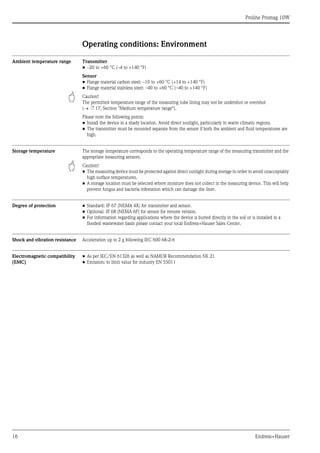
Medium temperature range The permitted temperature depends on the measuring tube lining:
• Polyurethane: –20 to +50 °C (-4 to +122 °F) (DN 25 to 1200 / 1 to 48")
• Hard rubber: 0 to +80 °C (+32 to +176 °F) (DN 50 to 2000 / 2 to 78")
Conductivity The minimum conductivity is: ≥ 50 μS/cm
! Note!
In the remote version, the necessary minimum conductivity also depends on the cable length
(→ ä 15, Section "Length of connecting cable").
Medium pressure range
(nominal pressure)
• EN 1092-1 (DIN 2501)
– PN 6 (DN 350 to 2000 / 14 to 78")
– PN 10 (DN 200 to 2000 / 8 to 78")
– PN 16 (DN 65 to 2000 / 3 to 78")
– PN 25 (DN 200 to 1000 / 8 to 40")
– PN 40 (DN 25 to 150 / 1 to 6")
• ANSI B 16.5
– Class 150 (DN 25 to 600 / 1 to 24")
– Class 300 (DN 25 to 150 / 1 to 6")
• AWWA
– Class D (DN 700 to 2000 / 28 to 78")
• JIS B2220
– 10 K (DN 50 to 300 / 2 to 12")
– 20 K (DN 25 to 300 / 1 to 12")
• AS 2129
– Table E (DN 80, 100, 150 to 1200 / 3", 4", 6 to 48")
• AS 4087
– PN 16 (DN 80, 100, 150 to 1200 / 3", 4", 6 to 48")
Pressure tightness Measuring tube lining: Polyurethane
Measuring tube lining: Hard rubber
Nominal diameter Limit values for abs. pressure [mbar] ([psi]) at fluid temperatures:
25 °C (77 °F) 50 °C (122 °F)
[mm] [inch] [mbar] [psi] [mbar] [psi]
25 to 1200 1 to 48" 0 0 0 0
Nominal diameter Limit values for abs. pressure [mbar] ([psi]) at fluid temperatures:
25 °C (77 °F) 70 °C (158 °F) 80 °C (176 °F)
[mm] [inch] [mbar] [psi] [mbar] [psi] [mbar] [psi]
50 to 2000 2 to 78" 0 0 0 0 0 0](https://image.slidesharecdn.com/prolinepromag10w-endresshauserdatasheet-electromagneticflowmeter-210818172518/85/Proline-promag-10-w-endress-hauser-datasheet-electromagnetic-flowmeter-17-320.jpg)
![Proline Promag 10W
18 Endress+Hauser
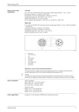
Limiting flow The diameter of the pipe and the flow rate determine the nominal diameter of the sensor.
The optimum flow velocity is between 2 to 3 m/s (6.5 to 9.8 ft/s). The velocity of flow (v), moreover, has to
be matched to the physical properties of the fluid:
• v < 2 m/s (6.5 ft/s): for abrasive fluids such as potter's clay, lime milk, ore slurry etc.
• v > 2 m/s (6.5 ft/s): for fluids causing build-up such as wastewater sludges etc.
Flow characteristic values (SI units)
Diameter Recommended flow Factory settings
[mm] [inch]
Min./max. full scale value
(v ~ 0.3 or 10 m/s)
Full scale value
Current output
(v ~ 2.5 m/s)
Pulse value
(~ 2 pulses/s)
Low flow
(v ~ 0.04 m/s)
25 1" 9 to 300 dm3
/min 75 dm3
/min 0.50 dm3
1 dm3
/min
32 – 15 to 500 dm3
/min 125 dm3
/min 1.00 dm3
2 dm3
/min
40 1½" 25 to 700 dm3/min 200 dm3/min 1.50 dm3 3 dm3/min
50 2" 35 to 1100 dm3
/min 300 dm3
/min 2.50 dm3
5 dm3
/min
65 – 60 to 2000 dm3
/min 500 dm3
/min 5.00 dm3
8 dm3
/min
80 3" 90 to 3000 dm3/min 750 dm3/min 5.00 dm3 12 dm3/min
100 4" 145 to 4700 dm3
/min 1200 dm3
/min 10.00 dm3
20 dm3
/min
125 – 220 to 7500 dm3
/min 1850 dm3
/min 15.00 dm3
30 dm3
/min
150 6" 20 to 600 m3/h 150 m3/h 0.025 m3 2.5 m3/h
200 8" 35 to 1100 m3
/h 300 m3
/h 0.05 m3
5.0 m3
/h
250 10" 55 to 1700 m3
/h 500 m3
/h 0.05 m3
7.5 m3
/h
300 12" 80 to 2400 m3/h 750 m3/h 0.10 m3 10 m3/h
350 14" 110 to 3300 m3
/h 1000 m3
/h 0.10 m3
15 m3
/h
375 15" 140 to 4200 m3
/h 1200 m3
/h 0.15 m3
20 m3
/h
400 16" 140 to 4200 m3/h 1200 m3/h 0.15 m3 20 m3/h
450 18" 180 to 5400 m3
/h 1500 m3
/h 0.25 m3
25 m3
/h
500 20" 220 to 6600 m3
/h 2000 m3
/h 0.25 m3
30 m3
/h
600 24" 310 to 9600 m3/h 2500 m3/h 0.30 m3 40 m3/h
700 28" 420 to 13500 m3
/h 3500 m3
/h 0.50 m3
50 m3
/h
– 30" 480 to 15000 m3
/h 4000 m3
/h 0.50 m3
60 m3
/h
800 32" 550 to 18000 m3/h 4500 m3/h 0.75 m3 75 m3/h
900 36" 690 to 22500 m3
/h 6000 m3
/h 0.75 m3
100 m3
/h
1000 40" 850 to 28000 m3
/h 7000 m3
/h 1.00 m3
125 m3
/h
– 42" 950 to 30000 m3/h 8000 m3/h 1.00 m3 125 m3/h
1200 48" 1250 to 40000 m3
/h 10000 m3
/h 1.50 m3
150 m3
/h
– 54" 1550 to 50000 m3
/h 13000 m3
/h 1.50 m3
200 m3
/h
1400 – 1700 to 55000 m3/h 14000 m3/h 2.00 m3 225 m3/h
– 60" 1950 to 60000 m3
/h 16000 m3
/h 2.00 m3
250 m3
/h
1600 – 2200 to 70000 m3
/h 18000 m3
/h 2.50 m3
300 m3
/h
– 66" 2500 to 80000 m3/h 20500 m3/h 2.50 m3 325 m3/h
1800 72" 2800 to 90000 m3
/h 23000 m3
/h 3.00 m3
350 m3
/h
– 78" 3300 to 100000 m3
/h 28500 m3
/h 3.50 m3
450 m3
/h
2000 – 3400 to 110000 m3
/h 28500 m3
/h 3.50 m3
450 m3
/h](https://image.slidesharecdn.com/prolinepromag10w-endresshauserdatasheet-electromagneticflowmeter-210818172518/85/Proline-promag-10-w-endress-hauser-datasheet-electromagnetic-flowmeter-18-320.jpg)
![Proline Promag 10W
Endress+Hauser 19
Pressure loss • No pressure loss if the sensor is installed in a pipe with the same nominal diameter.
• Pressure losses for configurations incorporating adapters according to DIN EN 545
(→ ä 14, Section "Adapters").
Flow characteristic values (US units)
Diameter Recommended flow rate Factory settings
[inch] [mm]
Min./max. full scale value
(v ~ 0.3 or 10 m/s)
Full scale value
Current output
(v ~ 2.5 m/s)
Pulse value
(~ 2 pulses/s)
Low flow
(v ~ 0.04 m/s)
1" 25 2.5 to 80 gal/min 18 gal/min 0.20 gal 0.25 gal/min
– 32 4 to 130 gal/min 30 gal/min 0.20 gal 0.50 gal/min
1½" 40 7 to 190 gal/min 50 gal/min 0.50 gal 0.75 gal/min
2" 50 10 to 300 gal/min 75 gal/min 0.50 gal 1.25 gal/min
– 65 16 to 500 gal/min 130 gal/min 1 gal 2.0 gal/min
3" 80 24 to 800 gal/min 200 gal/min 2 gal 2.5 gal/min
4" 100 40 to 1250 gal/min 300 gal/min 2 gal 4.0 gal/min
– 125 60 to 1950 gal/min 450 gal/min 5 gal 7.0 gal/min
6" 150 90 to 2650 gal/min 600 gal/min 5 gal 12 gal/min
8" 200 155 to 4850 gal/min 1200 gal/min 10 gal 15 gal/min
10" 250 250 to 7500 gal/min 1500 gal/min 15 gal 30 gal/min
12" 300 350 to 10600 gal/min 2400 gal/min 25 gal 45 gal/min
14" 350 500 to 15000 gal/min 3600 gal/min 30 gal 60 gal/min
15" 375 600 to 19000 gal/min 4800 gal/min 50 gal 60 gal/min
16" 400 600 to 19000 gal/min 4800 gal/min 50 gal 60 gal/min
18" 450 800 to 24000 gal/min 6000 gal/min 50 gal 90 gal/min
20" 500 1000 to 30000 gal/min 7500 gal/min 75 gal 120 gal/min
24" 600 1400 to 44000 gal/min 10500 gal/min 100 gal 180 gal/min
28" 700 1900 to 60000 gal/min 13500 gal/min 125 gal 210 gal/min
30" – 2150 to 67000 gal/min 16500 gal/min 150 gal 270 gal/min
32" 800 2450 to 80000 gal/min 19500 gal/min 200 gal 300 gal/min
36" 900 3100 to 100000 gal/min 24000 gal/min 225 gal 360 gal/min
40" 1000 3800 to 125000 gal/min 30000 gal/min 250 gal 480 gal/min
42" – 4200 to 135000 gal/min 33000 gal/min 250 gal 600 gal/min
48" 1200 5500 to 175000 gal/min 42000 gal/min 400 gal 600 gal/min
54" – 9 to 300 Mgal/min 75 Mgal/min 0.0005 Mgal 1.3 Mgal/min
– 1400 10 to 340 Mgal/min 85 Mgal/min 0.0005 Mgal 1.3 Mgal/min
60" – 12 to 380 Mgal/min 95 Mgal/min 0.0005 Mgal 1.3 Mgal/min
– 1600 13 to 450 Mgal/min 110 Mgal/min 0.0008 Mgal 1.7 Mgal/min
66" – 14 to 500 Mgal/min 120 Mgal/min 0.0008 Mgal 2.2 Mgal/min
72" 1800 16 to 570 Mgal/min 140 Mgal/min 0.0008 Mgal 2.6 Mgal/min
78" – 18 to 650 Mgal/min 175 Mgal/min 0.001 Mgal 3.0 Mgal/min
– 2000 20 to 700 Mgal/min 175 Mgal/min 0.001 Mgal 3.0 Mgal/min](https://image.slidesharecdn.com/prolinepromag10w-endresshauserdatasheet-electromagneticflowmeter-210818172518/85/Proline-promag-10-w-endress-hauser-datasheet-electromagnetic-flowmeter-19-320.jpg)
![Proline Promag 10W
20 Endress+Hauser
Mechanical construction
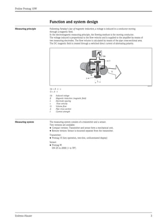
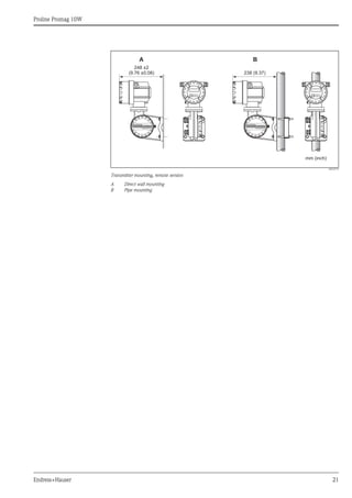
Design, dimensions Transmitter, remote version
A0010718
Transmitter dimensions, remote version
Dimensions in SI units
Dimensions in US units
K
F
E
D
A
H
L
N
O
P
J
G
B C
M
ANSCHLUSSKLEMMEN - FIELD TERMINALS
A B C D E F G Ø H
178 113 135 20 to 30 161 to 181 113 100 8.6 (M8)
J K L M N O P
123 150 100 25 133 177.5 327.5
All dimensions in [mm]
A B C D E F G Ø H
7.00 4.45 5.31 0.79 to 1.81 6.34 to 7.13 4.45 3.94 0.34 (M8)
J K L M N O P
4.84 5.90 3.94 0.98 5.24 6.99 12.89
All dimensions in [inch]](https://image.slidesharecdn.com/prolinepromag10w-endresshauserdatasheet-electromagneticflowmeter-210818172518/85/Proline-promag-10-w-endress-hauser-datasheet-electromagnetic-flowmeter-20-320.jpg)
![Proline Promag 10W
22 Endress+Hauser
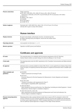
Compact version DN ≤ 300 (12")
A0012464
Dimensions in SI units
DN L 1)
A B C D E F G H J K
EN (DIN) / JIS / AS 2)
25 200
178 20 to 30 161 to 181 113 150
341 257 84 94 120
32 200 341 257 84 94 120
40 200 341 257 84 94 120
50 200 341 257 84 94 120
65 200 391 282 109 94 180
80 200 391 282 109 94 180
100 250 391 282 109 94 180
125 250 472 322 150 140 260
150 300 472 322 150 140 260
200 350 527 347 180 156 324
250 450 577 372 205 166 400
300 500 627 397 230 166 460
1)
The length is regardless of the pressure rating selected. Fitting length to DVGW.
2) For flanges to AS, only the nominal diameters DN 80, 100 and 150 to 300 are available.
All dimensions in [mm]
K
J
L
F
H
G
Esc
E
- +
E
A D
B
C](https://image.slidesharecdn.com/prolinepromag10w-endresshauserdatasheet-electromagneticflowmeter-210818172518/85/Proline-promag-10-w-endress-hauser-datasheet-electromagnetic-flowmeter-22-320.jpg)
![Proline Promag 10W
Endress+Hauser 23
Dimensions in US units
DN L 1)
A B C D E F G H J K
ANSI
1" 7.87
7.01 0.79 to 1.18 6.34 to 7.13 4.45 5.91
13.4 10.1 3.31 3.70 4.72
1½" 7.87 13.4 10.1 3.31 3.70 4.72
2" 7.87 13.4 10.1 3.31 3.70 4.72
3" 7.87 15.4 11.1 4.29 3.70 7.09
4" 9.84 15.4 11.1 4.29 3.70 7.09
6" 11.8 18.6 12.7 5.91 5.51 10.2
8" 13.8 20.8 13.7 7.09 6.14 12.8
10" 17.7 22.7 14.7 8.07 6.14 15.8
12" 19.7 24.7 15.6 9.06 6.54 18.1
1)
The length is regardless of the pressure rating selected. Fitting length to DVGW.
All dimensions in [inch]](https://image.slidesharecdn.com/prolinepromag10w-endresshauserdatasheet-electromagneticflowmeter-210818172518/85/Proline-promag-10-w-endress-hauser-datasheet-electromagnetic-flowmeter-23-320.jpg)
![Proline Promag 10W
24 Endress+Hauser
Compact version DN ≥ 350 (14")
A0003218
Dimensions in SI units
DN L 1)
A B C D E F G H J K
EN (DIN) / AS 2)
350 550
178 20 to 30 161 to 181 113 150
738.5 456.5 282.0 276 564
375 600 790.5 482.5 308.0 276 616
400 600 790.5 482.5 308.0 276 616
450 650 840.5 507.5 333.0 292 666
500 650 891.5 533.0 358.5 292 717
600 780 995.5 585.0 410.5 402 821
700 910 1198.5 686.5 512.0 589 1024
750 975 1198.5 686.5 512.0 626 1024
800 1040 1241.5 708.5 533.5 647 1067
900 1170 1394.5 784.5 610.0 785 1220
1000 1300 1546.5 860.5 686.0 862 1372
1050 1365 1598.5 886.5 712.0 912 1424
1200 1560 1796.5 985.5 811.0 992 1622
1350 1755 1998.5 1086.5 912.0 1252 1824
1400 1820 2148.5 1161.5 987.0 1252 1974
1500 1950 2196.5 1185.5 1011.0 1392 2022
1600 2080 2286.5 1230.5 1056.0 1482 2112
1650 2145 2360.5 1267.5 1093.0 1482 2186
1800 2340 2550.5 1362.5 1188.0 1632 2376
2000 2600 2650.5 1412.5 1238.0 1732 2476
1)
The length is regardless of the pressure rating selected. Fitting length to DVGW.
2)
For flanges to AS, only DN 350, 400, 500 and 600 are available.
All dimensions in [mm]
F
H
G
L
J
K
E
A D
B
C
Esc
E
- +](https://image.slidesharecdn.com/prolinepromag10w-endresshauserdatasheet-electromagneticflowmeter-210818172518/85/Proline-promag-10-w-endress-hauser-datasheet-electromagnetic-flowmeter-24-320.jpg)
![Proline Promag 10W
Endress+Hauser 25
Dimensions in US units
DN L 1)
A B C D E F G H J K
ANSI / AWWA 2)
14" 21.6
7.01 0.79 to 1.18 6.34 to 7.13 4.45 5.91
29.1 17.9 11.1 10.9 22.2
15" 23.6 31.1 18.9 12.1 10.9 24.2
16" 23.6 31.1 18.9 12.1 10.9 24.2
18" 25.6 33.1 19.9 13.1 11.5 26.2
20" 25.6 35.1 20.9 14.1 11.5 28.2
24" 30.7 39.2 23.0 16.2 15.8 32.3
28" 35.8 47.2 27.0 20.1 23.2 40.3
30" 38.4 47.2 27.0 20.1 24.6 40.3
32" 40.9 48.9 27.9 21.0 25.5 42.0
36" 46.0 54.9 30.9 24.0 30.9 48.0
40" 51.2 60.9 33.9 27.0 33.9 54.0
42" 53.7 62.9 34.9 28.0 35.9 56.0
48" 61.4 71.7 38.8 31.9 39.0 63.8
54" 69.1 78.7 42.8 35.9 42.3 71.8
56" 71.7 84.6 45.7 38.9 49.3 77.7
60" 76.8 86.5 46.7 39.8 54.8 79.6
64" 81.9 90.0 48.4 41.6 58.4 83.2
66" 84.4 92.9 49.9 43.0 58.4 86.0
72" 92.1 100.4 53.6 46.8 64.2 93.5
78" 102.3 104.3 55.6 48.7 68.2 97.5
1)
The length is regardless of the pressure rating selected. Fitting length to DVGW.
2) Flanges ≤ DN 600 only to ANSI available, ≥ DN 700 only to AWWA available.
All dimensions in [inch]](https://image.slidesharecdn.com/prolinepromag10w-endresshauserdatasheet-electromagneticflowmeter-210818172518/85/Proline-promag-10-w-endress-hauser-datasheet-electromagnetic-flowmeter-25-320.jpg)
![Proline Promag 10W
26 Endress+Hauser
Sensor, remote version DN ≤ 300 (12")
A0012462
Dimensions in SI units
DN L 1)
A B C D E F G H J
EN (DIN) / JIS / AS 2)
25 200 129 163 143 102 286 202 84 120 94
32 200 129 163 143 102 286 202 84 120 94
40 200 129 163 143 102 286 202 84 120 94
50 200 129 163 143 102 286 202 84 120 94
65 200 129 163 143 102 336 227 109 180 94
80 200 129 163 143 102 336 227 109 180 94
100 250 129 163 143 102 336 227 109 180 94
125 250 129 163 143 102 417 267 150 260 140
150 300 129 163 143 102 417 267 150 260 140
200 350 129 163 143 102 472 292 180 324 156
250 450 129 163 143 102 522 317 205 400 166
300 500 129 163 143 102 572 342 230 460 166
1)
The length is regardless of the pressure rating selected. Fitting length to DVGW.
2) For flanges to AS, only the nominal diameters DN 80, 100 and 150 to 300 are available.
All dimensions in [mm]
J
L
E
G
F
H
B
C
A
D](https://image.slidesharecdn.com/prolinepromag10w-endresshauserdatasheet-electromagneticflowmeter-210818172518/85/Proline-promag-10-w-endress-hauser-datasheet-electromagnetic-flowmeter-26-320.jpg)
![Proline Promag 10W
Endress+Hauser 27
Dimensions in US units
DN L 1)
A B C D E F G H J
ANSI
1" 7.87
5.08 6.42 5.63 4.02
11.3 7.95 3.32 4.72 3.70
1½" 7.87 11.3 7.95 3.32 4.72 3.70
2" 7.87 11.3 7.95 3.32 4.72 3.70
3" 7.87 13.2 8.94 4.30 7.10 3.70
4" 9.84 13.2 8.94 4.30 7.10 3.70
6" 11.8 16.4 10.5 5.91 10.2 5.51
8" 13.8 18.6 11.5 7.10 12.8 6.14
10" 17.7 20.6 12.5 8.08 15.8 6.14
12" 19.7 22.5 13.5 9.06 18.1 6.54
1)
The length is regardless of the pressure rating selected. Fitting length to DVGW.
All dimensions in [inch]](https://image.slidesharecdn.com/prolinepromag10w-endresshauserdatasheet-electromagneticflowmeter-210818172518/85/Proline-promag-10-w-endress-hauser-datasheet-electromagnetic-flowmeter-27-320.jpg)
![Proline Promag 10W
28 Endress+Hauser
Sensor, remote version DN ≥ 350 (14")
A0003220
Dimensions in SI units
DN L 1)
A B C D E F G H J
EN (DIN) / AS 2)
350 550
129 163 143 102
683.5 401.5 282.0 564 276
375 600 735.5 427.5 308.0 616 276
400 600 735.5 427.5 308.0 616 276
450 650 785.5 452.5 333.0 666 292
500 650 836.5 478.0 358.5 717 292
600 780 940.5 530.0 410.5 821 402
700 910 1143.5 631.5 512.0 1024 589
750 975 1143.5 631.5 512.0 1024 626
800 1040 1186.5 653.0 533.5 1067 647
900 1170 1339.5 729.5 610.0 1220 785
1000 1300 1491.5 805.5 686.0 1372 862
1050 1365 1543.5 831.5 712.0 1424 912
1200 1560 1741.5 930.5 811.0 1622 992
1350 1755 1943.5 1031.5 912.0 1824 1252
1400 1820 2093.5 1106.5 987.0 1974 1252
1500 1950 2141.5 1130.5 1011.0 2022 1392
1600 2080 2231.5 1175.5 1056.0 2112 1482
1650 2145 2305.5 1212.5 1093.0 2186 1482
1800 2340 2495.5 1307.5 1188.0 2376 1632
2000 2600 2595.5 1357.5 1238.0 2476 1732
1)
The length is regardless of the pressure rating selected. Fitting length to DVGW.
2)
For flanges to AS, only DN 350, 400, 500 and 600 are available.
All dimensions in [mm]
H
E
G
F
L
J
A B
C
D](https://image.slidesharecdn.com/prolinepromag10w-endresshauserdatasheet-electromagneticflowmeter-210818172518/85/Proline-promag-10-w-endress-hauser-datasheet-electromagnetic-flowmeter-28-320.jpg)
![Proline Promag 10W
Endress+Hauser 29
Dimensions in US units
DN L 1)
A B C D E F G H J
ANSI / AWWA 2)
14" 21.6
5.08 6.42 5.63 4.02
29.1 15.8 11.1 22.2 10.9
15" 23.6 31.1 16.8 12.1 24.2 10.9
16" 23.6 31.1 16.8 12.1 24.2 10.9
18" 25.6 33.1 17.8 13.1 26.2 11.5
20" 25.6 35.1 18.8 14.1 28.2 11.5
24" 30.7 39.2 20.9 16.2 32.3 15.8
28" 35.8 45.0 24.9 20.1 40.3 23.2
30" 38.4 45.0 24.9 20.1 40.3 24.6
32" 40.9 46.7 25.7 21.0 42.0 25.5
36" 46.0 52.7 28.7 24.0 48.0 30.9
40" 51.2 58.7 31.7 27.0 54.0 33.9
42" 53.7 60.7 32.7 28.0 56.0 35.9
48" 61.4 68.5 36.6 31.9 63.8 39.0
54" 69.1 76.5 40.6 35.9 71.8 42.3
56" 71.7 82.4 43.6 38.9 77.7 49.3
60" 76.8 84.3 44.5 39.8 79.6 54.8
64" 81.9 87.9 46.3 41.6 83.2 58.4
66" 84.4 90.8 47.7 43.0 86.0 58.4
72" 92.1 98.2 51.5 46.8 93.5 64.2
78" 102.3 102.2 53.4 48.7 97.5 68.2
1)
The length is regardless of the pressure rating selected. Fitting length to DVGW.
2) Flanges ≤ DN 600 only to ANSI available, ≥ DN 700 only to AWWA available.
All dimensions in [inch]](https://image.slidesharecdn.com/prolinepromag10w-endresshauserdatasheet-electromagneticflowmeter-210818172518/85/Proline-promag-10-w-endress-hauser-datasheet-electromagnetic-flowmeter-29-320.jpg)
![Proline Promag 10W
30 Endress+Hauser
Ground disk for flange connections
A0003221
Dimensions (SI units)
DN 1)
A B C D E t
EN (DIN) / JIS / AS 2)
25 26 62 77.5 87.5
6.5
2
32 35 80 87.5 94.5
40 41 82 101 103
50 52 101 115.5 108
65 68 121 131.5 118
80 80 131 154.5 135
100 104 156 186.5 153
125 130 187 206.5 160
150 158 217 256 184
200 206 267 288 205
250 260 328 359 240
300 3)
312 375 413 273
300 4)
310 375 404 268
350 3) 343 433 479 365
9.0
375 3)
393 480 542 395
400 3)
393 480 542 395
450 3) 439 538 583 417
500 3)
493 592 650 460
600 3)
593 693 766 522
1) Ground disks can be used for all flange standards/pressure ratings that can be delivered, except for DN ≥ 300.
2)
Only DN 32, 40, 65 and 125 are available for flanges according to AS.
3)
PN 10/16
4) PN 25, JIS 10K/20K
All dimensions in [mm]
D
D
Ø B
Ø B
Ø
A
Ø C Ø C
Ø
A
DN 300 (12")
≤ DN 350 (14")
≥
Ø E Ø E
t t](https://image.slidesharecdn.com/prolinepromag10w-endresshauserdatasheet-electromagneticflowmeter-210818172518/85/Proline-promag-10-w-endress-hauser-datasheet-electromagnetic-flowmeter-30-320.jpg)
![Proline Promag 10W
Endress+Hauser 31
Dimensions (US units)
DN 1)
A B C D E t
ANSI
1" 1.02 2.44 3.05 3.44
0.26
0.08
1½" 1.61 3.23 3.98 4.06
2" 2.05 3.98 4.55 4.25
3" 3.15 5.16 6.08 5.31
4" 4.09 6.14 7.34 6.02
6" 6.22 8.54 10.08 7.24
8" 8.11 10.5 11.3 8.07
10" 10.2 12.9 14.1 9.45
12" 12.3 14.8 16.3 10.8
14" 13.5 17.1 18.9 14.4
0.35
15" 15.45 18.9 21.3 15.6
16" 15.45 18.9 21.3 15.6
18" 17.3 21.2 23.0 16.4
20" 19.4 23.3 25.6 18.1
24" 23.4 27.3 30.1 20.6
1) Ground disks can be used for all flange standards/pressure ratings.
All dimensions in [inch]](https://image.slidesharecdn.com/prolinepromag10w-endresshauserdatasheet-electromagneticflowmeter-210818172518/85/Proline-promag-10-w-endress-hauser-datasheet-electromagnetic-flowmeter-31-320.jpg)
![Proline Promag 10W
32 Endress+Hauser
Weight Weight in SI units
Weight data in kg
Diameter Compact version Remote version (without cable)
Sensor Transmitter
[mm] [inch] EN (DIN) /
AS 1)
JIS ANSI /
AWWA
EN (DIN) /
AS 1)
JIS ANSI /
AWWA
Wall housing
25 1"
PN
40
5.7
10K
5.7
Class
150
5.7
PN
40
5.3
10K
5.3
Class
150
5.3
3.1
32 – 6.4 5.7 – 6.0 5.3 –
40 1½" 7.8 6.7 7.8 7.4 6.3 7.4
50 2" 9.0 7.7 9.0 8.6 7.3 8.6
65 –
PN
16
10.4 9.5 –
PN
16
10.0 9.1 –
80 3" 12.4 10.9 12.4 12.0 10.5 12.0
100 4" 14.4 13.1 14.4 14.0 12.7 14.0
125 – 19.9 19.4 – 19.5 19.0 –
150 6" 23.9 22.9 23.9 23.5 22.5 23.5
200 8"
PN
10
43.4 40.3 43.3
PN
10
43 39.9 43
250 10" 63.4 67.8 73.4 63 67.4 73
300 12" 68.4 70.7 108.4 68 70.3 108
350 14"
PN
6
105 175
PN
6
103 173
375 15" 120 – 118 –
400 16" 120 205 118 203
450 18" 161 255 159 253
500 20" 156 285 154 283
600 24" 208 405 206 403
700 28" 304
Class
D
400 302
Class
D
398
– 30" – 460 – 458
800 32" 357 550 355 548
900 36" 485 800 483 798
1000 40" 589 900 587 898
– 42" – 1100 – 1098
1200 48" 850 1400 848 1398
– 54" – 2200 – 2198
1400 – 1300 – 1298 –
– 60" – 2700 – 2698
1600 – 1700 – 1698 –
– 66" – 3700 – 3698
1800 72" 2200 4100 2198 4098
– 78" – 4600 – 4598
2000 – 2800 – 2798 –
1)
For flanges to AS, only DN 80, 100, 150 to 400, 500 and 600 are available.
• Transmitter (compact version): 1.8 kg
• Weight data valid for standard pressure ratings and without packaging material](https://image.slidesharecdn.com/prolinepromag10w-endresshauserdatasheet-electromagneticflowmeter-210818172518/85/Proline-promag-10-w-endress-hauser-datasheet-electromagnetic-flowmeter-32-320.jpg)
![Proline Promag 10W
Endress+Hauser 33
Weight in US units (only ANSI/AWWA)
Weight data in lbs
Diameter Compact version Remote version (without cable)
Sensor Transmitter
[mm] [inch] ANSI /AWWA ANSI / AWWA Wall housing
25 1"
Class
150
12.6
Class
150
11.7
6.8
40 1½" 17.2 16.3
50 2" 19.9 19.0
80 3" 27.3 26.5
100 4" 31.8 30.9
150 6" 52.7 51.8
200 8" 95.5 94.8
250 10" 162.1 161.0
300 12" 239.0 238.1
350 14" 380.1 381.5
400 16" 448.5 447.6
450 18" 558.8 557.9
500 20" 624.9 624.0
600 24" 889.5 888.6
700 28"
Class
D
878.5 Class
D 877.6
– 30" 1010.8 1009.9
800 32" 1209.2 1208.3
900 36" 1760.5 1759.6
1000 40" 1981.0 1980.1
– 42" 2422.0 2421.1
1200 48" 3083.5 3082.6
– 54" 4847.5 4846.6
– 60" 5950.0 5949.1
– 66" 8155.0 8154.1
1800 72" 9037.0 9036.1
– 78" 10139.0 10139.0
• Transmitter (compact version): 4.0 lbs
• Weight data valid for standard pressure ratings and without packaging material](https://image.slidesharecdn.com/prolinepromag10w-endresshauserdatasheet-electromagneticflowmeter-210818172518/85/Proline-promag-10-w-endress-hauser-datasheet-electromagnetic-flowmeter-33-320.jpg)
![Proline Promag 10W
34 Endress+Hauser
Measuring tube specifications Diameter Pressure rating Internal diameter
EN (DIN) AS 2129 AS 4087 ANSI AWWA JIS Hard rubber Polyurethane
[mm] [inch] [bar] [lbs] [mm] [inch] [mm] [inch]
25 1" PN 40 – – Cl. 150 – 20 K – – 24 0.94
32 – PN 40 – – – – 20 K – – 32 1.26
40 1½" PN 40 – – Cl. 150 – 20 K – – 38 1.50
50 2" PN 40 Table E PN 16 Cl. 150 – 10 K 50 1.97 50 1.97
65 – PN 16 – – – – 10 K 66 2.60 66 2.60
80 3" PN 16 Table E PN 16 Cl. 150 – 10 K 79 3.11 79 3.11
100 4" PN 16 Table E PN 16 Cl. 150 – 10 K 102 4.02 102 4.02
125 – PN 16 – – – – 10 K 127 5.00 127 5.00
150 6" PN 16 Table E PN 16 Cl. 150 – 10 K 156 6.14 156 6.14
200 8" PN 10 Table E PN 16 Cl. 150 – 10 K 204 8.03 204 8.03
250 10" PN 10 Table E PN 16 Cl. 150 – 10 K 258 10.2 258 10.2
300 12" PN 10 Table E PN 16 Cl. 150 – 10 K 309 12.2 309 12.2
350 14" PN 6 Table E PN 16 Cl. 150 – – 342 13.5 342 13.5
375 15" – – PN 16 – – – 392 15.4 – –
400 16" PN 6 Table E PN 16 Cl. 150 – – 392 15.4 392 15.4
450 18" PN 6 – – Cl. 150 – – 437 17.2 437 17.2
500 20" PN 6 Table E PN 16 Cl. 150 – – 492 19.4 492 19.4
600 24" PN 6 Table E PN 16 Cl. 150 – – 594 23.4 594 23.4
700 28" PN 6 – – – Class D – 692 27.2 692 27.2
– 30" – – – – Class D – 742 29.2 742 29.2
800 32" PN 6 – – – Class D – 794 31.3 794 31.3
900 36" PN 6 – – – Class D – 891 35.1 891 35.1
1000 40" PN 6 – – – Class D – 994 39.1 994 39.1
– 42" – – – – Class D – 1043 41.1 1043 41.1
1200 48" PN 6 – – – Class D – 1197 47.1 1197 47.1
– 54" – – – Class D – 1339 52.7 – –
1400 – PN 6 – – – – – 1402 55.2 – –
– 60" – – – – Class D – 1492 58.7 – –
1600 – PN 6 – – – – – 1600 63.0 – –
– 66" – – – – Class D – 1638 64.5 – –
1800 72" PN 6 – – – Class D – 1786 70.3 – –
2000 78" PN 6 – – – Class D – 1989 78.3 – –](https://image.slidesharecdn.com/prolinepromag10w-endresshauserdatasheet-electromagneticflowmeter-210818172518/85/Proline-promag-10-w-endress-hauser-datasheet-electromagnetic-flowmeter-34-320.jpg)
![Proline Promag 10W
Endress+Hauser 35
Material • Housing: powder-coated die-cast aluminum
• Sensor housing
– DN 25 to 300 (1 to 12"): powder-coated die-cast aluminum
– DN 350 to 2000 (14 to 78"): with protective lacquering
• Measuring tube
– DN ≤ 300 (12"): stainless steel 1.4301 or 1.4306/304L;
(Flange material: carbon steel with Al/Zn protective coating)
– DN ≥ 350 (14"): stainless steel 1.4301 or 1.4306/304L;
(Flange material: carbon steel with protective lacquering)
• Electrodes: 1.4435/316L, Alloy C-22
• Flanges
– EN 1092-1 (DIN2501): RSt37-2 (S235JRG2); C22, Fe 410W B
(DN ≤ 300 (12"): with Al/Zn protective coating; DN ≥ 350 (14") with protective lacquering)
– ANSI: A105
(DN ≤ 300 (12"): with Al/Zn protective coating; DN ≥ 350 (14") with protective lacquering)
– AWWA: 1.0425 (with protective lacquering)
– JIS: RSt37-2 (S235JRG2); HII; 1.0425
(DN ≤ 300 (12"): with Al/Zn protective coating; DN ≥ 350 (14") with protective lacquering)
– AS 2129
– (DN 25, 80, 100, 150…1200 / 1", 3", 4", 6…48"): A105 or RSt37-2 (S235JRG2)
– (DN 50, 80, 350, 400, 500 / 2", 3", 14", 16", 20"): A105 or St44-2 (S275JR)
– AS 4087: A105 or St44-2 (S275JR)
(DN ≤ 300 (12"): with Al/Zn protective coating; DN ≥ 350 (14") with protective lacquering)
• Seals: to DIN EN 1514-1
• Ground disks: 1.4435/316L or Alloy C-22
Material load diagram Caution!
The following diagrams contain material load diagrams (reference curves) for flange materials with regard to
the medium temperature. However, the maximum medium temperatures permitted always depend on the
lining material of the sensor and/or the sealing material.
Flange connection to EN 1092-1 (DIN 2501)
Material: RSt37-2 (S235JRG2) / C22 / Fe 410W B
A0005594
PN25
PN16
PN10
PN 6
PN40
0
5
10
15
20
25
35
30
40
[bar]
[psi]
-60 -40 -20 0 20 40 60 80 100 120 140 160 180 [°C]
360 [°F]
0
-40 100 200 300
200
100
400
300
500
600
0](https://image.slidesharecdn.com/prolinepromag10w-endresshauserdatasheet-electromagneticflowmeter-210818172518/85/Proline-promag-10-w-endress-hauser-datasheet-electromagnetic-flowmeter-35-320.jpg)
![Proline Promag 10W
36 Endress+Hauser
Flanschanschluss nach EN 1092-1 (DIN 2501)
Werkstoff: 316L / 1.4571
A0005304
Flange connection to ANSI B16.5
Material: A 105
A0003226
Flanschanschluss nach ANSI B16.5
Werkstoff: F316L
A0005307
PN25
PN16
PN10
PN40
PN 6
0
5
10
15
20
25
35
30
40
[bar]
[psi]
-60 -40 -20 0 20 40 60 80 100 120 140 160 180 [°C]
360 [°F]
0
-40 100 200 300
200
100
400
300
500
600
0
Class300
Class150
0
10
20
30
40
50
[bar]
[psi]
-40 -20 0 20 40 60 80 100 120 140 160 180 [°C]
360 [°F]
0
-40 100 200 300
200
100
400
300
500
600
700
800
900
0
60
Class300
Class150
0
10
20
30
40
50
[bar]
[psi]
-40 -20 0 20 40 60 80 100 120 140 160 180 [°C]
360 [°F]
0
-40 100 200 300
200
100
400
300
500
600
700
800
900
0
60](https://image.slidesharecdn.com/prolinepromag10w-endresshauserdatasheet-electromagneticflowmeter-210818172518/85/Proline-promag-10-w-endress-hauser-datasheet-electromagnetic-flowmeter-36-320.jpg)
![Proline Promag 10W
Endress+Hauser 37
Flange connection to AWWA C207, Class D
Material: 1.0425
A0005592
Flange connection to JIS B2220
Material: RSt37-2 (S235JRG2) / HII / 1.0425 / 316L
A0003228
Flange connection to AS 2129 Table E or AS 4087 PN 16
Material: A105 / RSt37-2 (S235JRG2) / St44-2 (S275JR)
A0005595
Fitted electrodes Measuring electrodes, reference electrodes and empty pipe detection electrodes available as standard with:
• 1.4435
• Alloy C-22
0
7
8
9
10
11
[bar]
0
101,5
116
130,5
145
159,5
[psi]
-60 -40 -20 0 20 40 60 80 100 120 140 160 [°C]
10K
20K
-40 -20 0 20 40 60 80 100 120 140 160 180 [°C]
0
10
20
30
[bar]
360 [°F]
0
-40 100 200 300
[psi]
200
100
400
300
0
-40 -20 0 20 40 60 80 100 120 140 160 [°C]
0
10
5
20
15
[bar]
0
-40 100 200 300 [°F]
[psi]
200
100
300
0
TableE
PN16](https://image.slidesharecdn.com/prolinepromag10w-endresshauserdatasheet-electromagneticflowmeter-210818172518/85/Proline-promag-10-w-endress-hauser-datasheet-electromagnetic-flowmeter-37-320.jpg)

The document provides technical information about the Proline Promag 10W electromagnetic flow measuring system, detailing its application for measuring the flow of liquids in water and wastewater, with a conductivity minimum of ≥ 50 μs/cm and operational parameters such as flow measurement up to 110,000 m³/h and fluid temperature up to +80 °C. It describes the system's components, including the compact and remote versions, and highlights features like high measuring stability, simple installation, and various configuration options for output signals. Additionally, the document outlines the installation instructions, operating conditions, compatibility, and certification details relevant to the Proline Promag 10W system.


