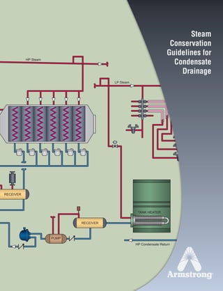
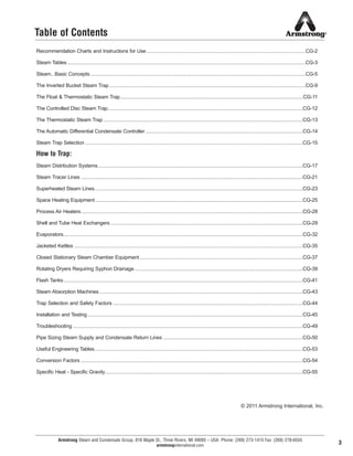
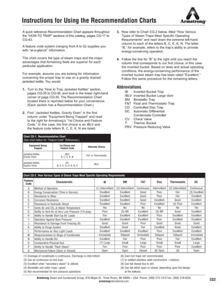
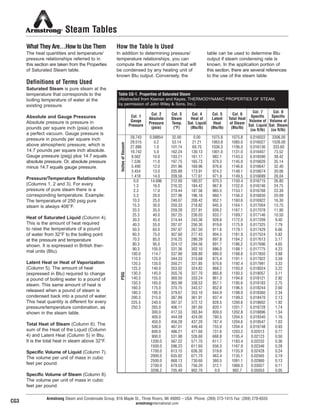
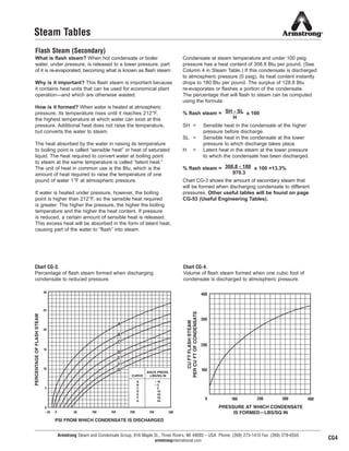
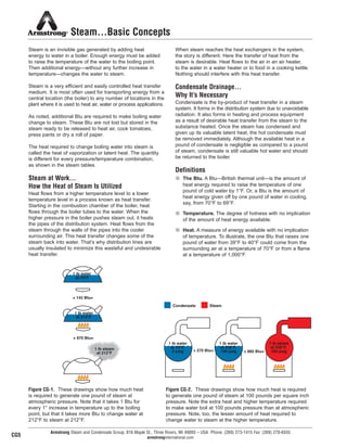
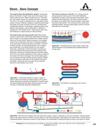
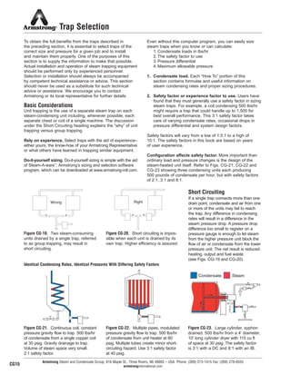
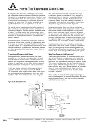
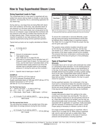
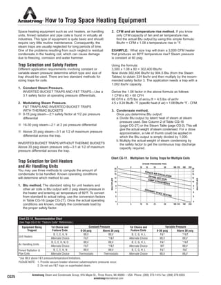
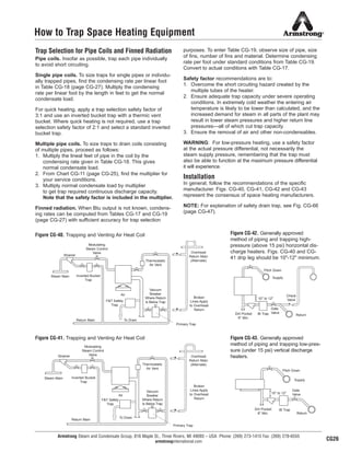
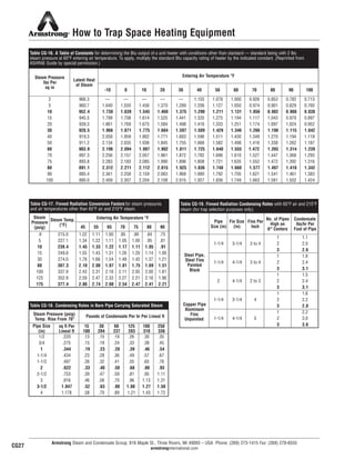
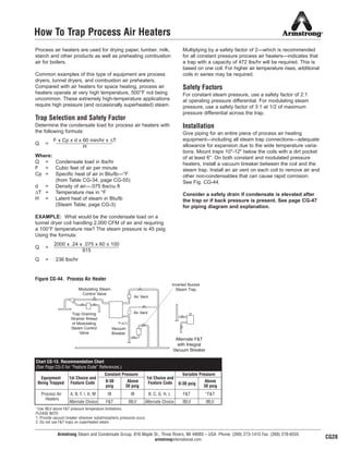
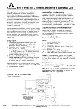
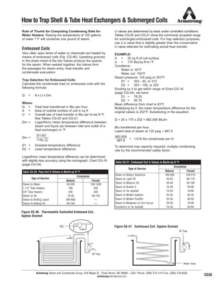
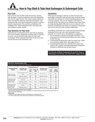
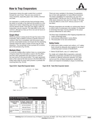
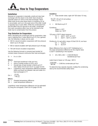
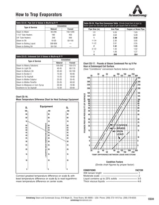
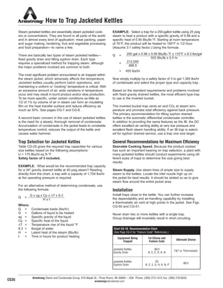
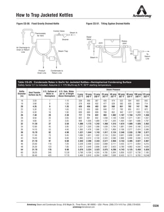
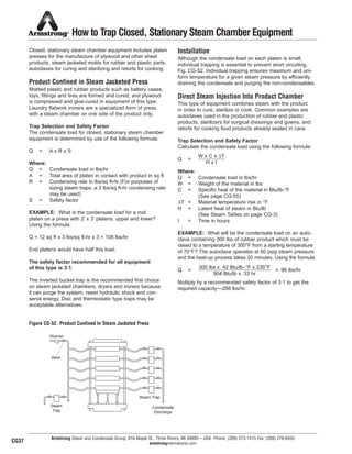
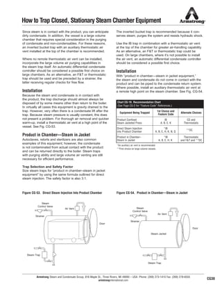
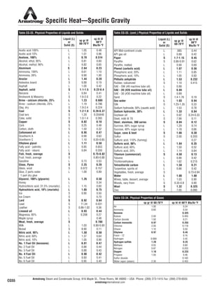
HP Steam
HP Condensate Return
LP Steam
TANK HEATER
H
K
RECEIVER
PUMP
RECEIVER
Steam
Conservation
Guidelines for
Condensate
Drainage
Armstrong Steam and Condensate Group, 816 Maple St., Three Rivers, MI 49093 – USA Phone: (269) 273-1415 Fax: (269) 278-6555
armstronginternational.com
Table of Contents
3
Recommendation Charts and Instructions for Use ......................................................................................................................CG-2
Steam Tables .................................................................................................................................................................................CG-3
Steam...Basic Concepts................................................................................................................................................................CG-5
The Inverted Bucket Steam Trap..................................................................................................................................................CG-9
The Float & Thermostatic Steam Trap........................................................................................................................................CG-11
The Controlled Disc Steam Trap.................................................................................................................................................CG-12
The Thermostatic Steam Trap ....................................................................................................................................................CG-13
The Automatic Differential Condensate Controller.....................................................................................................................CG-14
Steam Trap Selection..................................................................................................................................................................CG-15
How to Trap:
Steam Distribution Systems........................................................................................................................................................CG-17
Steam Tracer Lines .....................................................................................................................................................................CG-21
Superheated Steam Lines...........................................................................................................................................................CG-23
Space Heating Equipment ..........................................................................................................................................................CG-25
Process Air Heaters.....................................................................................................................................................................CG-28
Shell and Tube Heat Exchangers...............................................................................................................................................CG-29
Evaporators..................................................................................................................................................................................CG-32
Jacketed Kettles ..........................................................................................................................................................................CG-35
Closed Stationary Steam Chamber Equipment .........................................................................................................................CG-37
Rotating Dryers Requiring Syphon Drainage.............................................................................................................................CG-39
Flash Tanks..................................................................................................................................................................................CG-41
Steam Absorption Machines .......................................................................................................................................................CG-43
Trap Selection and Safety Factors .............................................................................................................................................CG-44
Installation and Testing................................................................................................................................................................CG-45
Troubleshooting ...........................................................................................................................................................................CG-49
Pipe Sizing Steam Supply and Condensate Return Lines ........................................................................................................CG-50
Useful Engineering Tables...........................................................................................................................................................CG-53
Conversion Factors .....................................................................................................................................................................CG-54
Specific Heat - Specific Gravity...................................................................................................................................................CG-55
© 2011 Armstrong International, Inc.
13800 N101-Revised 2-11_838_Cons_Guide.qxd 2/8/11 10:13 AM Page 5
Bringing Energy Down to Earth
Say energy. Think environment. And vice versa.
Any company that is energy conscious is also environmentally
conscious. Less energy consumed means less waste, fewer
emissions and a healthier environment.
In short, bringing energy and environment together lowers
the cost industry must pay for both. By helping companies
manage energy, Armstrong products and services are also
helping to protect the environment.
Armstrong has been sharing know-how since we invented
the energy-efficient inverted bucket steam trap in 1911. In the
years since, customers’ savings have proven again and again
that knowledge not shared is energy wasted.
Armstrong’s developments and improvements in steam trap
design and function have led to countless savings in energy,
time and money. This section has grown out of our decades
of sharing and expanding what we’ve learned. It deals with the
operating principles of steam traps and outlines their specific
applications to a wide variety of products and industries.
You’ll find it a useful complement to other Armstrong literature
and the Armstrong Steam-A-ware™
software program for sizing
and selecting steam traps, pressure reducing valves and
water heaters, which can be requested through Armstrong’s
Web site, armstronginternational.com.
This section also includes Recommendation Charts that
summarize our findings on which type of trap will give
optimum performance in a given situation and why.
Armstrong Steam and Condensate Group, 816 Maple St., Three Rivers, MI 49093 – USA Phone: (269) 273-1415 Fax: (269) 278-6555
armstronginternational.com
IMPORTANT: This section is intended to summarize
general principles of installation and operation of steam
traps, as outlined above. Actual installation and operation
of steam trapping equipment should be performed
only by experienced personnel. Selection or installation
should always be accompanied by competent technical
assistance or advice. This data should never be used
as a substitute for such technical advice or assistance.
We encourage you to contact Armstrong or its local
representative for further details.
CG-1
13808 N101-Revised 2-11_838_Cons_Guide.qxd 2/3/11 12:24 PM Page CG1
Armstrong Steam and Condensate Group, 816 Maple St., Three Rivers, MI 49093 – USA Phone: (269) 273-1415 Fax: (269) 278-6555
armstronginternational.com
Instructions for Using the Recommendation Charts
A quick reference Recommendation Chart appears throughout
the “HOW TO TRAP” sections of this catalog, pages CG-17 to
CG-43.
A feature code system (ranging from A to Q) supplies you
with “at-a-glance” information.
The chart covers the type of steam traps and the major
advantages that Armstrong feels are superior for each
particular application.
For example, assume you are looking for information
concerning the proper trap to use on a gravity drained
jacketed kettle. You would:
1. Turn to the “How to Trap Jacketed Kettles” section,
pages CG-35 to CG-36, and look in the lower right-hand
corner of page CG-35. The Recommendation Chart
located there is reprinted below for your convenience.
(Each section has a Recommendation Chart.)
2. Find “Jacketed Kettles, Gravity Drain” in the first
column under “Equipment Being Trapped” and read
to the right for Armstrong’s “1st Choice and Feature
Code.” In this case, the first choice is an IBLV and
the feature code letters B, C, E, K, N are listed.
3. Now refer to Chart CG-2 below, titled “How Various
Types of Steam Traps Meet Specific Operating
Requirements” and read down the extreme left-hand
column to each of the letters B, C, E, K, N. The letter
“B,” for example, refers to the trap’s ability to provide
energy-conserving operation.
4. Follow the line for “B” to the right until you reach the
column that corresponds to our first choice, in this case
the inverted bucket. Based on tests and actual operating
conditions, the energy-conserving performance of the
inverted bucket steam trap has been rated “Excellent.”
Follow this same procedure for the remaining letters.
Abbreviations
IB Inverted Bucket Trap
IBLV Inverted Bucket Large Vent
BM Bimetallic Trap
F&T Float and Thermostatic Trap
CD Controlled Disc Trap
DC Automatic Differential
Condensate Controller
CV Check Valve
T Thermic Bucket
PRV Pressure Reducing Valve
(1) Drainage of condensate is continuous. Discharge is intermittent. (6) Cast iron traps not recommended.
(2) Can be continuous on low load. (7) In welded stainless steel construction – medium.
(3) Excellent when “secondary steam” is utilized. (8) Can fail closed due to dirt.
(4) Bimetallic and wafer traps – good. (9) Can fail either open or closed, depending upon the design
(5) Not recommended for low pressure operations. of the bellows.
CG2
Equipment Being
Trapped
1st Choice and
Feature Code
Alternate Choice
Jacketed Kettles
Gravity Drain
IBLV
B, C, E, K, N
F&T or Thermostatic
Jacketed Kettles
Syphon Drain
DC
B, C, E, G, H, K, N, P
IBLV
Chart CG-1. Recommendation Chart
(See chart below for “Feature Code” References.)
Feature
Code
Characteristic IB BM F&T Disc Thermostatic DC
A Method of Operation (1) Intermittent (2) Intermittent Continuous Intermittent (2) Intermittent Continuous
B Energy Conservation (Time in Service) Excellent Excellent Good Poor Fair (3) Excellent
C Resistance to Wear Excellent Excellent Good Poor Fair Excellent
D Corrosion Resistance Excellent Excellent Good Excellent Good Excellent
E Resistance to Hydraulic Shock Excellent Excellent Poor Excellent (4) Poor Excellent
F Vents Air and CO2 at Steam Temperature Yes No No No No Yes
G Ability to Vent Air at Very Low Pressure (1/4 psig) Poor (5) NR Excellent (5) NR Good Excellent
H Ability to Handle Start-Up Air Loads Fair Excellent Excellent Poor Excellent Excellent
I Operation Against Back Pressure Excellent Excellent Excellent Poor Excellent Excellent
J Resistance to Damage From Freezing (6) Good Good Poor Good Good Good
K Ability to Purge System Excellent Good Fair Excellent Good Excellent
L Performance on Very Light Loads Excellent Excellent Excellent Poor Excellent Excellent
M Responsiveness to Slugs of Condensate Immediate Delayed Immediate Delayed Delayed Immediate
N Ability to Handle Dirt Excellent Fair Poor Poor Fair Excellent
O Comparative Physical Size (7) Large Small Large Small Small Large
P Ability to Handle “Flash Steam” Fair Poor Poor Poor Poor Excellent
Q Mechanical Failure (Open or Closed) Open Open Closed (8) Open (9) Open
Chart CG-2. How Various Types of Steam Traps Meet Specific Operating Requirements
13808 N101-Revised 2-11_838_Cons_Guide.qxd 2/3/11 12:24 PM Page CG2
Armstrong Steam and Condensate Group, 816 Maple St., Three Rivers, MI 49093 – USA Phone: (269) 273-1415 Fax: (269) 278-6555
armstronginternational.com
What They Are…How to Use Them
The heat quantities and temperature/
pressure relationships referred to in
this section are taken from the Properties
of Saturated Steam table.
Definitions of Terms Used
Saturated Steam is pure steam at the
temperature that corresponds to the
boiling temperature of water at the
existing pressure.
Absolute and Gauge Pressures
Absolute pressure is pressure in
pounds per square inch (psia) above
a perfect vacuum. Gauge pressure is
pressure in pounds per square inch
above atmospheric pressure, which is
14.7 pounds per square inch absolute.
Gauge pressure (psig) plus 14.7 equals
absolute pressure. Or, absolute pressure
minus 14.7 equals gauge pressure.
Pressure/Temperature Relationship
(Columns 1, 2 and 3). For every
pressure of pure steam there is a
corresponding temperature. Example:
The temperature of 250 psig pure
steam is always 406°F.
Heat of Saturated Liquid (Column 4).
This is the amount of heat required
to raise the temperature of a pound
of water from 32°F to the boiling point
at the pressure and temperature
shown. It is expressed in British ther-
mal units (Btu).
Latent Heat or Heat of Vaporization
(Column 5). The amount of heat
(expressed in Btu) required to change
a pound of boiling water to a pound of
steam. This same amount of heat is
released when a pound of steam is
condensed back into a pound of water.
This heat quantity is different for every
pressure/temperature combination, as
shown in the steam table.
Total Heat of Steam (Column 6). The
sum of the Heat of the Liquid (Column
4) and Latent Heat (Column 5) in Btu.
It is the total heat in steam above 32°F.
Specific Volume of Liquid (Column 7).
The volume per unit of mass in cubic
feet per pound.
Specific Volume of Steam (Column 8).
The volume per unit of mass in cubic
feet per pound.
How the Table Is Used
In addition to determining pressure/
temperature relationships, you can
compute the amount of steam that will
be condensed by any heating unit of
known Btu output. Conversely, the
table can be used to determine Btu
output if steam condensing rate is
known. In the application portion of
this section, there are several references
to the use of the steam table.
Steam Tables
Table CG-1. Properties of Saturated Steam
(Abstracted from Keenan and Keyes, THERMODYNAMIC PROPERTIES OF STEAM,
by permission of John Wiley & Sons, Inc.)
Col. 1
Gauge
Pressure
Col. 2
Absolute
Pressure
(psia)
Col. 3
Steam
Temp.
(°F)
Col. 4
Heat of
Sat. Liquid
(Btu/lb)
Col. 5
Latent
Heat
(Btu/lb)
Col. 6
Total Heat
of Steam
(Btu/lb)
Col. 7
Specific
Volume of
Sat. Liquid
(cu ft/lb)
Col. 8
Specific
Volume of
Sat. Steam
(cu ft/lb)
29.743 0.08854 32.00 0.00 1075.8 1075.8 0.016022 3306.00
29.515 0.2 53.14 21.21 1063.8 1085.0 0.016027 1526.00
27.886 1.0 101.74 69.70 1036.3 1106.0 0.016136 333.60
19.742 5.0 162.24 130.13 1001.0 1131.0 0.016407 73.52
9.562 10.0 193.21 161.17 982.1 1143.3 0.016590 38.42
7.536 11.0 197.75 165.73 979.3 1145.0 0.016620 35.14
5.490 12.0 201.96 169.96 976.6 1146.6 0.016647 32.40
3.454 13.0 205.88 173.91 974.2 1148.1 0.016674 30.06
1.418 14.0 209.56 177.61 971.9 1149.5 0.016699 28.04
0.0 14.696 212.00 180.07 970.3 1150.4 0.016715 26.80
1.3 16.0 216.32 184.42 967.6 1152.0 0.016746 24.75
2.3 17.0 219.44 187.56 965.5 1153.1 0.016768 23.39
5.3 20.0 227.96 196.16 960.1 1156.3 0.016830 20.09
10.3 25.0 240.07 208.42 952.1 1160.6 0.016922 16.30
15.3 30.0 250.33 218.82 945.3 1164.1 0.017004 13.75
20.3 35.0 259.28 227.91 939.2 1167.1 0.017078 11.90
25.3 40.0 267.25 236.03 933.7 1169.7 0.017146 10.50
30.3 45.0 274.44 243.36 928.6 1172.0 0.017209 9.40
40.3 55.0 287.07 256.30 919.6 1175.9 0.017325 7.79
50.3 65.0 297.97 267.50 911.6 1179.1 0.017429 6.66
60.3 75.0 307.60 277.43 904.5 1181.9 0.017524 5.82
70.3 85.0 316.25 286.39 897.8 1184.2 0.017613 5.17
80.3 95.0 324.12 294.56 891.7 1186.2 0.017696 4.65
90.3 105.0 331.36 302.10 886.0 1188.1 0.017775 4.23
100.0 114.7 337.90 308.80 880.0 1188.8 0.017850 3.88
110.3 125.0 344.33 315.68 875.4 1191.1 0.017922 3.59
120.3 135.0 350.21 321.85 870.6 1192.4 0.017991 3.33
125.3 140.0 353.02 324.82 868.2 1193.0 0.018024 3.22
130.3 145.0 355.76 327.70 865.8 1193.5 0.018057 3.11
140.3 155.0 360.50 333.24 861.3 1194.6 0.018121 2.92
150.3 165.0 365.99 338.53 857.1 1195.6 0.018183 2.75
160.3 175.0 370.75 343.57 852.8 1196.5 0.018244 2.60
180.3 195.0 379.67 353.10 844.9 1198.0 0.018360 2.34
200.3 215.0 387.89 361.91 837.4 1199.3 0.018470 2.13
225.3 240.0 397.37 372.12 828.5 1200.6 0.018602 1.92
250.3 265.0 406.11 381.60 820.1 1201.7 0.018728 1.74
300.0 417.33 393.84 809.0 1202.8 0.018896 1.54
400.0 444.59 424.00 780.5 1204.5 0.019340 1.16
450.0 456.28 437.20 767.4 1204.6 0.019547 1.03
500.0 467.01 449.40 755.0 1204.4 0.019748 0.93
600.0 486.21 471.60 731.6 1203.2 0.02013 0.77
900.0 531.98 526.60 668.8 1195.4 0.02123 0.50
1200.0 567.22 571.70 611.7 1183.4 0.02232 0.36
1500.0 596.23 611.60 556.3 1167.9 0.02346 0.28
1700.0 613.15 636.30 519.6 1155.9 0.02428 0.24
2000.0 635.82 671.70 463.4 1135.1 0.02565 0.19
2500.0 668.13 730.60 360.5 1091.1 0.02860 0.13
2700.0 679.55 756.20 312.1 1068.3 0.03027 0.11
3206.2 705.40 902.70 0.0 902.7 0.05053 0.05
InchesofVacuumPSIG
CG3
8
13808 N101-Revised 2-11_838_Cons_Guide.qxd 2/3/11 12:24 PM Page CG3
400
300
200
100
0 100 200 300 400
PRESSURE AT WHICH CONDENSATE
IS FORMED—LBS/SQ IN
CUFTFLASHSTEAM
PERCUFTOFCONDENSATE
30
0
5
10
15
20
25
–20 300250200150100500
PERCENTAGEOFFLASHSTEAM
PSI FROM WHICH CONDENSATE IS DISCHARGED
CURVE
BACK PRESS.
LBS/SQ IN
A
B
C
D
E
F
G
10
5
0
10
20
30
40
–
–
B
C
D
E
F
A
G
Armstrong Steam and Condensate Group, 816 Maple St., Three Rivers, MI 49093 – USA Phone: (269) 273-1415 Fax: (269) 278-6555
armstronginternational.com
Steam Tables
Flash Steam (Secondary)
What is flash steam? When hot condensate or boiler
water, under pressure, is released to a lower pressure, part
of it is re-evaporated, becoming what is known as flash steam.
Why is it important? This flash steam is important because
it contains heat units that can be used for economical plant
operation—and which are otherwise wasted.
How is it formed? When water is heated at atmospheric
pressure, its temperature rises until it reaches 212°F,
the highest temperature at which water can exist at this
pressure. Additional heat does not raise the temperature,
but converts the water to steam.
The heat absorbed by the water in raising its temperature
to boiling point is called “sensible heat” or heat of saturated
liquid. The heat required to convert water at boiling point
to steam at the same temperature is called “latent heat.”
The unit of heat in common use is the Btu, which is the
amount of heat required to raise the temperature of one
pound of water 1°F at atmospheric pressure.
If water is heated under pressure, however, the boiling
point is higher than 212°F, so the sensible heat required
is greater. The higher the pressure, the higher the boiling
temperature and the higher the heat content. If pressure
is reduced, a certain amount of sensible heat is released.
This excess heat will be absorbed in the form of latent heat,
causing part of the water to “flash” into steam.
Condensate at steam temperature and under 100 psig
pressure has a heat content of 308.8 Btu per pound. (See
Column 4 in Steam Table.) If this condensate is discharged
to atmospheric pressure (0 psig), its heat content instantly
drops to 180 Btu per pound. The surplus of 128.8 Btu
re-evaporates or flashes a portion of the condensate.
The percentage that will flash to steam can be computed
using the formula:
% flash steam = x 100
SH = Sensible heat in the condensate at the higher
pressure before discharge.
SL = Sensible heat in the condensate at the lower
pressure to which discharge takes place.
H = Latent heat in the steam at the lower pressure
to which the condensate has been discharged.
% flash steam = x 100 =13.3%
Chart CG-3 shows the amount of secondary steam that
will be formed when discharging condensate to different
pressures. Other useful tables will be found on page
CG-53 (Useful Engineering Tables).
SH - SL
H
308.8 - 180
970.3
Chart CG-3.
Percentage of flash steam formed when discharging
condensate to reduced pressure.
Chart CG-4.
Volume of flash steam formed when one cubic foot of
condensate is discharged to atmospheric pressure.
CG4
9
13808 N101-Revised 2-11_838_Cons_Guide.qxd 2/3/11 12:24 PM Page CG4
+ 880 Btu=
1 lb water
at 70°F,
0 psig
1 lb water
at 338°F,
100 psig+ 270 Btu=
1 lb steam
at 338°F,
100 psig
Condensate Steam
1 lb water
at 70°F
1 lb water
at 212°F
1 lb steam
at 212°F
+ 970 Btu=
+ 142 Btu=
Steam…Basic Concepts
Steam is an invisible gas generated by adding heat
energy to water in a boiler. Enough energy must be added
to raise the temperature of the water to the boiling point.
Then additional energy—without any further increase in
temperature—changes the water to steam.
Steam is a very efficient and easily controlled heat transfer
medium. It is most often used for transporting energy from a
central location (the boiler) to any number of locations in the
plant where it is used to heat air, water or process applications.
As noted, additional Btu are required to make boiling water
change to steam. These Btu are not lost but stored in the
steam ready to be released to heat air, cook tomatoes,
press pants or dry a roll of paper.
The heat required to change boiling water into steam is
called the heat of vaporization or latent heat. The quantity
is different for every pressure/temperature combination,
as shown in the steam tables.
Steam at Work…
How the Heat of Steam Is Utilized
Heat flows from a higher temperature level to a lower
temperature level in a process known as heat transfer.
Starting in the combustion chamber of the boiler, heat
flows through the boiler tubes to the water. When the
higher pressure in the boiler pushes steam out, it heats
the pipes of the distribution system. Heat flows from the
steam through the walls of the pipes into the cooler
surrounding air. This heat transfer changes some of the
steam back into water. That’s why distribution lines are
usually insulated to minimize this wasteful and undesirable
heat transfer.
When steam reaches the heat exchangers in the system,
the story is different. Here the transfer of heat from the
steam is desirable. Heat flows to the air in an air heater,
to the water in a water heater or to food in a cooking kettle.
Nothing should interfere with this heat transfer.
Condensate Drainage…
Why It’s Necessary
Condensate is the by-product of heat transfer in a steam
system. It forms in the distribution system due to unavoidable
radiation. It also forms in heating and process equipment
as a result of desirable heat transfer from the steam to the
substance heated. Once the steam has condensed and
given up its valuable latent heat, the hot condensate must
be removed immediately. Although the available heat in a
pound of condensate is negligible as compared to a pound
of steam, condensate is still valuable hot water and should
be returned to the boiler.
Definitions
n The Btu. A Btu—British thermal unit—is the amount of
heat energy required to raise the temperature of one
pound of cold water by 1°F. Or, a Btu is the amount of
heat energy given off by one pound of water in cooling,
say, from 70°F to 69°F.
n Temperature. The degree of hotness with no implication
of the amount of heat energy available.
n Heat. A measure of energy available with no implication
of temperature. To illustrate, the one Btu that raises one
pound of water from 39°F to 40°F could come from the
surrounding air at a temperature of 70°F or from a flame
at a temperature of 1,000°F.
Armstrong Steam and Condensate Group, 816 Maple St., Three Rivers, MI 49093 – USA Phone: (269) 273-1415 Fax: (269) 278-6555
armstronginternational.com
Figure CG-1. These drawings show how much heat
is required to generate one pound of steam at
atmospheric pressure. Note that it takes 1 Btu for
every 1° increase in temperature up to the boiling
point, but that it takes more Btu to change water at
212°F to steam at 212°F.
Figure CG-2. These drawings show how much heat is required
to generate one pound of steam at 100 pounds per square inch
pressure. Note the extra heat and higher temperature required
to make water boil at 100 pounds pressure than at atmospheric
pressure. Note, too, the lesser amount of heat required to
change water to steam at the higher temperature.
CG5
13808 N101-Revised 2-11_838_Cons_Guide.qxd 2/3/11 12:24 PM Page CG5
100 psig
337.9°F
50.3 psig
297.97°F
Trap
Trap
Trap
Trap
Trap
Vent
PRV
Trap
A B
Armstrong Steam and Condensate Group, 816 Maple St., Three Rivers, MI 49093 – USA Phone: (269) 273-1415 Fax: (269) 278-6555
armstronginternational.com
Steam…Basic Concepts
The need to drain the distribution system. Condensate
lying in the bottom of steam lines can be the cause of one
kind of water hammer. Steam traveling at up to 100 miles
per hour makes “waves” as it passes over this condensate
Fig. CG-4). If enough condensate forms, high-speed steam
pushes it along, creating a dangerous slug that grows larger
and larger as it picks up liquid in front of it. Anything that
changes the direction—pipe fittings, regulating valves, tees,
elbows, blind flanges—can be destroyed. In addition to
damage from this “battering ram,” high-velocity water may
erode fittings by chipping away at metal surfaces.
The need to drain the heat transfer unit. When steam
comes in contact with condensate cooled below the temper-
ature of steam, it can produce another kind of water hammer
known as thermal shock. Steam occupies a much greater
volume than condensate, and when it collapses suddenly,
it can send shock waves throughout the system. This form
of water hammer can damage equipment, and it signals
that condensate is not being drained from the system.
Obviously, condensate in the heat transfer unit takes up
space and reduces the physical size and capacity of the
equipment. Removing it quickly keeps the unit full of steam
(Fig. CG-5). As steam condenses, it forms a film of water on
the inside of the heat exchanger. Non-condensable gases
do not change into liquid and flow away by gravity. Instead,
they accumulate as a thin film on the surface of the heat
exchanger—along with dirt and scale. All are potential
barriers to heat transfer (Fig. CG-3).
The need to remove air and CO2. Air is always present
during equipment start-up and in the boiler feedwater.
Feedwater may also contain dissolved carbonates, which
release carbon dioxide gas. The steam velocity pushes
the gases to the walls of the heat exchangers, where they
may block heat transfer. This compounds the condensate
drainage problem, because these gases must be removed
along with the condensate.
Figure CG-3. Potential barriers to heat transfer: steam heat
and temperature must penetrate these potential barriers to
do their work.
Figure CG-6. Note that heat radiation from the distribution system causes condensate to form and, therefore, requires steam
traps at natural low points or ahead of control valves. In the heat exchangers, traps perform the vital function of removing the
condensate before it becomes a barrier to heat transfer. Hot condensate is returned through the traps to the boiler for reuse.
Figure CG-5. Coil half full of condensate can’t work at
full capacity.
Figure CG-4. Condensate allowed to collect in pipes or
tubes is blown into waves by steam passing over it until it
blocks steam flow at point A. Condensate in area B causes
a pressure differential that allows steam pressure to push
the slug of condensate along like a battering ram.
CG6
11
Condensate Steam Vapor
13808 N101-Revised 2-11_838_Cons_Guide.qxd 2/3/11 12:24 PM Page CG6
450
425
400
375
350
325
300
275
250
225
200
150
100
300 250
200 150
100 75 50 25 0 100 90
80
70
60
50
40
30
20
10
0
100 90
80
70
60
50
40
30
20
10
0
PERCENT AIR BY VOLUME–%
PRESSURE–PSIG
300 250
200
150 100 75 50 25 0
0
450
425
400
375
350
325
300
275
250
225
200
150
100
0
TEMPERATUREF
Steam…Basic Concepts
Effect of Air on Steam Temperature
When air and other gases enter the steam system, they
consume part of the volume that steam would otherwise
occupy. The temperature of the air/steam mixture falls below
that of pure steam. Figure CG-7 explains the effect of air
in steam lines. Table CG-2 and Chart CG-5 show the vari-
ous temperature reductions caused by air at various per-
centages and pressures.
Effect of Air on Heat Transfer
The normal flow of steam toward the heat exchanger sur-
face carries air and other gases with it. Since they do not
condense and drain by gravity, these non-condensable
gases set up a barrier between the steam and the heat
exchanger surface. The excellent insulating properties of
air reduce heat transfer. In fact, under certain conditions
as little as 1/2 of 1% by volume of air in steam can reduce
heat transfer efficiency by 50% (Fig. CG-8).
When non-condensable gases (primarily air) continue to
accumulate and are not removed, they may gradually fill
the heat exchanger with gases and stop the flow of steam
altogether. The unit is then “air bound.”
Corrosion
Two primary causes of scale and corrosion are carbon
dioxide (CO2) and oxygen. CO2 enters the system as
carbonates dissolved in feedwater and, when mixed with
cooled condensate, creates carbonic acid. Extremely
corrosive, carbonic acid can eat through piping and heat
exchangers (Fig. CG-9). Oxygen enters the system as gas
dissolved in the cold feedwater. It aggravates the action of
carbonic acid, speeding corrosion and pitting iron and steel
surfaces (Fig. CG-10).
Eliminating the Undesirables
To summarize, traps must drain condensate because
it can reduce heat transfer and cause water hammer.
Traps should evacuate air and other non-condensable
gases because they can reduce heat transfer by reducing
steam temperature and insulating the system. They can
also foster destructive corrosion. It’s essential to remove
condensate, air and CO2 as quickly and completely as
possible. A steam trap, which is simply an automatic valve
that opens for condensate, air and CO2 and closes for
steam, does this job. For economic reasons, the steam trap
should do its work for long periods with minimum attention.
Armstrong Steam and Condensate Group, 816 Maple St., Three Rivers, MI 49093 – USA Phone: (269) 273-1415 Fax: (269) 278-6555
armstronginternational.com
Chart CG-5. Air Steam Mixture
Temperature reduction caused by various percentages of air at differing pres-
sures. This chart determines the percentage of air with known pressure and tem-
perature by determining the point of intersection between pressure, temperature
and percentage of air by volume. As an example, assume system pressure of 250
psig with a temperature at the heat exchanger of 375°F. From the chart, it is deter-
mined that there is 30% air by volume in the steam.
Figure CG-7. Chamber containing air
and steam delivers only the heat of the
partial pressure of the steam, not the
total pressure.
Steam chamber 100% steam
Total pressure 100 psia
Steam pressure 100 psia
Steam temperature 327.8°F
Steam chamber 90% steam and 10% air
Total pressure 100 psia
Steam pressure 90 psia
Steam temperature 320.3°F
Pressure
(psig)
Temp. of
Steam, No Air
Present (°F)
10% 20% 30%
10.3 240.1 234.3 228.0 220.9
25.3 267.3 261.0 254.1 246.4
50.3 298.0 291.0 283.5 275.1
75.3 320.3 312.9 304.8 295.9
100.3 338.1 330.3 321.8 312.4
Temp. of Steam Mixed With Various
Percentages of Air (by Volume) (°F)
Table CG-2. Temperature Reduction Caused by Air
CG7
12
13808 N101-Revised 2-11_838_Cons_Guide.qxd 2/3/11 12:24 PM Page CG7
Armstrong Steam and Condensate Group, 816 Maple St., Three Rivers, MI 49093 – USA Phone: (269) 273-1415 Fax: (269) 278-6555
armstronginternational.com
Steam…Basic Concepts
What the Steam Trap Must Do
The job of the steam trap is to get condensate, air and CO2
out of the system as quickly as they accumulate. In addition,
for overall efficiency and economy, the trap must also provide:
1. Minimal steam loss. Table CG-3 shows how costly
unattended steam leaks can be.
2. Long life and dependable service. Rapid wear of
parts quickly brings a trap to the point of undependability.
An efficient trap saves money by minimizing trap testing,
repair, cleaning, downtime and associated losses.
3. Corrosion resistance. Working trap parts should be
corrosion-resistant in order to combat the damaging
effects of acidic or oxygen-laden condensate.
4. Air venting. Air can be present in steam at any time
and especially on start-up. Air must be vented for
efficient heat transfer and to prevent system binding.
5. CO2 venting. Venting CO2 at steam temperature will
prevent the formation of carbonic acid. Therefore, the
steam trap must function at or near steam temperature
since CO2 dissolves in condensate that has cooled
below steam temperature.
6. Operation against back pressure. Pressurized return
lines can occur both by design and unintentionally. A steam
trap should be able to operate against the actual back
pressure in its return system.
7. Freedom from dirt problems. Dirt is an ever-present
concern since traps are located at low points in the
steam system. Condensate picks up dirt and scale in
the piping, and solids may carry over from the boiler.
Even particles passing through strainer screens are
erosive and, therefore, the steam trap must be able to
operate in the presence of dirt.
A trap delivering anything less than all these desirable
operating/design features will reduce the efficiency of the
system and increase costs. When a trap delivers all these
features the system can achieve:
1. Fast heat-up of heat transfer equipment
2. Maximum equipment temperature for enhanced steam
heat transfer
3. Maximum equipment capacity
4. Maximum fuel economy
5. Reduced labor per unit of output
6. Minimum maintenance and a long trouble-free service life
Sometimes an application may demand a trap without
these design features, but in the vast majority of applica-
tions the trap which meets all the requirements will deliver
the best results.
Figure CG-9. CO2 gas combines with
condensate allowed to cool below
steam temperature to form carbonic
acid, which corrodes pipes and heat
transfer units. Note groove eaten
away in the pipe illustrated.
Figure CG-8. Steam condensing in a
heat transfer unit moves air to the heat
transfer surface, where it collects or
“plates out” to form effective insulation.
Figure CG-10. Oxygen in the system
speeds corrosion (oxidation) of pipes,
causing pitting such as shown here.
Figs. CG-9 and CG-10 courtesy of Dearborn
Chemical Company.
Size of Orifice (in)
Lbs Steam Wasted
Per Month (USD) (USD)
Total Cost Per Month Total Cost Per Year
1/2 553,000 $5,530.00 $66,360.00
7/16 423,500 4,235.00 50,820.00
3/8 311,000 3,110.00 37,320.00
5/16 216,000 2,160.00 25,920.00
1/4 138,000 1,380.00 16,560.00
3/16 78,000 780.00 9,360.00
1/8 34,500 345.50 4,140.00
The steam loss values assume typical condensate load for drip trap applications.
Armstrong methodology for steam trap management and condensate return is sanctioned by the Clean Development
Mechanism of the United Nations Framework Convention on Climate Change.
Table CG-3. Cost of Various Sized Steam Leaks at 100 psi (69 bar)
(Assuming steam costs $10.00/1,000 lbs)
CG8
13
SteamCondensate
13800 N101-Revised 2-11_838_Cons_Guide.qxd 2/4/11 11:16 AM Page CG8
Valve
Closed
Valve Wide
Open
Flow Here
Picks Up Dirt
The Inverted Bucket Steam Trap
The Armstrong inverted submerged bucket steam trap is a
mechanical trap that operates on the difference in density
between steam and water. See Fig. CG-11. Steam entering
the inverted submerged bucket causes the bucket to float
and close the discharge valve. Condensate entering the
trap changes the bucket to a weight that sinks and opens
the trap valve to discharge the condensate. Unlike other
mechanical traps, the inverted bucket also vents air and
carbon dioxide continuously at steam temperature.
This simple principle of condensate removal was introduced
by Armstrong in 1911. Years of improvement in materials
and manufacturing have made today’s Armstrong inverted
bucket traps virtually unmatched in operating efficiency,
dependability and long life.
Long, Energy-Efficient Service Life
At the heart of the Armstrong inverted bucket trap is a unique
leverage system that multiplies the force provided by the
bucket to open the valve against pressure. There are no
fixed pivots to wear or create friction. It is designed to open
the discharge orifice for maximum capacity. Since the buck-
et is open at the bottom, it is resistant to damage from water
hammer. Wearing points are heavily reinforced for long life.
An Armstrong inverted bucket trap can continue to conserve
energy even in the presence of wear. Gradual wear slightly
increases the diameter of the seat and alters the shape and
diameter of the ball valve. But as this occurs, the ball merely
seats itself deeper—preserving a tight seal.
Reliable Operation
The Armstrong inverted bucket trap owes much of its reliability
to a design that makes it virtually free of dirt problems. Note
that the valve and seat are at the top of the trap. The larger
particles of dirt fall to the bottom, where they are pulverized
under the up-and-down action of the bucket. Since the valve
of an inverted bucket is either closed or fully open, there is
free passage of dirt particles. In addition, the swift flow of
condensate from under the bucket’s edge creates a unique
self-scrubbing action that sweeps dirt out of the trap. The
inverted bucket has only two moving parts—the valve lever
assembly and the bucket. That means no fixed points, no
complicated linkages—nothing to stick, bind or clog.
Corrosion-Resistant Parts
The valve and seat of Armstrong inverted bucket traps are
high chrome stainless steel, ground and lapped. All other
working parts are wear- and corrosion-resistant stainless steel.
Operation Against Back Pressure
High pressure in the discharge line simply reduces the
differential across the valve. As back pressure approaches
that of inlet pressure, discharge becomes continuous just
as it does on the very low pressure differentials.
Back pressure has no adverse effect on inverted bucket trap
operation other than capacity reduction caused by the low
differential. There is simply less force required by the bucket
to pull the valve open, cycling the trap.
Armstrong Steam and Condensate Group, 816 Maple St., Three Rivers, MI 49093 – USA Phone: (269) 273-1415 Fax: (269) 278-6555
armstronginternational.com
1. Steam trap is installed in drain line between steam-heated
unit and condensate return header. On start-up, bucket is
down and valve is wide open. As initial flood of condensate
enters the trap and flows under bottom of bucket, it fills trap
body and completely submerges bucket. Condensate then
discharges through wide-open valve to return header.
2. Steam also enters trap under bottom of bucket, where it
rises and collects at top, imparting buoyancy. Bucket then
rises and lifts valve toward its seat until valve is snapped tightly
shut. Air and carbon dioxide continually pass through bucket
vent and collect at top of trap. Any steam passing through
vent is condensed by radiation from trap.
Condensate Steam Air Flashing Condensate
Figure CG-11. Operation of the Inverted Bucket Steam Trap (at pressures close to maximum)
CG9
14
13808 N101-Revised 2-11_838_Cons_Guide.qxd 2/3/11 12:24 PM Page CG9
Valve Wide
Open
Self
Scrubbing
Flow
Valve
Closed
3. As the entering condensate starts to fill the bucket, the
bucket begins to exert a pull on the lever. As the condensate
continues to rise, more force is exerted until there is enough
to open the valve against the differential pressure.
4. As the valve starts to open, the pressure force across
the valve is reduced. The bucket then sinks rapidly and fully
opens the valve. Accumulated air is discharged first, followed
by condensate. The flow under the bottom of the bucket picks
up dirt and sweeps it out of the trap. Discharge continues
until more steam floats the bucket, and the cycle repeats.
Armstrong Steam and Condensate Group, 816 Maple St., Three Rivers, MI 49093 – USA Phone: (269) 273-1415 Fax: (269) 278-6555
armstronginternational.com
The Inverted Bucket Steam Trap
Types of Armstrong Inverted Bucket Traps
Available to Meet Specific Requirements
The availability of inverted bucket traps in different body
materials, piping configurations and other variables permits
flexibility in applying the right trap to meet specific needs.
See Table CG-4.
1. All-Stainless Steel Traps. Sealed, tamper-proof stain-
less steel bodies enable these traps to withstand freeze-
ups without damage. They may be installed on tracer
lines, outdoor drips and other services subject to freez-
ing. For pressures to 650 psig and temperatures to
800°F.
2. Cast Iron Traps. Standard inverted bucket traps for general
service at pressures to 250 psig and temperatures to 450°F.
Offered with side connections, side connections with integral
strainers and bottom inlet—top outlet connections.
3. Forged Steel Traps. Standard inverted bucket traps
for high pressure, high temperature services (including
superheated steam) to 2,700 psig at 1,050°F.
4. Cast Stainless Steel Traps. Standard inverted bucket
traps for high capacity, corrosive service. Repairable.
For pressures to 700 psig and temperatures to 506°F.
CG10
Cast Iron Stainless Steel Forged Steel Cast Steel Cast Stainless Steel
Connections 1/2" thru 2-1/2" 3/8" thru 1" 1/2" thru 2" 1/2" thru 1" 1/2" thru 2"
Type Connections Screwed Screwed, Socketweld
Screwed, Socketweld
or Flanged
Screwed, Socketweld
or Flanged
Screwed, Socketweld
or Flanged
Operating Pressure (psig) 0 thru 250 0 thru 650 0 thru 2,700 0 thru 600 0 thru 700
Capacity (lbs/hr) To 20,000 To 4,400 to 20,000 To 4,400 To 20,000
Table CG-4. Typical Design Parameters for Inverted Bucket Traps
15
Body and Cap Materials
13808 N101-Revised 2-11_838_Cons_Guide.qxd 2/3/11 12:24 PM Page CG10
The Float and Thermostatic Steam Trap
The float and thermostatic trap is a mechanical trap that
operates on both density and temperature principles. The
float valve operates on the density principle: A lever con-
nects the ball float to the valve and seat. Once condensate
reaches a certain level in the trap the float rises, opening
the orifice and draining condensate. A water seal formed
by the condensate prevents live steam loss.
Since the discharge valve is under water, it is not capable of
venting air and non-condensables. When the accumulation
of air and non-condensable gases causes a significant tem-
perature drop, a thermostatic air vent in the top of the trap
discharges it. The thermostatic vent opens at a temperature
a few degrees below saturation so it’s able to handle a large
volume of air—through an entirely separate orifice—but at a
slightly reduced temperature.
Armstrong F&T traps provide high air-venting capacity,
respond immediately to condensate and are suitable for
both industrial and HVAC applications.
Reliable Operation on Modulating Steam Pressure
Modulating steam pressure means that the pressure in the
heat exchange unit being drained can vary anywhere from
the maximum steam supply pressure down to vacuum under
certain conditions. Thus, under conditions of zero pressure,
only the force of gravity is available to push condensate
through a steam trap. Substantial amounts of air may also
be liberated under these conditions of low steam pressure.
The efficient operation of the F&T trap meets all of these
specialized requirements.
High Back Pressure Operation
Back pressure has no adverse effect on float and thermostatic
trap operation other than capacity reduction due to low
differential. The trap will not fail to close and will not blow
steam due to the high back pressure.
Armstrong Steam and Condensate Group, 816 Maple St., Three Rivers, MI 49093 – USA Phone: (269) 273-1415 Fax: (269) 278-6555
armstronginternational.com
Figure CG-12. Operation of the F&T Steam Trap
1. On start-up, low system pressure
forces air out through the thermostatic
air vent. A high condensate load
normally follows air venting and lifts
the float, which opens the main valve.
The remaining air continues to discharge
through the open vent.
2. When steam reaches the trap,
the thermostatic air vent closes in
response to higher temperature.
Condensate continues to flow through
the main valve, which is positioned by
the float to discharge condensate at
the same rate that it flows to the trap.
3. As air accumulates in the trap, the
temperature drops below that of saturated
steam. The balanced pressure thermostatic
air vent opens and discharges air.
NOTE: These operational schematics of the F&T trap do not represent actual trap configuration.
Condensate Steam Air
Cast Iron Cast Steel
Connections 1/2" thru 3" 1/2" thru 3"
Type Connections Screwed or Flanged
Screwed, Socketweld
or Flanged
Operating Pressure (psig) 0 thru 250 0 thru 465
Capacity (lbs/hr) To 208,000 To 280,000
Table CG-5. Typical Design Parameters for Float and Thermostatic Traps
CG11
16
Body and Cap Materials
13808 N101-Revised 2-11_838_Cons_Guide.qxd 2/3/11 12:24 PM Page CG11
Bimetallic steam traps have the ability to handle large start-up
loads. As the trap increases in temperature, its stacked nickel-chrome
bimetallic elements start to expand, allowing for tight shutoff as steam
reaches the trap, thus preventing steam loss. In addition to its light
weight and compact size, it offers resistance to water hammer.
Titanium valve and seat on high-pressure bimetallic traps ensure
extremely long service life in the harsh environment of superheated
steam systems.
Heating Chamber
Control Chamber
Control Disc
Inlet Passage
Outlet Passages
High Velocity Flow
Seat
Control
Chamber
Disc is held
against two
concentric
faces of seat
Armstrong Steam and Condensate Group, 816 Maple St., Three Rivers, MI 49093 – USA Phone: (269) 273-1415 Fax: (269) 278-6555
armstronginternational.com
The Controlled Disc Steam Trap
CG12
The controlled disc steam trap is a time-delayed device that operates
on the velocity principle. It contains only one moving part, the disc
itself. Because it is very lightweight and compact, the CD trap
meets the needs of many applications where space is limited. In
addition to the disc trap’s simplicity and small size, it also offers
advantages such as resistance to hydraulic shock, the complete
discharge of all condensate when open and intermittent operation
for a steady purging action.
Operation of controlled disc traps depends on the changes in
pressures in the chamber where the disc operates. The Armstrong
CD trap will be open as long as cold condensate is flowing. When
steam or flash steam reaches the inlet orifice, velocity of flow
increases, pulling the disc toward the seat. Increasing pressure in
the control chamber snaps the disc closed. The subsequent pressure
reduction, necessary for the trap to open, is controlled by the heating
chamber in the cap and a finite machined bleed groove in the disc.
Once the system is up to temperature, the bleed groove controls
the trap cycle rate.
Unique Heating Chamber
The unique heating chamber in Armstrong’s controlled disc traps
surrounds the disc body and control chamber. A controlled bleed
from the chamber to the trap outlet controls the cycle rate. That
means that the trap design—not ambient conditions—controls the
cycle rate. Without this controlling feature, rain, snow and cold
ambient conditions would upset the cycle rate of the trap.
1. On start-up, condensate and air entering the
trap pass through the heating chamber, around
the control chamber and through the inlet orifice.
This flow lifts the disc off the inlet orifice, and the
condensate flows through to the outlet passages.
2. Steam enters through the inlet passage and
flows under the control disc. The flow velocity across
the face of the control disc increases, creating a
low pressure that pulls the disc toward the seat.
3. The disc closes against two concentric faces
of the seat, closing off the inlet passage and also
trapping steam and condensate above the disc.
There is a controlled bleeding of steam from the
control chamber; flashing condensate helps main-
tain the pressure in the control chamber. When the
pressure above the disc is reduced, the incoming
pressure lifts the disc off the seat. If condensate is
present, it will be discharged, and the cycle repeats.
Figure CG-13. Design and Operation of Controlled Disc Traps Condensate Steam Air Condensate and Steam Mixture
Steel
Connections 3/8" thru 1"
Type Connections Screwed, Socketweld or Flanged
Operating Pressure (psig) 10 thru 600
Capacity (lbs/hr) To 2,850
Table CG-6. Typical Design Parameters for Controlled Disc Traps
1. On start-up, the trap is cold, so the elements
are flat and the valve is wide open, which results
in air and condensate being easily removed from
the system by working pressure.
2. With increasing temperature of the condensate,
the bimetallic elements will start to expand and flex.
3. When set temperature is reached, the force
of the elements is high enough to close the valve
completely against the system pressure working
on the valve.
The Bimetallic Steam Trap
Body and Cap Materials Carbon Steel Stainless Steel
Connection Sizes
Type Connections
Screwed,
Socketweld,
Flanged
Screwed, NPT,
BSPT, Socketweld,
Buttweld, Flanged
Operating psig 0 - 250 200 - 900
Cold Water Capacity lb/hr
Table CG-7. Typical Design Parameters for Bimetallic Traps
1/2", 3/4", 1"
up to 11,000
Figure CG-14. Design and Operation of Bimetallic Steam Traps Condensate Steam Air Flashing Steam
17
Body and Cap Materials
13808 N101-Revised 2-11_838_Cons_Guide.qxd 2/3/11 12:24 PM Page CG12
Alcohol
Vapor
Bulkhead
Wafer Alcohol
Liquid
Alcohol
Chamber
Armstrong Steam and Condensate Group, 816 Maple St., Three Rivers, MI 49093 – USA Phone: (269) 273-1415 Fax: (269) 278-6555
armstronginternational.com
The Thermostatic Steam Trap
Armstrong thermostatic steam traps are available with
balanced pressure bellows or wafer-type elements and
are constructed in a wide variety of materials, including
stainless steel, carbon steel and bronze. These traps are
used on applications with very light condensate loads.
Thermostatic Operation
Thermostatic steam traps operate on the difference in
temperature between steam and cooled condensate and
air. Steam increases the pressure inside the thermostatic
element, causing the trap to close. As condensate and
non-condensable gases back up in the cooling leg, the
temperature begins to drop, and the thermostatic element
contracts and opens the valve. The amount of condensate
backed up ahead of the trap depends on the load conditions,
steam pressure and size of the piping. It is important to note
that an accumulation of non-condensable gases can occur
behind the condensate backup.
NOTE: Thermostatic traps can also be used for venting air
from a steam system. When air collects, the temperature
drops and the thermostatic air vent automatically discharges the
air at slightly below steam temperature throughout the entire
operating pressure range.
Figure CG-15. Operation of the Thermostatic Steam Trap
1. On start-up, condensate and air
are pushed ahead of the steam directly
through the trap. The thermostatic
bellows element is fully contracted,
and the valve remains wide open until
steam approaches the trap.
2. As the temperature inside the trap
increases, it quickly heats the charged
bellows element, increasing the vapor
pressure inside. When pressure
inside the element becomes balanced
with system pressure in the trap body,
the spring effect of the bellows causes
the element to expand, closing the
valve. When temperature in the trap
drops a few degrees below saturated
steam temperature, imbalanced pres-
sure contracts the bellows, opening the
valve.
Figure CG-16.
Operation of Thermostatic Wafer
Balanced Pressure Thermostatic Wafer
operation is very similar to balanced
pressure bellows described in Fig. CG-
15. The wafer is partially filled with a
liquid. As the temperature inside the
trap increases, it heats the charged
wafer, increasing the vapor pressure
inside. When the pressure inside the
wafer exceeds the surrounding steam
pressure, the wafer membrane is
forced down on the valve seat, and the
trap is closed. A temperature drop
caused by condensate or non-con-
densable gases cools and reduces the
pressure inside the wafer, allowing the
wafer to uncover the seat.
Steam Condensate Condensate and Air
CG13
Body and Cap
Materials
Bronze Carbon
Steel
Stainless
Steel
Stainless
Steel
Bronze
Connections 1/2", 3/4" 1/2", 3/4" 1/4" thru 1" 1/2", 3/4" 1/2", 3/4", 1"
Type
Connections
Screwed,
Socketweld
Screwed,
Socketweld
Screwed,
Socketweld
NPT
Straight,
Angle
NPT
Straight,
Angle
Operating
Pressure
(psig)
0 - 300 0 - 50 0 - 400 0 - 600 0 - 65
Capacity
(lbs/hr) To 3,450 To 1,600 To 70 To 85 To 960
Table CG-8. Design Parameters for Thermostatic Traps
Balanced
Pressure Bellows
Balanced
Pressure Wafer
18
13808 N101-Revised 2-11_838_Cons_Guide.qxd 2/3/11 12:24 PM Page CG13
Condensate Return
DC
Condensate Return
To Secondary Steam Header
DC
Secondary Steam
Bucket
Inlet
Condensate Discharge Valve
Manual Metering Valve
Outlet
Condensate
Live and Flash Steam
Condensate and Secondary Steam
DottedLinesIndicateFieldPiping
Armstrong Steam and Condensate Group, 816 Maple St., Three Rivers, MI 49093 – USA Phone: (269) 273-1415 Fax: (269) 278-6555
armstronginternational.com
The Automatic Differential Condensate Controller
Armstrong automatic differential condensate controllers (DC)
are designed to function on applications where condensate
must be lifted from a drain point or in gravity drainage
applications where increased velocity will aid in drainage.
Lifting condensate from the drain point—often referred to
as syphon drainage—reduces the pressure of condensate,
causing a portion of it to flash into steam. Since ordinary
steam traps are unable to distinguish flash steam and live
steam, they close and impede drainage.
Increased velocity with gravity drainage will aid in drawing
the condensate and air to the DC. An internal steam by-pass
controlled by a manual metering valve causes this increased
velocity. Therefore, the condensate controller automatically
vents the by-pass or secondary steam. This is then collect-
ed for use in other heat exchangers or discharged to the
condensate return line.
Capacity considerations for draining equipment vary greatly
according to the application. However, a single condensate
controller provides sufficient capacity for most applications.
Condensate Controller Operation
Condensate, air and steam (live and flash) enter through the
controller inlet. At this point flash steam and air are automat-
ically separated from the condensate. Then they divert into
the integral by-pass at a controlled rate, forming secondary
steam (See Fig. CG-18).
The valve is adjustable so it matches the amount of flash
present under full capacity operation or to meet the velocity
requirements of the system. The condensate discharges
through a separate orifice controlled by the inverted bucket.
Because of the dual orifice design, there is a preset controlled
pressure differential for the secondary steam system, while
maximum pressure differential is available to discharge
the condensate.
Figure CG-17.
For the most efficient use of steam energy, Armstrong
recommends this piping arrangement when secondary
steam is collected and reused in heat transfer equipment.
Figure CG-18. Condensate Controller Operation
Piping arrangement when flash steam and non-condensables
are to be removed and discharged directly to the condensate
return line.
Cast Iron
Connections 1/2" thru 2"
Type Connections Screwed
Operating Pressure (psig) 0 thru 250
Capacity (lbs/hr) To 20,000
Table CG-9. Typical Design Parameters for the Automatic Differential
Condensate Controller
CG14
Steel
1" thru 2"
Screwed
0 thru 650
To 20,000
19
Body and Cap Materials
13808 N101-Revised 2-11_838_Cons_Guide.qxd 2/3/11 12:24 PM Page CG14
10"-12"
6"
Wrong Right
Trap Selection
To obtain the full benefits from the traps described in
the preceding section, it is essential to select traps of the
correct size and pressure for a given job and to install
and maintain them properly. One of the purposes of this
section is to supply the information to make that possible.
Actual installation and operation of steam trapping equipment
should be performed only by experienced personnel.
Selection or installation should always be accompanied
by competent technical assistance or advice. This section
should never be used as a substitute for such technical
advice or assistance. We encourage you to contact
Armstrong or its local representative for further details.
Basic Considerations
Unit trapping is the use of a separate steam trap on each
steam-condensing unit including, whenever possible, each
separate chest or coil of a single machine. The discussion
under the Short Circuiting heading explains the “why” of unit
trapping versus group trapping.
Rely on experience. Select traps with the aid of experience–
either yours, the know-how of your Armstrong Representative
or what others have learned in trapping similar equipment.
Do-it-yourself sizing. Do-it-yourself sizing is simple with the aid
of Steam-A-ware™
, Armstrong’s sizing and selection software
program, which can be downloaded at www.armstrong-intl.com.
Even without this computer program, you can easily size
steam traps when you know or can calculate:
1. Condensate loads in lbs/hr
2. The safety factor to use
3. Pressure differential
4. Maximum allowable pressure
1. Condensate load. Each “How To” portion of this
section contains formulas and useful information on
steam condensing rates and proper sizing procedures.
2. Safety factor or experience factor to use. Users have
found that they must generally use a safety factor in sizing
steam traps. For example, a coil condensing 500 lbs/hr
might require a trap that could handle up to 1,500 for
best overall performance. This 3:1 safety factor takes
care of varying condensate rates, occasional drops in
pressure differential and system design factors.
Safety factors will vary from a low of 1.5:1 to a high of
10:1. The safety factors in this book are based on years
of user experience.
Configuration affects safety factor. More important than
ordinary load and pressure changes is the design of the
steam-heated unit itself. Refer to Figs. CG-21, CG-22 and
CG-23 showing three condensing units each producing
500 pounds of condensate per hour, but with safety factors
of 2:1, 3:1 and 8:1.
Armstrong Steam and Condensate Group, 816 Maple St., Three Rivers, MI 49093 – USA Phone: (269) 273-1415 Fax: (269) 278-6555
armstronginternational.com
Figure CG-19. Two steam-consuming
units drained by a single trap, referred
to as group trapping, may result in
short circuiting.
Figure CG-20. Short circuiting is impos-
sible when each unit is drained by its
own trap. Higher efficiency is assured.
Short Circuiting
If a single trap connects more than one
drain point, condensate and air from one
or more of the units may fail to reach
the trap. Any difference in condensing
rates will result in a difference in the
steam pressure drop. A pressure drop
difference too small to register on a
pressure gauge is enough to let steam
from the higher pressure unit block the
flow of air or condensate from the lower
pressure unit. The net result is reduced
heating, output and fuel waste
(see Figs. CG-19 and CG-20).
Figure CG-21. Continuous coil, constant
pressure gravity flow to trap. 500 lbs/hr
of condensate from a single copper coil
at 30 psig. Gravity drainage to trap.
Volume of steam space very small.
2:1 safety factor.
Figure CG-22. Multiple pipes, modulated
pressure gravity flow to trap. 500 lbs/hr
of condensate from unit heater at 80
psig. Multiple tubes create minor short-
circuiting hazard. Use 3:1 safety factor
at 40 psig.
Figure CG-23. Large cylinder, syphon
drained. 500 lbs/hr from a 4' diameter,
10' long cylinder dryer with 115 cu ft
of space at 30 psig. The safety factor
is 3:1 with a DC and 8:1 with an IB.
Identical Condensing Rates, Identical Pressures With Differing Safety Factors
Condensate Steam
CG15
20
13808 N101-Revised 2-11_838_Cons_Guide.qxd 2/3/11 12:24 PM Page CG15
External
Check
Valve
Trap
Steam Main
Water Seal
Lift in feet
Pressure
drop over
water seal
to lift cold
condensate
Trap
4psi
3psi
2psi
1psi
1'
2'
3'
4'
5'
6'
7'
8'
9'
Trap
Inlet Pressure
or Maximum
Allowable Pressure
(MAP)
Differential Pressure or
Maximum Operating Pressure (MOP)
Back Pressure
or Vacuum
A B
Armstrong Steam and Condensate Group, 816 Maple St., Three Rivers, MI 49093 – USA Phone: (269) 273-1415 Fax: (269) 278-6555
armstronginternational.com
Trap Selection
Economical steam trap/orifice selection. While an ade-
quate safety factor is needed for best performance, too
large a factor causes problems. In addition to higher costs
for the trap and its installation, a needlessly oversized trap
wears out more quickly. And in the event of a trap failure, an
oversized trap loses more steam, which can cause water
hammer and high back pressure in the return system.
3. Pressure differential. Maximum differential is the
difference between boiler or steam main pressure or the
downstream pressure of a PRV and return line pressure.
See Fig. CG-24. The trap must be able to open against
this pressure differential.
NOTE: Because of flashing condensate in the return lines,
don’t assume a decrease in pressure differential due to
static head when elevating.
Operating differential. When the plant is operating at capaci-
ty, the steam pressure at the trap inlet may be lower than
steam main pressure. And the pressure in the condensate
return header may go above atmospheric.
If the operating differential is at least 80% of the maxi-
mum differential, it is safe to use maximum differential in
selecting traps.
Modulated control of the steam supply causes wide changes
in pressure differential. The pressure in the unit drained may
fall to atmospheric or even lower (vacuum). This does not
prevent condensate drainage if the installation practices in
this handbook are followed.
IMPORTANT: Be sure to read the discussion to the right,
which deals with less common but important reductions in
pressure differential.
4. Maximum allowable pressure. The trap must be able
to withstand the maximum allowable pressure of the
system or design pressure. It may not have to operate
at this pressure, but it must be able to contain it. As an
example, the maximum inlet pressure is 350 psig and
the return line pressure is 150 psig. This results in a
differential pressure of 200 psi; however, the trap must
be able to withstand 350 psig maximum allowable
pressure. See Fig. CG-24.
Factors Affecting Pressure Differential
Except for failures of pressure control valves, differential
pressure usually varies on the low side of the normal or
design value. Variations in either the inlet or discharge
pressure can cause this.
Inlet pressure can be reduced below its normal value by:
1. A modulating control valve or temperature regulator.
2. “Syphon drainage.” Every 2' of lift between the drainage
point and the trap reduces the inlet pressure
(and the differential) by one psi. See Fig. CG-25.
Discharge pressure can be increased above its normal
value by:
1. Pipe friction.
2. Other traps discharging into a return system of
limited capacity.
3. Elevating condensate. Every 2' of lift increases the
discharge pressure (and the differential) by one psi
when the discharge is only condensate. However, with
flash present, the extra back pressure could be reduced
to zero. See Fig. CG-26, noting the external check valve.
Figure CG-24. “A” minus “B” is
Pressure Differential: If “B” is back
pressure, subtract it from “A”. If “B”
is vacuum, add it to “A”.
Figure CG-25. Condensate from gravity
drain point is lifted to trap by a syphon.
Every 2' of lift reduces pressure differ-
ential by 1 psi. Note seal at low point
and the trap’s internal check valve to
prevent backflow.
Figure CG-26. When trap valve opens,
steam pressure will elevate conden-
sate. Every 2' of lift reduces pressure
differential by 1 psi.
Condensate Steam
CG16
21
13808 N101-Revised 2-11_838_Cons_Guide.qxd 2/3/11 12:24 PM Page CG16
Boiler #1
Header Level
Boiler #2
Trap
Trap
Typical Takeoffs
to System
Armstrong Steam and Condensate Group, 816 Maple St., Three Rivers, MI 49093 – USA Phone: (269) 273-1415 Fax: (269) 278-6555
armstronginternational.com
How to Trap Steam Distribution Systems
Steam distribution systems link boilers and the equipment
actually using steam, transporting it to any location in the
plant where its heat energy is needed.
The three primary components of steam distribution systems
are boiler headers, steam mains and branch lines. Each
fulfills certain requirements of the system and, together with
steam separators and steam traps, contributes to efficient
steam use.
Drip legs. Common to all steam distribution systems
is the need for drip legs at various intervals (Fig. CG-27).
These are provided to:
1. Let condensate escape by gravity from the
fast-moving steam.
2. Store the condensate until the pressure differential
can discharge it through the steam trap.
Boiler Headers
A boiler header is a specialized type of steam main that
can receive steam from one or more boilers. It is most often
a horizontal line which is fed from the top and in turn feeds
the steam mains. It is important to trap the boiler header
properly to assure that any carryover (boiler water and
solids) is removed before distribution into the system.
Steam traps that serve the header must be capable of
discharging large slugs of carryover as soon as they are
present. Resistance to hydraulic shock is also a consideration
in the selection of traps.
Trap selection and safety factor for boiler headers
(saturated steam only). A 1.5:1 safety factor is
recommended for virtually all boiler header applications.
The required trap capacity can be obtained by using
the following formula: Required Trap Capacity = Safety
Factor x Load Connected to Boiler(s) x Anticipated
Carryover (typically 10%).
EXAMPLE: What size steam trap will be required on
a connected load of 50,000 lbs/hr with an anticipated
carryover of 10%? Using the formula:
Required Trap Capacity = 1.5 x 50,000 x 0.10 = 7,500
lbs/hr.
The ability to respond immediately to slugs of condensate,
excellent resistance to hydraulic shock, dirt-handling ability
and efficient operation on very light loads are features that
make the inverted bucket the most suitable steam trap for
this application.
Installation. If steam flow through the header is in one
direction only, a single steam trap is sufficient at the down-
stream end. With a midpoint feed to the header (Fig. CG-28),
or a similar two-directional steam flow arrangement, each
end of the boiler header should be trapped.
Figure CG-28. Boiler Headers
Drip leg same as the header diameter up to 4..''
Above 4'', 1/2 header size, but never less than 4.''
Figure CG-27. Drip Leg Sizing
The properly sized drip leg
will capture condensate. Too
small a drip leg can actually
cause a venturi “piccolo”
effect where pressure drop
pulls condensate out of the
trap. See Table CG-13 on
page CG-19.
Equipment Being
Trapped
1st Choice and
Feature Code
Alternate Choice
Boiler Header
IBLV
*F&T
*On superheated steam never use an F&T type trap.
Always use an IB with internal check valve and burnished valve and seat.
Chart CG-6. Recommendation Chart
(See Page CG-2 for “Feature Code” References.)
M, E, L, N, B, Q
Equipment Being
Trapped
1st Choice, Feature Code
and Alternate Choice(s)
0 - 30
psig
Above
30 psig
B, M, N, L, F, E, C, D, Q *IB *IB
Alternate Choice F&T **F&T
B, C, D, E, F, L, M, N, Q, J *IB *IB
Alternate Choice
*Provide internal check valve when pressures fluctuate.
**Use IBLV above F&T pressure/temperature limitations.
Thermostatic or CD
NOTE: On superheated steam, use an IB with internal check valve and burnished valve
Steam Mains and
Branch Lines
Steam Mains and
Branch Lines
Non-freezing Conditions
Freezing Conditions
and seat.
22
CG-17
13808 N101-Revised 2-11_838_Cons_Guide.qxd 2/3/11 12:24 PM Page CG17
Armstrong Steam and Condensate Group, 816 Maple St., Three Rivers, MI 49093 – USA Phone: (269) 273-1415 Fax: (269) 278-6555
armstronginternational.com
Steam Mains
One of the most common uses of steam traps is the
trapping of steam mains. These lines need to be kept free of
air and condensate in order to keep steam-using equipment
operating properly. Inadequate trapping on steam mains
often leads to water hammer and slugs of condensate that
can damage control valves and other equipment.
There are two methods used for the warm-up of steam
mains—supervised and automatic. Supervised warm-up
is widely used for initial heating of large-diameter and/or
long mains. The suggested method is for drip valves to be
opened wide for free blow to the atmosphere before steam
is admitted to the main. These drip valves are not closed
until all or most of the warm-up condensate has been
discharged. Then the traps take over the job of removing
condensate that may form under operating conditions.
Warm-up of principal piping in a power plant will follow
much the same procedure.
Automatic warm-up is when the boiler is fired, allowing the
mains and some or all equipment to come up to pressure
and temperature without manual help or supervision.
CAUTION: Regardless of warm-up method, allow suffi-
cient time during the warm-up cycle to minimize thermal
stress and prevent any damage to the system.
Trap selection and safety factor for steam mains
(saturated steam only). Select trap to discharge conden-
sate produced by radiation losses at running load. Sizing
for start-up loads results in oversized traps, which may wear
prematurely. Size drip legs to collect condensate during
low-pressure, warm-up conditions. (See Table CG-13 on
page CG-19.) Condensate loads of insulated pipe can be
found in Table CG-10. All figures in the table assume the
insulation to be 75% effective. For pressures or pipe sizes
not included in the table, use the following formula:
C =
Where:
C = Condensate in lbs/hr-foot
A = External area of pipe in square feet
(Table CG-10, Col. 2)
U = Btu/sq ft/degree temperature
difference/hr from Chart CG-7 (page CG-19)
T1 = Steam temperature in °F
T2 = Air temperature in °F
E = 1 minus efficiency of insulation
(Example: 75% efficient insulation:
1 - .75 = .25 or E = .25)
H = Latent heat of steam
(See Steam Table on page CG-3)
How to Trap Steam Distribution Systems
A x U x (T1-T2)E
H
Table CG-11. The Warming-Up Load From 70°F, Schedule 40 Pipe
2 15 30 60 125 180 250
Pipe Size
(in)
wt of Pipe
Per ft (lbs)
1 1.69 .030 .037 .043 .051 .063 .071 .079
1-1/4 2.27 .040 .050 .057 .068 .085 .095 .106
1-1/2 2.72 .048 .059 .069 .082 .101 .114 .127
2 3.65 .065 .080 .092 .110 .136 .153 .171
2-1/2 5.79 .104 .126 .146 .174 .215 .262 .271
3 7.57 .133 .165 .190 .227 .282 .316 .354
3-1/2 9.11 .162 .198 .229 .273 .339 .381 .426
4 10.79 .190 .234 .271 .323 .400 .451 .505
5 14.62 .258 .352 .406 .439 .544 .612 .684
6 18.97 .335 .413 .476 .569 .705 .795 .882
8 28.55 .504 .620 .720 .860 1.060 1.190 1.340
10 40.48 .714 .880 1.020 1.210 1.500 1.690 1.890
12 53.60 .945 1.170 1.350 1.610 2.000 2.240 2.510
14 63.00 1.110 1.370 1.580 1.890 2.340 2.640 2.940
16 83.00 1.460 1.810 2.080 2.490 3.080 3.470 3.880
18 105.00 1.850 2.280 2.630 3.150 3.900 4.400 4.900
20 123.00 2.170 2.680 3.080 3.690 4.570 5.150 5.750
24 171.00 3.020 3.720 4.290 5.130 6.350 7.150 8.000
Steam Pressure, psig
Pounds of Water Per Lineal Foot
Table CG-10. Condensation in Insulated Pipes Carrying Saturated Steam
in Quiet Air at 70°F (Insulation assumed to be 75% efficient.)
15 30 60 125 180 250 450 600 900
Pipe Size
(in)
sq ft Per
Lineal ft
1 .344 .05 .06 .07 .10 .12 .14 .186 .221 .289
1-1/4 .434 .06 .07 .09 .12 .14 .17 .231 .273 .359
1-1/2 .497 .07 .08 .10 .14 .16 .19 .261 .310 .406
2 .622 .08 .10 .13 .17 .20 .23 .320 .379 .498
2-1/2 .753 .10 .12 .15 .20 .24 .28 .384 .454 .596
3 .916 .12 .14 .18 .24 .28 .33 .460 .546 .714
3-1/2 1.047 .13 .16 .20 .27 .32 .38 .520 .617 .807
4 1.178 .15 .18 .22 .30 .36 .43 .578 .686 .897
5 1.456 .18 .22 .27 .37 .44 .51 .698 .826 1.078
6 1.735 .20 .25 .32 .44 .51 .59 .809 .959 1.253
8 2.260 .27 .32 .41 .55 .66 .76 1.051 1.244 1.628
10 2.810 .32 .39 .51 .68 .80 .94 1.301 1.542 2.019
12 3.340 .38 .46 .58 .80 .92 1.11 1.539 1.821 2.393
14 3.670 .42 .51 .65 .87 1.03 1.21 1.688 1.999 2.624
16 4.200 .47 .57 .74 .99 1.19 1.38 1.927 2.281 2.997
18 4.710 .53 .64 .85 1.11 1.31 1.53 2.151 2.550 3.351
20 5.250 .58 .71 .91 1.23 1.45 1.70 2.387 2.830 3.725
24 6.280 .68 .84 1.09 1.45 1.71 2.03 2.833 3.364 4.434
Pounds of Condensate Per Hour Per Lineal Foot
Pressure, psig
Table CG-12. Pipe Weights Per Foot in Pounds
Pipe Size (in) Schedule 40 Schedule 80 Schedule 160 XX Strong
1 1.69 2.17 2.85 3.66
1-1/4 2.27 3.00 3.76 5.21
1-1/2 2.72 3.63 4.86 6.41
2 3.65 5.02 7.45 9.03
2-1/2 5.79 7.66 10.01 13.69
3 7.57 10.25 14.32 18.58
3-1/2 9.11 12.51 — 22.85
4 10.79 14.98 22.60 27.54
5 14.62 20.78 32.96 38.55
6 18.97 28.57 45.30 53.16
8 28.55 43.39 74.70 72.42
10 40.48 54.74 116.00 —
12 53.60 88.60 161.00 —
14 63.00 107.00 190.00 —
16 83.00 137.00 245.00 —
18 105.00 171.00 309.00 —
20 123.00 209.00 379.00 —
24 171.00 297.00 542.00 —
CG18
23
13808 N101-Revised 2-11_838_Cons_Guide.qxd 2/3/11 12:24 PM Page CG18
11
10
9
8
7
6
5
4.5
4.0
3.5
3.3
3.0
2.8
2.6
2.5
2.4
2.3
2.2
2.15
PSIG
11
10
9
8
7
6
5
4.5
4.0
3.5
3.3
3.0
2.8
2.6
2.5
2.4
2.3
2.2
2.15
2.10
5.3
10.3
15.3
25.3
50.3
75.3
100.3
150.3
250.3
450.3
600.3
900.3
1500.3
2400.3
PRESSURE IN LBS PER SQUARE INCH
BTUPERSQFTPERHOURPERFTEMPERATUREDIFFERENCE
TEMPERATURE DIFFERENCE
150 160 180 200 240 300 400 500 700 900 1050
1"
2"2"
3"
5"5"
2"
5"
6"
10"
FLAT SURFACES
How to Trap Steam Distribution Systems
For traps installed between the boiler and the end of the
steam main, apply a 2:1 safety factor. Apply a 3:1 safety
factor for traps installed at the end of the main or ahead of
reducing and shutoff valves that are closed part of the time.
The inverted bucket trap is recommended because it can
handle dirt and slugs of condensate and resists hydraulic
shock. In addition, should an inverted bucket fail, it usually
does so in the open position.
Installation. Both methods of warm-up use drip legs and
traps at all low spots or natural drainage points such as:
Ahead of risers
End of mains
Ahead of expansion joints or bends
Ahead of valves or regulators
Install drip legs and drain traps even where there are no
natural drainage points (See Figs. CG-29, CG-30 and CG-31).
These should normally be installed at intervals of about 300'
and never longer than 500'.
On a supervised warm-up, make drip leg length at least
1-1/2 times the diameter of the main, but never less than
10". Make drip legs on automatic warm-ups a minimum of
28" in length. For both methods, it is a good practice to use
a drip leg the same diameter as the main up to 4" pipe size
and at least 1/2 of the diameter of the main above that, but
never less than 4". See Table CG-13.
Armstrong Steam and Condensate Group, 816 Maple St., Three Rivers, MI 49093 – USA Phone: (269) 273-1415 Fax: (269) 278-6555
armstronginternational.com
Figure CG-29.
Trap draining strainer ahead of PRV.
Figure CG-30.
Trap draining drip leg on main.
Figure CG-31.
Trap draining drip leg at riser. Distance
“H” in inches ÷ 28 = psi static head for
forcing water through the trap.
Steam Mains
D
M
H
Drip leg same
as the header
diameter up to
4''. Above 4'',
1/2 header size,
but never less
than 4''.
Chart CG-8. Recommendation Chart
(See Page CG-2 for “Feature Code” References.)
Equipment Being
Trapped
1st Choice and
Feature Code
Alternate Choice
Steam Separator
IBLV
*DC
*DC is 1st choice where steam quality is 90% or less.
M D
Supervised
Warm-Up
Automatic
Warm-Up
1/2 1/2 10 28
3/4 3/4 10 28
1 1 10 28
2 2 10 28
3 3 10 28
4 4 10 28
6 4 10 28
8 4 12 28
10 6 15 28
12 6 18 28
14 8 21 28
16 8 24 28
18 10 27 28
20 10 30 30
24 12 36 36
Drip Leg Length Min. (in)
Steam Main
Size (in)
Drip Leg
Diameter (in)
H
Table CG-13. Recommended Steam Main and Branch Line Drip Leg Sizing
Chart CG-7. Btu Heat Loss Curves
CG19
H
B, M, L, E, F, N, Q
M
24
13808 N101-Revised 2-11_838_Cons_Guide.qxd 2/3/11 12:24 PM Page CG19
Armstrong Steam and Condensate Group, 816 Maple St., Three Rivers, MI 49093 – USA Phone: (269) 273-1415 Fax: (269) 278-6555
armstronginternational.com
How to Trap Steam Distribution Systems
Branch Lines
Branch lines are take-offs from the steam mains supplying
specific pieces of steam-using equipment. The entire system
must be designed and hooked up to prevent accumulation
of condensate at any point.
Trap selection and safety factor for branch lines. The
formula for computing condensate load is the same as
that used for steam mains. Branch lines also have a recom-
mended safety factor of 3:1.
Installation. Recommended piping from the main to the
control is shown in Fig. CG-32 for runouts under 10' and
Fig. CG-33 for runouts over 10'. See Fig. CG-34 for piping
when control valve must be below the main.
Install a full pipe-size strainer ahead of each control valve
as well as ahead of the PRV, if used. Provide blowdown
valves, preferably with IB traps. A few days after starting
the system, examine the strainer screens to see if cleaning
is necessary.
Separators
Steam separators are designed to remove any condensate
that forms within steam distribution systems. They are most
often used ahead of equipment where especially dry steam
is essential. They are also common on secondary steam
lines, which by their very nature have a large percentage
of entrained condensate.
Important factors in trap selection for separators are the
ability to handle slugs of condensate, provide good resist-
ance to hydraulic shock and operate on light loads.
Trap selection and safety factors for separators. Apply
a 3:1 safety factor in all cases, even though different types
of traps are recommended, depending on condensate and
pressure levels.
Use the following formula to obtain the required trap capacity:
Required trap capacity in lbs/hr = safety factor x steam flow
rate in lbs/hr x anticipated percent of condensate (typically
10% to 20%).
EXAMPLE: What size steam trap will be required on a flow
rate of 10,000 lbs/hr? Using the formula:
Required trap capacity =
3 x 10,000 x 0.10 = 3,000 lbs/hr.
The inverted bucket trap with large vent is recommended
for separators. When dirt and hydraulic shock are not
significant problems, an F&T type trap is an acceptable
alternative.
An automatic differential condensate controller may be pre-
ferred in many cases. It combines the best features of both
of the above and is recommended for large condensate
loads that exceed the separating capability of the separator.
Installation
Connect traps to the separator drain line 10" to 12" below
the separator with the drain pipe running the full size of the
drain connection down to the trap take-off (Fig. CG-35). The
drain pipe and dirt pocket should be the same size as the
drain connection.
Figure CG-33. Piping for runout greater
than 10'. Drip leg and trap required
ahead of control valve. Strainer ahead
of control valve can serve as drip
leg if blowdown connection runs to
an inverted bucket trap. This will also
minimize the strainer cleaning problem.
Trap should be equipped with an internal
check valve or a swing check installed
ahead of the trap.
Figure CG-34. Regardless of the length
of the runout, a drip leg and trap are
required ahead of the control valve
located below steam supply. If coil is
above control valve, a trap should also
be installed at downstream side of
control valve.
Figure CG-35. Drain downstream side
of separator. Full-size drip leg and dirt
pocket are required to ensure positive
and fast flow of condensate to the
trap.
Figure CG-32. Piping for runout less than 10 ft. No trap
required unless pitch back to supply header is less than
1/2'' per ft.
10' or Less
Pitch 1/2'' per 1 ft
Runout Oversized
One Pipe Size
or More
CG20
More than
10'
Pitch Down 1/2''
per 10 ft
Steam
Separator
Shutoff Valve 10''-12''
IBLV or
DC
Steam Separator
Branch Lines
6''
25
13808 N101-Revised 2-11_838_Cons_Guide.qxd 2/3/11 12:24 PM Page CG20
Armstrong Steam and Condensate Group, 816 Maple St., Three Rivers, MI 49093 – USA Phone: (269) 273-1415 Fax: (269) 278-6555
armstronginternational.com
How to Trap Steam Tracer Lines
Steam tracer lines are designed to maintain the fluid in a
primary pipe at a certain uniform temperature. In most
cases, these tracer lines are used outdoors, which makes
ambient weather conditions a critical consideration.
The primary purpose of steam traps on tracer lines is to
retain the steam until its latent heat is fully utilized and then
discharge the condensate and non-condensable gases. As
is true with any piece of heat transfer equipment, each tracer
line should have its own trap. Even though multiple tracer
lines may be installed on the same primary fluid line, unit
trapping is required to prevent short circuiting.
See page CG-15.
In selecting and sizing steam traps, it’s important to consider
their compatibility with the objectives of the system, as
traps must:
1. Conserve energy by operating reliably over a long period
of time.
2. Provide abrupt periodic discharge in order to purge the
condensate and air from the line.
3. Operate under light load conditions.
4. Resist damage from freezing if the steam is shut off.
The cost of steam makes wasteful tracer lines an exorbitant
overhead no industry can afford.
Trap Selection for Steam Tracer Lines.
The condensate load to be handled on a steam tracer line
can be determined from the heat loss from the product pipe
by using this formula:
Q =
Where:
Q = Condensate load, lbs/hr
L = Length of product pipe between tracer
line traps in ft
U = Heat transfer factor in Btu/sq ft/°F/hr
(from Chart CG-7, page CG-19)
∆T = Temperature differential in °F
E = 1 minus efficiency of insulation
(example: 75% efficient insulation or
1 - .75 = .25 or E = .25)
S = Lineal feet of pipe line per sq ft of surface
(from Table CG-29, page CG-53)
H = Latent heat of steam in Btu/lb
(from Steam Table, page CG-3)
L x U x ∆T x E
S x H
Figure CG-36. Figure CG-37.
Typical Tracer Installation
Freeze-
Protection Drain
Check
Valve
Chart CG-9. Recommendation Chart
(See Page CG-2 for “Feature Code” References.)
Equipment Being
Trapped
1st Choice and
Feature Code
Alternate Choice
Tracer Lines
*IB
A, B, C, L, J, N, I, K
Thermostatic or CD
*Select a 5/64" steam trap orifice to conserve energy and avoid plugging with dirt
and scale.
Pipe Size (in) Iron Pipe
Copper or
Brass Pipe
1/2 4.55 7.63
3/4 3.64 5.09
1 2.90 3.82
1-1/4 2.30 3.05
1-1/2 2.01 2.55
2 1.61 1.91
2-1/2 1.33 1.52
3 1.09 1.27
4 .848 .954
Table CG-14. Pipe Size Conversion Table (Divide lineal feet of pipe by
factor given for size and type of pipe to get square feet of surface.)
CG21
26
13808 N101-Revised 2-11_838_Cons_Guide.qxd 2/3/11 12:24 PM Page CG21
11
10
9
8
7
6
5
4.5
4.0
3.5
3.3
3.0
2.8
2.6
2.5
2.4
2.3
2.2
2.15
PSIG
11
10
9
8
7
6
5
4.5
4.0
3.5
3.3
3.0
2.8
2.6
2.5
2.4
2.3
2.2
2.15
2.10
5.3
10.3
15.3
25.3
50.3
75.3
100.3
150.3
250.3
450.3
600.3
900.3
1500.3
2400.3
PRESSURE IN LBS PER SQUARE INCH
BTUPERSQFTPERHOURPERFTEMPERATUREDIFFERENCE
TEMPERATURE DIFFERENCE
150 160 180 200 240 300 400 500 700 900 1050
1"
2"2"
3"
5"5"
2"
5"
6"
10"
FLAT SURFACES
Armstrong Steam and Condensate Group, 816 Maple St., Three Rivers, MI 49093 – USA Phone: (269) 273-1415 Fax: (269) 278-6555
armstronginternational.com
How to Trap Steam Tracer Lines
EXAMPLE: Three tracer lines at 100 psig steam pressure
are used on a 20" diameter, 100' long insulated pipe to
maintain a temperature of 190°F with an outdoor design
temperature of -10°F. Assume further that the pipe insulation
is 75% efficient. What is the condensate load?
Using the formula:
Now divide by three in order to get the load per
tracer line — 24 lbs/hr.
On most tracer line applications, the flow to the steam trap
is surprisingly low; therefore, the smallest trap is normally
adequate. Based on its ability to conserve energy by operat-
ing reliably over a long period of time, handle light loads,
resist freezing and purge the system, an inverted bucket
trap is recommended for tracer line service.
Safety factor. Use a 2:1 safety factor whether exposure
to ambient weather conditions is involved or not. Do not
oversize steam traps or tracer lines. Select a 5/64" steam
trap orifice to conserve energy and avoid plugging
with dirt and scale.
Installation
Install distribution or supply lines at a height above the
product lines requiring steam tracing. For the efficient
drainage of condensate and purging of non-condensables,
pitch tracer lines for gravity drainage and trap all low spots.
This will also help avoid tracer line freezing.
(See Figs. CG-36, CG-37 and CG-38.)
To conserve energy, return condensate to the boiler.
Use vacuum breakers immediately ahead of the traps
to ensure drainage on shutdown on gravity drain systems.
Freeze-protection drains on trap discharge headers are
suggested where freezing conditions prevail.
100 ft x 2.44 Btu/sq ft -°F - hr x 200°F x .25
0.191 lin ft/sq ft x 800 Btu/lb
Q = = 72 lbs/hr
Figure CG-38. Typical Tracer Installation Chart CG-10. Btu Heat Loss Curves
Unit heat loss per sq ft of surface of uninsulated pipe of
various diameters (also flat surface) in quiet air at 75°F for
various saturated steam pressures or temperature differences.
Vacuum
Breaker
Freeze-Protection Drain
CG22
27
13808 N101-Revised 2-11_838_Cons_Guide.qxd 2/3/11 12:24 PM Page CG22
Condenser
Fuel
Superheater
Cool Water
Turbine
Generator
Steam
(Low Pressure)
Pump
Pump
Cool Water
(From Tower or
Lake/River)
Vapor
Air
Inlet
Superheated Steam
(High Pressure)
Low-Temperature
Water
(High Pressure)
Stack
Gases Outlet
Warm
Air
Preheated
Air
Hot Water
How to Trap Superheated Steam Lines
At first glance, this may seem confusing due to the idea
that superheated steam produces no condensate; therefore,
the steam lines carrying superheated steam should not have
any condensate in them. This is true once the system is up
to temperature and pressure, but condensate removal is
necessary up to this point. This section will explain what
superheated steam is and the applications for its use.
The specific heat of any substance (using Btu standards)
is the quantity of heat required to raise the temperature of
1 pound by 1 degree F. With this definition, the specific heat
of water is 1, and the specific heat of superheated steam
varies according to temperature and pressure. Specific heat
decreases as the temperature rises but increases as the
pressure goes up.
Superheated steam is customarily made by the addition of
an extra set of coils inside the boiler or in the exhaust area
of the boiler so as to use the “waste” heat from the boiler.
Or, by the addition of a superheat chamber somewhere after
the boiler, attached to the steam main. A schematic diagram
of a steam generator with a superheated section of coil is
shown below.
Properties of Superheated Steam
Superheated steam has several properties that make it
unsuitable as a heat energy exchange medium yet ideal
for work and mass transfer. Unlike saturated steam, the
pressure and temperature of superheated steam are inde-
pendent. As superheat is formed at the same pressure as
the saturated steam, the temperature and volume increase.
In high heat release boilers with relatively small drums,
separation of steam from water is extremely difficult.
The combination of the small volume of water in the drums
and rapid load swings produces severe shrink and swell
conditions in the drum, which promotes water carryover.
This water can be removed with separators and traps
in the steam outlets, but they are not 100% efficient. In
applications where dry steam is a necessity, additional
superheating coils are placed in the boiler furnace as
convection passes. More heat is added to the steam to
vaporize the water carryover, which adds a small amount
of superheat to guarantee absolutely dry steam.
Because superheated steam can give up so little heat
before it converts back to saturated steam, it is not a good
heat-transfer medium. Some processes, such as power
plants, require a dry heat in order to do work. Whatever
the type of power unit, superheat helps reduce the amount
of condensation when starting from cold. Superheat also
increases the power output by delaying condensation during
the expansion stages in the equipment. Having drier steam
at the exhaust end will increase the life of turbine blades.
Superheated steam can lose heat without condensing
whereas saturated steam cannot. Therefore, superheated
steam can be transported through very long steam lines
without losing sufficient heat to condense. This permits the
delivery of dry steam throughout the entire steam system.
Why Trap Superheated Systems?
The primary reason for traps on superheat systems is the
start-up load. It can be heavy because of the large size
of the mains. On start-up, manual valves will most likely be
used since time is available to open and to close the valves.
This is known as supervised start-up. A second reason for
steam traps is to handle emergencies such as superheater
loss or by-pass, which might require operation on saturated
steam. In these unscheduled events, there is no time
available for manually opening valves; therefore, steam
traps are a necessity.
These are the situations for which proper trap sizing is a
must. Condensate must be removed as it forms in any steam
system to keep efficiency high and to minimize damaging
water hammer and erosion.
Armstrong Steam and Condensate Group, 816 Maple St., Three Rivers, MI 49093 – USA Phone: (269) 273-1415 Fax: (269) 278-6555
armstronginternational.comCG23
Figure CG-39. Steam Generator
13808 N101-Revised 2-11_838_Cons_Guide.qxd 2/3/11 12:24 PM Page CG23
Armstrong Steam and Condensate Group, 816 Maple St., Three Rivers, MI 49093 – USA Phone: (269) 273-1415 Fax: (269) 278-6555
armstronginternational.com
How to Trap Superheated Steam Lines
CG24
Sizing Superheat Loads to Traps
The condensate load to a trap used on superheat will vary
widely from severe start-up loads to virtually no load during
operation. Consequently, this is a demanding application for
any steam trap.
During start-up, very large lines are being filled with steam
from cold conditions. At this time, only saturated steam at
low pressure is in the lines until the line temperature can
be increased. This is done slowly over a long period so the
lines are not stressed. Large condensate flow combined with
low pressure is the start-up condition that requires the use
of large capacity traps. These oversized traps are then
required to operate at very high pressures with very low
capacity requirements during normal superheat operation.
Typical start-up loads can be roughly calculated as follows:
Using:
C =
Where:
C = Amount of condensate in pounds
Wp = Total weight of pipe
(from Table CG-12 on page CG-18)
H = Total heat of X pressure minus Sensible heat of Y
Pressure (Latent heat of steam. For long warm-up
times, use the total heat of saturated steam at the
superheat steam supply pressure (X) minus the
sensible heat of saturated steam at the average
pressure (Y) during the warm-up time involved.)
0.114 = Specific heat of steel pipe in btu/lb °F
EXAMPLE:
Assuming a 100°F/hr (37°C/hr) heat-up
14'' (35 cm) diameter Schedule 80 line
Supply superheated steam at 1200 psig 1070°F (85 bar, 577°C)
Ambient temperature is 70°F (21°C)
200 feet (61 m) of run between traps
For the first two hours:
W = (200 ft) (107 lb/ft) = 21,400 lb (9727 kg)
t(2) - t(1) = 270 - 70 = 200°F (93°C)
H = 1184.8 btu/lb - 196.27 btu/lb = 988.5 btu/lb = (474 kJ)
C = = 493 lb (224 kg)
For the second two hours:
The only thing that changes is the sensible heat of the satu-
rated steam at average pressure during the time involved.
C = = 573 lb (260 kg)
To ensure the condensate is removed efficiently, proper
drip leg sizing and piping recommendations should also
be followed when installing traps on superheat systems.
The Table CG-13 on page CG-19 lists the proper drip leg
size for given pipe sizes.
The question arises whether insulation should be used
on the drip leg, piping leading to the trap, and the trap.
The answer is no; unless it is mandatory for safety reasons,
this section of the steam system should not be insulated.
This ensures that some condensate is continuously being
formed ahead of the trap and going to it, thus prolonging
the trap’s life.
Types of Superheat Traps
Bimetallic
A bimetallic trap is set to not open until condensate has cooled
to a temperature below saturation. For the existing pressure,
it will remain closed whenever steam of any temperature is
in the trap. As the steam temperature rises, the pull of the
bimetallic element becomes greater, providing a greater sealing
force on the valve. Superheated steam tends to seal the
valve better. The bimetallic trap also has the ability to handle
large start-up loads. For these reasons, this trap is a good
choice for superheat.
During superheat operation, the condensate in the trap
must cool to a temperature below the saturation tempera-
ture before the trap can open. Condensate may back up into
the line and cause damage to the lines, valves and equipment
if drip leg size and length before the trap are insufficient.
Inverted Bucket
A water seal prevents steam from getting to the valve,
promoting no live steam loss and long life. The valve at
the top makes it impervious to dirt and permits removal of
air. Large start-up loads can be handled, and the trap can
still accommodate small running loads. There are problems
associated with its application on superheat, mostly associated
with the necessity of maintaining its water seal or “prime.”
Proper piping is necessary to maintain a prime in the IB.
For proper inverted bucket piping on superheat, refer to
Figure CG-31 on page CG-19. When sizing a superheat
trap, size for start-up load with no safety factor. Body
materials should be selected on the basis of maximum
pressure and temperature, including superheat.
Time Period
Average
Pressure
psig (bar)
Temperature at
End of Time Period
°F (°C)
14" Line
Condensation Rate
lb/hr (kg/hr)
1st
2 hours 5 (.35) 270 (132) 247 (112)
2nd
2 hours 140 (9.8) 470 (243) 286 (130)
3rd
2 hours 700 (49) 670 (354) 352 (160)
4th
2 hours 1200 (85) 870 (465) 288 (131)
5th
2 hours 1200 (85) 1070 (577) 260 (118)
Table CG-15. Time Period Table
0.114 Wp (t2-t1)
H
(0.114 btu/lb °F) (21,400 lb) (200°F)
988.5 btu/lb
(0.114 btu/lb °F) (21,400 lb) (200°F)
851.1 btu/lb
NOTE: For the average pressure of 1,200 psig (85 bar), assume H to be the latent heat
of 1,200 psig (85 bar) steam plus superheat at temperature at the end of the period.
13808 N101-Revised 2-11_838_Cons_Guide.qxd 2/3/11 12:24 PM Page CG24
STEAM PRESSURE PSIG
MULTIPLIER
MULTIPLIER
20
17
15
12
10
8
7
6
4
5
2 5 10 15 25 50 100 125 180 250
2 5 10 15 25 50 100 125 180 250
20
17
15
12
10
8
7
6
4
5
FORCED AIR CIRCULATIONDRYING WET CLAYDAMP ATMOSPHERES
ORDINARY SPACE HEATING
Armstrong Steam and Condensate Group, 816 Maple St., Three Rivers, MI 49093 – USA Phone: (269) 273-1415 Fax: (269) 278-6555
armstronginternational.com
Space heating equipment such as unit heaters, air handling
units, finned radiation and pipe coils is found in virtually all
industries. This type of equipment is quite basic and should
require very little routine maintenance. Consequently, the
steam traps are usually neglected for long periods of time.
One of the problems resulting from such neglect is residual
condensate in the heating coil, which can cause damage
due to freezing, corrosion and water hammer.
Trap Selection and Safety Factors
Different application requirements involving constant or
variable steam pressure determine which type and size of
trap should be used. There are two standard methods for
sizing traps for coils.
1. Constant Steam Pressure.
INVERTED BUCKET TRAPS AND F&T TRAPS—Use a
3:1 safety factor at operating pressure differentials.
2. Modulating Steam Pressure.
F&T TRAPS AND INVERTED BUCKET TRAPS
WITH THERMIC BUCKETS
n 0-15 psig steam—2:1 safety factor at 1/2 psi pressure
differential
n 16-30 psig steam—2:1 at 2 psi pressure differential
n Above 30 psig steam—3:1 at 1/2 of maximum pressure
differential across the trap.
INVERTED BUCKET TRAPS WITHOUT THERMIC BUCKETS
Above 30 psig steam pressure only—3:1 at 1/2 of maximum
pressure differential across the trap.
Trap Selection for Unit Heaters
and Air Handling Units
You may use three methods to compute the amount of
condensate to be handled. Known operating conditions
will determine which method to use.
1. Btu method. The standard rating for unit heaters and
other air coils is Btu output with 2 psig steam pressure in
the heater and entering air temperature of 60°F. To convert
from standard to actual rating, use the conversion factors
in Table CG-16 (page CG-27). Once the actual operating
conditions are known, multiply the condensate load by
the proper safety factor.
2. CFM and air temperature rise method. If you know
only CFM capacity of fan and air temperature rise,
find the actual Btu output by using this simple formula:
Btu/hr = CFM x 1.08 x temperature rise in °F.
EXAMPLE: What size trap will drain a 3,500 CFM heater
that produces an 80°F temperature rise? Steam pressure
is constant at 60 psig.
Using the formula:
3,500 x 1.08 x 80 = 302,400 Btu/hr.
Now divide 302,400 Btu/hr by 904.5 Btu (from the Steam
Tables) to obtain 334 lbs/hr and then multiply by the recom-
mended safety factor 3. The application needs a trap with a
1,002 lbs/hr capacity.
Derive the 1.08 factor in the above formula as follows:
1 CFM x 60 = 60 CFH
60 CFH x .075 lbs of air/cu ft = 4.5 lbs of air/hr
4.5 x 0.24 Btu/lb -°F (specific heat of air) = 1.08 Btu/hr °F - CFM.
3. Condensate method.
Once you determine Btu output:
a. Divide Btu output by latent heat of steam at steam
pressure used. See Column 2 of Table CG-16
(page CG-27) or the Steam Table (page CG-3). This will
give the actual weight of steam condensed. For a close
approximation, a rule of thumb could be applied in
which the Btu output is simply divided by 1,000.
b. Multiply the actual weight of steam condensing by
the safety factor to get the continuous trap discharge
capacity required.
How to Trap Space Heating Equipment
0-30 psig Above 30 psig 0-30 psig Above 30 psig
B, C, E, K, N IBLV IBLV B, C, G, H, L F&T *F&T
Alternate Choice F&T *F&T Alternate Choice IBLV IBLV
B, C, E, K, N, O IBLV IBLV B, C, G, H, L F&T *F&T
Alternate Choice F&T *F&T Alternate Choice IBT IBLV
B, C, E, K, N IBLV IBLV B, C, G, H, L F&T F&T
Alternate Choice Thermostatic Thermostatic Alternate Choice IBLV IBLV
*Use IBLV above F&T pressure/temperature limitations.
PLEASE NOTE: 1. Provide vacuum breaker wherever subatmospheric pressures occur.
2. Do not use F&T traps on superheated steam.
Equipment Being
Trapped
1st Choice and
Feature Code
Constant Pressure 1st Choice and
Feature Code
Variable Pressure
Air Handling Units
Finned Radiation &
Pipe Coils
Unit Heaters
Chart CG-12. Recommendation Chart
(See Page CG-2 for “Feature Code” References.)
Chart CG-11. Multipliers for Sizing Traps for Multiple Coils
CG25
30
13808 N101-Revised 2-11_838_Cons_Guide.qxd 2/3/11 12:24 PM Page CG25
Armstrong Steam and Condensate Group, 816 Maple St., Three Rivers, MI 49093 – USA Phone: (269) 273-1415 Fax: (269) 278-6555
armstronginternational.com
How to Trap Space Heating Equipment
Trap Selection for Pipe Coils and Finned Radiation
Pipe coils. Insofar as possible, trap each pipe individually
to avoid short circuiting.
Single pipe coils. To size traps for single pipes or individu-
ally trapped pipes, find the condensing rate per linear foot
in Table CG-18 (page CG-27). Multiply the condensing
rate per linear foot by the length in feet to get the normal
condensate load.
For quick heating, apply a trap selection safety factor of
3:1 and use an inverted bucket trap with a thermic vent
bucket. Where quick heating is not required, use a trap
selection safety factor of 2:1 and select a standard inverted
bucket trap.
Multiple pipe coils. To size traps to drain coils consisting
of multiple pipes, proceed as follows:
1. Multiply the lineal feet of pipe in the coil by the
condensing rate given in Table CG-18. This gives
normal condensate load.
2. From Chart CG-11 (page CG-25), find the multiplier for
your service conditions.
3. Multiply normal condensate load by multiplier
to get trap required continuous discharge capacity.
Note that the safety factor is included in the multiplier.
Finned radiation. When Btu output is not known, condens-
ing rates can be computed from Tables CG-17 and CG-19
(page CG-27) with sufficient accuracy for trap selection
purposes. To enter Table CG-19, observe size of pipe, size
of fins, number of fins and material. Determine condensing
rate per foot under standard conditions from Table CG-19.
Convert to actual conditions with Table CG-17.
Safety factor recommendations are to:
1. Overcome the short circuiting hazard created by the
multiple tubes of the heater.
2. Ensure adequate trap capacity under severe operating
conditions. In extremely cold weather the entering air
temperature is likely to be lower than calculated, and the
increased demand for steam in all parts of the plant may
result in lower steam pressures and higher return line
pressures—all of which cut trap capacity.
3. Ensure the removal of air and other non-condensables.
WARNING: For low-pressure heating, use a safety factor
at the actual pressure differential, not necessarily the
steam supply pressure, remembering that the trap must
also be able to function at the maximum pressure differential
it will experience.
Installation
In general, follow the recommendations of the specific
manufacturer. Figs. CG-40, CG-41, CG-42 and CG-43
represent the consensus of space heating manufacturers.
NOTE: For explanation of safety drain trap, see Fig. CG-66
(page CG-47).
Figure CG-40. Trapping and Venting Air Heat Coil
Figure CG-41. Trapping and Venting Air Heat Coil
Figure CG-42. Generally approved
method of piping and trapping high-
pressure (above 15 psi) horizontal dis-
charge heaters. Figs. CG-40 and CG-
41 drip leg should be 10"-12" minimum.
Figure CG-43. Generally approved
method of piping and trapping low-pres-
sure (under 15 psi) vertical discharge
heaters.
Overhead
Return Main
(Alternate)Thermostatic
Air Vent
Broken
Lines Apply
to Overhead
Return
Vacuum
Breaker
Where Return
Is Below Trap
Air
F&T Safety
Trap
To DrainReturn Main
Primary Trap
Inverted Bucket
Trap
Steam Main
Strainer
Modulating
Steam Control
Valve
Pitch Down
Supply
Check
Valve
ReturnIB TrapDirt Pocket
6'' Min.
10'' to 12''
Gate
Valve
Thermostatic
Air Vent
Vacuum
Breaker
Where Return
Is Below Trap
Overhead
Return Main
(Alternate)
Broken
Lines Apply
to Overhead
Return
Primary Trap
To Drain
Air
F&T Safety
Trap
Return Main
Inverted Bucket
Trap
Steam Main
Strainer
Modulating
Steam Control
Valve
Pitch Down
Supply
Gate
Valve
Return
Dirt Pocket
6'' Min.
IB Trap
10'' to 12''
CG26
31
13808 N101-Revised 2-11_838_Cons_Guide.qxd 2/3/11 12:25 PM Page CG26
Armstrong Steam and Condensate Group, 816 Maple St., Three Rivers, MI 49093 – USA Phone: (269) 273-1415 Fax: (269) 278-6555
armstronginternational.com
How to Trap Space Heating Equipment
-10 0 10 20 30 40 50 60 70 80 90 100
2 966.3 — — — — — 1.155 1.078 1.000 0.926 0.853 0.782 0.713
5 960.7 1.640 1.550 1.456 1.370 1.289 1.206 1.127 1.050 0.974 0.901 0.829 0.760
10 952.4 1.730 1.639 1.545 1.460 1.375 1.290 1.211 1.131 1.056 0.982 0.908 0.838
15 945.5 1.799 1.708 1.614 1.525 1.441 1.335 1.275 1.194 1.117 1.043 0.970 0.897
20 939.3 1.861 1.769 1.675 1.584 1.498 1.416 1.333 1.251 1.174 1.097 1.024 0.952
30 928.5 1.966 1.871 1.775 1.684 1.597 1.509 1.429 1.346 1.266 1.190 1.115 1.042
40 919.3 2.058 1.959 1.862 1.771 1.683 1.596 1.511 1.430 1.349 1.270 1.194 1.119
50 911.2 2.134 2.035 1.936 1.845 1.755 1.666 1.582 1.498 1.416 1.338 1.262 1.187
60 903.9 2.196 2.094 1.997 1.902 1.811 1.725 1.640 1.555 1.472 1.393 1.314 1.239
70 897.3 2.256 2.157 2.057 1.961 1.872 1.782 1.696 1.610 1.527 1.447 1.368 1.293
75 893.8 2.283 2.183 2.085 1.990 1.896 1.808 1.721 1.635 1.552 1.472 1.392 1.316
80 891.1 2.312 2.211 2.112 2.015 1.925 1.836 1.748 1.660 1.577 1.497 1.418 1.342
90 885.4 2.361 2.258 2.159 2.063 1.968 1.880 1.792 1.705 1.621 1.541 1.461 1.383
100 880.0 2.409 2.307 2.204 2.108 2.015 1.927 1.836 1.749 1.663 1.581 1.502 1.424
Latent Heat
of Steam
Steam Pressure
lbs Per
sq in
Table CG-16. A Table of Constants for determining the Btu output of a unit heater with conditions other than standard — standard being with 2 lbs
steam pressure at 60°F entering air temperature. To apply, multiply the standard Btu capacity rating of heater by the indicated constant. (Reprinted from
Entering Air Temperature °F
45 55 65 70 75 80 90
.9 215.0 1.22 1.11 1.00 .95 .90 .84 .75
5 227.1 1.34 1.22 1.11 1.05 1.00 .95 .81
10 239.4 1.45 1.33 1.22 1.17 1.11 1.05 .91
15 249.8 1.55 1.43 1.31 1.26 1.20 1.14 1.00
30 274.0 1.78 1.66 1.54 1.48 1.42 1.37 1.21
60 307.3 2.10 2.00 1.87 1.81 1.75 1.69 1.51
100 337.9 2.43 2.31 2.18 2.11 2.05 2.00 1.81
125 352.9 2.59 2.47 2.33 2.27 2.21 2.16 1.96
175 377.4 2.86 2.74 2.60 2.54 2.47 2.41 2.21
Steam
Pressure
(psig)
Steam Temp.
(°F)
Entering Air Temperature °F
Table CG-17. Finned Radiation Conversion Factors for steam pressures
and air temperatures other than 65°F air and 215°F steam.
Table CG-18. Condensing Rates in Bare Pipe Carrying Saturated Steam
Pipe Size
(in)
sq ft Per
Lineal ft
15
180
30 60
237
125
283
180
310
250
336
1/2 .220 .13 .15 .19 .26 .30 .35
3/4 .275 .15 .19 .24 .33 .38 .45
1 .344 .19 .23 .28 .39 .46 .54
1-1/4 .434 .23 .28 .36 .49 .57 .67
1-1/2 .497 .26 .32 .41 .55 .65 .76
2 .622 .33 .40 .50 .68 .80 .93
2-1/2 .753 .39 .47 .59 .81 .95 1.11
3 .916 .46 .56 .70 .96 1.13 1.31
3-1/2 1.047 .52 .63 .80 1.27 1.50
4 1.178 .58 .70 .89 1.21 1.43 1.72
Pounds of Condensate Per hr Per Lineal ftSteam Pressure (psig)
Temp. Rise From 70°
Pipe
Size (in)
Fin Size
(in)
Fins Per
Inch
No. of Pipes
High on
6'' Centers
Condensate
lbs/hr Per
Foot of Pipe
1 1.1
2 2.0
3 2.6
1 1.6
2 2.4
3 3.1
1 1.5
2 2.4
3 3.1
1 1.6
2 2.2
3 2.8
1 2.2
2 3.0
3 3.6
3 to 41-1/4
1-1/4 3-1/4 3 to 4
Steel Pipe,
Steel Fins
Painted
Black
4-1/4
4
5
4-1/4
3-1/4
4-1/4
2
1-1/4
1-1/4
Copper Pipe
Aluminum
Unpainted
2 to 3
Table CG-19. Finned Radiation Condensing Rates with 65°F air and 215°F
steam (for trap selection purposes only).
Fins
CG27
204
1.08
ASHRAE Guide by special permission.)
32
13808 N101-Revised 2-11_838_Cons_Guide.qxd 2/3/11 12:25 PM Page CG27
Armstrong Steam and Condensate Group, 816 Maple St., Three Rivers, MI 49093 – USA Phone: (269) 273-1415 Fax: (269) 278-6555
armstronginternational.com
How To Trap Process Air Heaters
Process air heaters are used for drying paper, lumber, milk,
starch and other products as well as preheating combustion
air for boilers.
Common examples of this type of equipment are process
dryers, tunnel dryers, and combustion air preheaters.
Compared with air heaters for space heating, process air
heaters operate at very high temperature, 500°F not being
uncommon. These extremely high-temperature applications
require high pressure (and occasionally superheated) steam.
Trap Selection and Safety Factor
Determine the condensate load for process air heaters with
the following formula:
Q =
Where:
Q = Condensate load in lbs/hr
F = Cubic feet of air per minute
Cp = Specific heat of air in Btu/lb—°F
(from Table CG-34, page CG-55)
d = Density of air—.075 lbs/cu ft
∆T = Temperature rise in °F
H = Latent heat of steam in Btu/lb
(Steam Table, page CG-3)
EXAMPLE: What would be the condensate load on a
tunnel dryer coil handling 2,000 CFM of air and requiring
a 100°F temperature rise? The steam pressure is 45 psig.
Using the formula:
Q =
Q = 236 lbs/hr
Multiplying by a safety factor of 2—which is recommended
for all constant pressure process air heaters—indicates that
a trap with a capacity of 472 lbs/hr will be required. This is
based on one coil. For higher air temperature rises, additional
coils in series may be required.
Safety Factors
For constant steam pressure, use a safety factor of 2:1
at operating pressure differential. For modulating steam
pressure, use a safety factor of 3:1 at 1/2 of maximum
pressure differential across the trap.
Installation
Give piping for an entire piece of process air heating
equipment—including all steam trap connections—adequate
allowance for expansion due to the wide temperature varia-
tions. Mount traps 10"-12" below the coils with a dirt pocket
of at least 6". On both constant and modulated pressure
heaters, install a vacuum breaker between the coil and the
steam trap. Install an air vent on each coil to remove air and
other non-condensables that can cause rapid corrosion.
See Fig. CG-44.
Consider a safety drain if condensate is elevated after
the trap or if back pressure is present. See page CG-47
for piping diagram and explanation.
F x Cp x d x 60 min/hr x ∆T
H
2000 x .24 x .075 x 60 x 100
915
Figure CG-44. Process Air Heater
Vacuum
Breaker
Air Vent
Air Vent
Alternate F&T
with Integral
Vacuum Breaker
Trap Draining
Strainer Ahead
of Modulating
Steam Control
Valve
Modulating Steam
Control Valve
Inverted Bucket
Steam Trap
Chart CG-13. Recommendation Chart
(See Page CG-2 for “Feature Code” References.)
0-30
psig
Above
30 psig
0-30 psig
Above
30 psig
A, B, F, I, K, M IB IB B, C, G, H, L F&T *F&T
Alternate Choice F&T IBLV Alternate Choice IBLV IBLV
1st Choice and
Feature Code
1st Choice and
Feature Code
Equipment
Being Trapped
2. Do not use F&T traps on superheated steam.
*Use IBLV above F&T pressure temperature limitations.
PLEASE NOTE:
1. Provide vacuum breaker wherever subatmospheric pressures occur.
Process Air
Constant Pressure Variable Pressure
CG28
Heaters
33
13808 N101-Revised 2-11_838_Cons_Guide.qxd 2/3/11 12:25 PM Page CG28
Armstrong Steam and Condensate Group, 816 Maple St., Three Rivers, MI 49093 – USA Phone: (269) 273-1415 Fax: (269) 278-6555
armstronginternational.com
Submerged coils are heat transfer elements that are
immersed in the liquid to be heated, evaporated or
concentrated. This type of coil is found in virtually every
plant or institution that uses steam. Common examples are
water heaters, reboilers, suction heaters, evaporators and
vaporizers. These are used in heating water for process or
domestic use, vaporizing industrial gases such as propane
and oxygen, concentrating in-process fluids such as sugar,
black liquor and petroleum, and heating fuel oil for easy
transfer and atomization.
Different application requirements involving constant or vari-
able steam pressure determine which type of trap should be
used. Trap selection factors include the ability to handle air
at low differential pressures, energy conservation and the
removal of dirt and slugs of condensate. Three standard
methods of sizing help determine the proper type and size
traps for coils.
Safety Factor
1. Constant Steam Pressure. INVERTED BUCKET
TRAPS OR F&T TRAPS—use a 2:1 safety factor
at operating pressure differentials.
2. Modulating Steam Pressure. F&T TRAPS OR
INVERTED BUCKET TRAPS.
1. 0-15 psig steam—2:1 at 1/2 psi pressure differential.
2. 16-30 psig steam—2:1 at 2 psi pressure differential.
3. Above 30 psig steam—3:1 at 1/2 of maximum
pressure differential across the trap.
3. Constant or Modulating Steam Pressure with
Syphon Drainage. An automatic differential condensate
controller with a safety factor of 3:1 should be used.
An alternate is an IBLV with a 5:1 safety factor.
Apply the safety factor at full differential on constant steam
pressure. Apply the safety factor at 1/2 maximum differential
for modulating steam pressure.
Shell and Tube Heat Exchangers
One type of submerged coil is the shell and tube heat
exchanger (Fig. CG-45). In these exchangers, numerous
tubes are installed in a housing or shell with confined free
area. This ensures positive contact with the tubes by any
fluid flowing in the shell. Although the term submerged coil
implies that steam is in the tubes and the tubes are sub-
merged in the liquid being heated, the reverse can also be
true, where steam is in the shell and a liquid is in the tubes.
Trap Selection for Shell and Tube Heat Exchangers
To determine the condensate load on shell and tube
heaters, use the following formula when actual rating
is known.* (If heating coil dimensions alone are known,
use formula shown for embossed coils. Be sure to select
applicable “U” factor):
Q =
Where:
Q = Condensate load in lbs/hr
L = Liquid flow in GPM
∆T = Temperature rise in °F
C = Specific heat of liquid in Btu/lb-°F (Table CG-33,
page CG-55)
500 = 60 min/hr x 8.33 lbs/gal
sg = Specific gravity of liquid (Table CG-33)
H = Latent heat of steam in Btu/lb (Steam Table, page CG-3)
EXAMPLE: Assume a water flow rate of 50 GPM with
an entering temperature of 40°F and a leaving temperature
of 140°F. Steam pressure is 15 psig. Determine the conden-
sate load.
Using the formula:
Q = = 2,645 lbs/hr
* Size steam traps for reboilers, vaporizers and evaporators
(processes that create vapor) using the formula for
EMBOSSED COILS on page CG-30.
How to Trap Shell & Tube Heat Exchangers & Submerged Coils
Steam Main
By-Pass
Strainer
Air Vent Drain
Modulating
Steam
Control ValveHot Water Out
Cold Water In
Heat Exchanger
(Steam in Shell)
To Drain
Primary Trap
To Low
Pressure Return
AlternateTo
OverheadReturn
Figure CG-45. Shell And Tube Heat Exchangers
(Typical Piping Diagram)
L x ∆T x C x 500 x sg
H
CG29
50 GPM x 100°F x 1 Btu/lb-°F x 500 x 1.0 sg
945 Btu/lb
Use safety drain F&T trap
when going to overhead
return. See page CG-47
for explanation.
34
13808 N101-Revised 2-11_838_Cons_Guide.qxd 2/3/11 12:25 PM Page CG29
Armstrong Steam and Condensate Group, 816 Maple St., Three Rivers, MI 49093 – USA Phone: (269) 273-1415 Fax: (269) 278-6555
armstronginternational.com
How to Trap Shell & Tube Heat Exchangers & Submerged Coils
Rule of Thumb for Computing Condensing Rate for
Water Heaters: Raising the temperature of 100 gallons
of water 1°F will condense one pound of steam.
Embossed Coils
Very often open tanks of water or chemicals are heated by
means of embossed coils (Fig. CG-46). Upsetting grooves
in the sheet metal of the two halves produce the spaces
for the steam. When welded together, the halves form
the passages for steam entry, heat transfer and
condensate evacuation.
Trap Selection for Embossed Coils
Calculate the condensate load on embossed coils with the
following formula:
Q = A x U x Dm
Where:
Q = Total heat transferred in Btu per hour
A = Area of outside surface of coil in sq ft
U = Overall rate of heat transfer in Btu per hr-sq ft-°F.
See Tables CG-20 and CG-21.
Dm = Logarithmic mean temperature difference between
steam and liquid (as between inlet and outlet of a
heat exchanger) in °F
Dm =
D1 = Greatest temperature difference
D2 = Least temperature difference
Logarithmic mean temperature difference can be determined
with slightly less accuracy using the nomograph, Chart CG-16
(page CG-34).
U values are determined by tests under controlled conditions.
Tables CG-20 and CG-21 show the commonly accepted range
for submerged embossed coils. For trap selection purposes,
use a U value that is slightly greater than the conservative
U value selected for estimating actual heat transfer.
EXAMPLE:
A = 20 sq ft of coil surface
U = 175 Btu/sq ft-hr-°F
Conditions:
Water in: 40°F
Water out: 150°F
Steam pressure: 125 psig or 353°F
D1 = 353 - 40, or 313
D2 = 353 - 150, or 203
Dividing by 4 to get within range of Chart CG-16
(page CG-34), we have:
D1 = 78.25
D2 = 50.75
Mean difference from chart is 63°F.
Multiplying by 4, the mean temperature difference for the
original values is 252°F. Substituting in the equation:
Q = 20 x 175 x 252 = 882,000 Btu/hr
Btu transferred per hour.
Latent heat of steam at 125 psig = 867.6
= 1,016 lbs condensate per hr
To determine trap capacity required, multiply condensing
rate by the recommended safety factor.
Figure CG-46. Thermostatic Controlled Embossed Coil,
Syphon Drained
Figure CG-47. Continuous Coil, Syphon Drained
IB Trap
DC
IB Trap
Water Seal
D1-D2
Loge
(D1)
(D2)
882,000
867.6
Table CG-20. Pipe Coil U Values in Btu/hr-sq ft-°F
Natural Forced
Steam to Water 50-200 150-1200
1-1/2" Tube Heaters 180 450
3/4" Tube Heaters 200 500
Steam to Oil 10-30 50-150
Steam to Boiling Liquid 300-800 —
Steam to Boiling Oil 50-150 —
Circulation
Type of Service
Table CG-21. Embossed Coil U Values in Btu/hr-sq ft-°F
Natural Forced
Steam to Watery Solutions 100-200 150-275
Steam to Light Oil 40-45 60-110
Steam to Medium Oil 20-40 50-100
Steam to Bunker C 15-30 40-80
Steam to Tar Asphalt 15-25 18-60
Steam to Molten Sulphur 25-35 35-45
Steam to Molten Paraffin 25-35 40-50
Steam to Molasses or Corn Syrup 20-40 70-90
Dowtherm to Tar Asphalt 15-30 50-60
Circulation
Type of Service
CG30
35
13808 N101-Revised 2-11_838_Cons_Guide.qxd 2/3/11 12:25 PM Page CG30
How to Trap Shell & Tube Heat Exchangers & Submerged Coils
Pipe Coils
Pipe coils are heat transfer tubes immersed in vessels
that are large in volume compared to the coils themselves
(Fig. CG-47, page CG-30). This is their primary difference
when compared to shell and tube heat exchangers. Like
embossed coils, they may be drained by gravity or syphon
drained, depending on the conditions prevailing at the
installation site. Unlike embossed coils, most pipe coils
are installed in closed vessels.
Trap Selection for Pipe Coils
Determine the condensate load for pipe coils by applying
one of the formulas, depending on known data. If capacity
is known, use the formula under shell and tube heat
exchangers. When physical dimensions of coil are known,
use the formula under embossed coils.
Installation
When gravity drainage is utilized on shell and tube heat
exchangers, embossed coils and pipe coils, locate the steam
trap below the heating coil. Under modulating pressure, use
a vacuum breaker. This can be integral in F&T traps or
mounted off the inlet piping on an inverted bucket trap. Place
an ample drip leg ahead of the trap to act as a reservoir. This
ensures coil drainage when there is a maximum condensate
load and a minimum steam pressure differential.
Avoid lifting condensate from a shell and tube heat exchanger,
embossed coil or pipe coil under modulated control.
However, if it must be done, the following is suggested:
1. Do not attempt to elevate condensate more than 1' for
every pound of normal pressure differential, either before
or after the trap.
2. If condensate lift takes place after the steam trap, install
a low-pressure safety drain. (See page CG-47.)
3. If condensate lift takes place ahead of the steam trap
(syphon lift), install an automatic differential condensate
controller to efficiently vent all flash steam.
Armstrong Steam and Condensate Group, 816 Maple St., Three Rivers, MI 49093 – USA Phone: (269) 273-1415 Fax: (269) 278-6555
armstronginternational.com
Chart CG-14. Recommendation Chart
(See Page CG-2 for “Feature Code” References.)
CG31
For Pounds of Steam Condensed Per sq ft Per Hour of
Submerged Coil Surface, see Chart CG-17 (page CG-34).
*Use IBLV above pressure/temperature limitations.
Please Note:
1. Provide vacuum breaker wherever subatmospheric pressures occur.
2. Provide a safety drain when elevating condensate on modulating service.
†
If dirt and large volumes of air must be handled, an inverted bucket trap with an external thermostatic air
vent can be used effectively.
0-30
psig
Above 30
psig
0-30
psig
Above
30 psig
B, C, E, F, G, I, K,
N, Q
IBLV IBLV B, C, G, H, I, L F&T†
F&T†
Alternate Choice
DC DC
Alternate Choice
DC
IBT
DC
IBLV
B, C, E, F, G, H, I,
K, N, Q
DC DC B, C, G, H, I, L DC DC
Alternate Choice IBLV IBLV Alternate Choice IBT IBLV
B, C, E, F, G, I, K,
N, Q
IBLV IBLV B, C, G, H, I, L F&T†
*F&T†
Alternate Choice
DC DC
Alternate Choice
DC
IBT
DC
IBLV
Variable Pressure
Equipment Being
Trapped
1st Choice and
Feature Code
Constant Pressure
1st Choice and
Feature Code
Shell and Tube
Heat Exchangers
Embossed Coils
and Pipe Coils
Syphon Drain
Embossed Coils
and Pipe Coils
Gravity Drain
F&T *F&T
F&T F&T
36
13808 N101-Revised 2-11_838_Cons_Guide.qxd 2/3/11 12:25 PM Page CG31
Armstrong Steam and Condensate Group, 816 Maple St., Three Rivers, MI 49093 – USA Phone: (269) 273-1415 Fax: (269) 278-6555
armstronginternational.com
How to Trap Evaporators
Evaporators reduce the water content from a product
through the use of heat. They are very common to
many industries, especially paper, food, textiles, chemical
and steel.
An evaporator is a shell and tube heat exchanger where
the steam is normally in the shell and the product is in the
tubes and in motion. Depending upon the type of product
and the desired results, more than one stage or effect of
evaporation may be required. The triple effect is the most
common, although as many as five or six can be found on
some applications.
Single Effect
While the product is being forced through the tubes of the
evaporator, heat is added to remove a specific amount of
moisture. After this is completed, both the product vapor
and the concentrated product are forced into the separating
chamber where the vapor is drawn off and may be used
elsewhere. The concentrate is then pumped off to another
part of the process (Fig. CG-48).
Multiple Effect
In using the multiple effect method, there is a conservation
of heat as steam from the boiler is used in the first effect,
and then vapor generated from the product is used as
the heat source in the second effect. The vapor generated
here is then used as the heat source in the third effect and
finally heats water for some other process or preheats the
incoming feed (Fig. CG-49).
There are many variables in the design of evaporators
due to their wide application to many different products.
The steam capabilities for evaporators can vary from
approximately 1,000 lbs per hour to 100,000 lbs per hour,
while steam pressures may vary from a high of 150 psig
in the first effect to a low of 24'' mercury vacuum in the
last effect.
Because evaporators are normally run continuously, there is
a uniform load of condensate to be handled. It’s important
to remember that traps must be selected for the actual
pressure differential for each effect.
The three major considerations when trapping evaporators are:
1. Large condensate loads.
2. Low pressure differentials in some effects.
3. The evacuation of air and contaminants.
Safety Factor
n When load is fairly constant and uniform, a 2:1 safety
factor should be adequate when applied to an actual
condensing load in excess of 50,000 lbs/hr.
n Below 50,000 lbs/hr, use a 3:1 safety factor.
For single and multiple effect evaporators, automatic
differential condensate controllers are recommended.
In addition to offering continuous operation, DC traps
vent air and CO2 at steam temperature, handle flash
steam and respond immediately to slugs of condensate.
Figure CG-49. Triple Effect Evaporator SystemFigure CG-48. Single Effect Evaporator System
Steam
Feed
Concentrate
Steam
Steam
Concentrate
Steam
Feed
CG32
Equipment Being
Trapped
1st Choice, Feature Code
and Alternate Choice(s)
0-30
psig
Above
30 psig
A, F, G, H, K, M, P DC DC
Alternate Choices
IBLV
F&T
IBLV
F&T
A, F, G, H, K, M, P DC DC
Alternate Choices
IBLV
F&T
IBLV
F&T
Evaporator Single
Effect
Evaporator Multiple
Effect
Chart CG-15. Recommendation Chart
(See Page CG-2 for “Feature Code” References.)
37
13808 N101-Revised 2-11_838_Cons_Guide.qxd 2/3/11 12:25 PM Page CG32
How to Trap Evaporators
Installation
Because an evaporator is basically a shell and tube heat
exchanger with the steam in the shell, there should be
separate steam air vents on the heat exchanger. Place
these vents at any area where there is a tendency for air
to accumulate, such as in the quiet zone of the shell. Install
a separate trap on each effect. While the condensate from
the first effect may be returned to the boiler, condensate
from each successive effect may not be returned to the
boiler due to contamination from the product.
Trap Selection for Evaporators
When calculating the condensate load for evaporators, take
care in selecting the U value (Btu/hr-sq ft-°F). As a general
rule, the following U values can be used:
n 300 for natural circulation evaporators with low pressure
steam (up to 25 psig)
n 500 on natural circulation with high pressure (up to 45 psig)
n 750 with forced circulation evaporators
Use the following formula to compute heat transfer for
constant steam pressure continuous flow heat exchangers.
Q = A x U x Dm
Where:
Q = Total heat transferred in Btu per hour
A = Area of outside surface of coil in sq ft
U = Overall rate of heat transfer in Btu/hr-sq ft-°F
(See Tables CG-20 and CG-21 on page CG-30)
Dm = Logarithmic mean temperature difference between
steam and liquid (as between inlet and outlet of a
heat exchanger) in °F
Dm =
Where:
D1 = Greatest temperature difference
D2 = Least temperature difference
Logarithmic mean temperature difference can be estimated
by using the nomograph, Chart CG-16 (page CG-34).
EXAMPLE:
A = Heat transfer tubes: eight 3/4" OD tubes 12' long
= 20 sq ft of coil surface
U = 500 Btu/hr-sq ft-°F
Conditions:
Water in: 40°F
Water out: 150°F
125 psig or 353°F steam pressure:
D1 = 353°F - 40°F, or 313°F
D2 = 353°F - 150°F, or 203°F
Dividing by 4 to get within range of Chart CG-16, we have:
D1 = 78.25°F
D2 = 50.75°F
Mean difference from chart is 63°F. Multiplying by 4,
the mean temperature difference for the original value
is 252°F. Substituting in the equation:
Q = 20 x 500 x 252 = 2,520,000 Btu/hr
transferred per hour
Latent heat of steam at 125 psig = 867.6
= 2,900 lbs condensate per hour
To determine trap capacity required, multiply the condensing
rate by the recommended safety factor.
Armstrong Steam and Condensate Group, 816 Maple St., Three Rivers, MI 49093 – USA Phone: (269) 273-1415 Fax: (269) 278-6555
armstronginternational.com
D1-D2
Loge
(D1)
(D2)
8 x 12'
5.09 (from Table CG-24)
2,520,000
867.69
CG33
38
13808 N101-Revised 2-11_838_Cons_Guide.qxd 2/3/11 12:25 PM Page CG33
400
300
250
200
150
125
100
90
80
70
60
50
40
30
25
20
15
10
8
6
400
300
250
200
150
125
100
90
80
70
60
50
40
30
25
20
15
10
8
6
20
30
40
50
80
100
125
150
300
250
200
20
30
40
50
80
100
125
150
300
250
200
POUNDSPERHRPERSQFTOFSURFACE
TEMP. DIFFERENCE BETWEEN LIQUID AND STEAM
COPPER
BRASS
IRON
LEAD
100
90
80
70
60
55
50
45
40
35
30
25
20
15
10
5
100
90
80
70
60
55
50
45
40
35
30
25
20
15
10
5
100
90
80
70
60
55
50
40
35
30
25
20
15
10
5
45
EquipmentD1 D2
LOGARITHICMEANTEMPERATUREDIFFERENCE
Armstrong Steam and Condensate Group, 816 Maple St., Three Rivers, MI 49093 – USA Phone: (269) 273-1415 Fax: (269) 278-6555
armstronginternational.com
How to Trap Evaporators
Chart CG-16.
Mean Temperature Difference Chart for Heat Exchange Equipment
Chart CG-17. Pounds of Steam Condensed Per sq ft Per
Hour of Submerged Coil Surface
(See “Conditions” conversion factors below chart)
Condition Factors
(Divide chart figures by proper factor)
CONDITIONS FACTOR
Will remain bright ––––––––––––––––––––––––––– 1
Moderate scale ––––––––––––––––––––––––––––– 2
Liquid contains up to 25% solids –––––––––––––– 3-5
Thick viscous liquids –––––––––––––––––––––––– 4-8
Natural Forced
Steam to Water 50-200 150-1200
1-1/2" Tube Heaters 180 450
3/4" Tube Heaters 200 500
Steam to Oil 10-30 50-150
Steam to Boiling Liquid 300-800 —
Steam to Boiling Oil 50-150 —
Type of Service
Table CG-22. Pipe Coil U Values in Btu/hr-sq ft-°F
Circulation
Natural Forced
Steam to Watery Solutions 100-200 150-275
Steam to Light Oil 40-45 60-110
Steam to Medium Oil 20-40 50-100
Steam to Bunker C 15-30 40-80
Steam to Tar Asphalt 15-25 18-60
Steam to Molten Sulphur 25-35 35-45
Steam to Molten Paraffin 25-35 40-50
Steam to Molasses or Corn Syrup 20-40 70-90
Dowtherm to Tar Asphalt 15-30 50-60
Table CG-23. Embossed Coil U Values in Btu/hr-sq ft-°F
Type of Service
Circulation
Pipe Size (in) Iron Pipe Copper or Brass Pipe
1/2 4.55 7.63
3/4 3.64 5.09
1 2.90 3.82
1-1/4 2.30 3.05
1-1/2 2.01 2.55
2 1.61 1.91
2-1/2 1.33 1.52
3 1.09 1.27
4 .848 .954
Table CG-24. Pipe Size Conversion Table (Divide lineal feet of pipe by
factor given for size and type of pipe to get square feet of surface)
Connect greatest temperature difference on scale D1 with
least temperature difference on scale D2 to read logarithmic
mean temperature difference on center scale.
CG34
39
13808 N101-Revised 2-11_838_Cons_Guide.qxd 2/3/11 12:25 PM Page CG34
How to Trap Jacketed Kettles
Steam jacketed kettles are essentially steam jacketed cook-
ers or concentrators. They are found in all parts of the world
and in almost every kind of application: meat packing, paper
and sugar making, rendering, fruit and vegetable processing
and food preparation—to name a few.
There are basically two types of steam jacketed kettles—
fixed gravity drain and tilting syphon drain. Each type
requires a specialized method for trapping steam, although
the major problems involved are common to both.
The most significant problem encountered is air trapped within
the steam jacket, which adversely affects the temperature.
Jacketed kettles usually perform batch operations, and
maintaining a uniform or “cooking” temperature is critical. With
an excessive amount of air, wide variations in temperature
occur and may result in burnt product and/or slow production.
To be more specific, under certain conditions as little as
1/2 of 1% by volume of air in steam can form an insulating
film on the heat transfer surface and reduce efficiency as
much as 50%. See pages CG-7 and CG-8.
A second basic concern in the use of steam jacketed kettles
is the need for a steady, thorough removal of condensate.
Accumulation of condensate in the jacket leads to unreliable
temperature control, reduces the output of the kettle and
causes water hammer.
Trap Selection for Jacketed Kettles
Table CG-25 gives the required trap capacities for various
size kettles based on the following assumptions:
U = 175 Btu/hr-sq ft-°F
Safety factor of 3 included.
EXAMPLE: What would be the recommended trap capacity
for a 34" gravity drained kettle at 40 psig steam? Reading
directly from the chart, a trap with a capacity of 1,704 lbs/hr
at the operating pressure is required.
For an alternative method of determining condensate, use
the following formula:
Q =
Where:
Q = Condensate loads (lbs/hr)
G = Gallons of liquid to be heated
sg = Specific gravity of the liquid
Cp = Specific heat of the liquid
∆T = Temperature rise of the liquid °F
8.3 = lbs/gal of water
H = Latent heat of the steam (Btu/lb)
t = Time in hours for product heating
EXAMPLE: Select a trap for a 250-gallon kettle using 25 psig
steam to heat a product with a specific gravity of 0.98 and a
specific heat of 0.95 Btu/lb-°F. Starting at room temperature
of 70°F, the product will be heated to 180°F in 1/2 hour.
(Assume 3:1 safety factor.) Using the formula:
Q =
=
= 455 lbs/hr
Now simply multiply by a safety factor of 3 to get 1,365 lbs/hr
of condensate and select the proper type and capacity trap.
Based on the standard requirements and problems involved
with fixed gravity drained kettles, the most efficient type trap
to use is the inverted bucket.
The inverted bucket trap vents air and CO2 at steam tem-
perature and provides total efficiency against back pressure.
The primary recommendation for tilting syphon drained
kettles is the automatic differential condensate controller.
In addition to providing the same features as the IB, the DC
offers excellent air venting ability at very low pressure and
excellent flash steam handling ability. If an IB trap is select-
ed for syphon drained service, use a trap one size larger.
General Recommendations for Maximum Efficiency
Desirable Cooking Speed. Because the product cooked
has such an important bearing on trap selection, a plant with
many jacketed kettles should conduct experiments using dif-
ferent sizes of traps to determine the size giving best
results.
Steam Supply. Use steam lines of ample size to supply
steam to the kettles. Locate the inlet nozzle high up on
the jacket for best results. It should be slotted so as to give
steam flow around the entire jacket area.
Installation
Install traps close to the kettle. You can further increase
the dependability and air-handling capability by installing
a thermostatic air vent at high points in the jacket. See Figs.
CG-50 and CG-51.
Never drain two or more kettles with a single trap.
Group drainage will invariably result in short circuiting.
Armstrong Steam and Condensate Group, 816 Maple St., Three Rivers, MI 49093 – USA Phone: (269) 273-1415 Fax: (269) 278-6555
armstronginternational.com
G x sg x Cp x ∆T x 8.3
H x t
250 gal x 0.98 x 0.95 Btu/lb-°F x 110°F x 8.3 lbs/gal
933 Btu/lb x 0.5 hr
212,500
466.5
Equipment Being
Trapped
1st Choice and
Feature Code
Alternate Choice
Jacketed Kettles
Gravity Drain
IBLV
B, C, E, H, K, N
F&T or Thermostatic
Jacketed Kettles
Syphon Drain
DC
B, C, E, G, H, K, N, P
IBLV
Chart CG-18. Recommendation Chart
(See Page CG-2 for “Feature Code” References.)
CG35
40
13808 N101-Revised 2-11_838_Cons_Guide.qxd 2/3/11 12:25 PM Page CG35
Armstrong Steam and Condensate Group, 816 Maple St., Three Rivers, MI 49093 – USA Phone: (269) 273-1415 Fax: (269) 278-6555
armstronginternational.com
How to Trap Jacketed Kettles
Figure CG-50. Fixed Gravity Drained Kettle Figure CG-51. Tilting Syphon Drained Kettle
Thermostatic
Air Vent
Air Discharge to
Drain or Return
Line
Product
Drain Line
Steam In
Control Valve
Strainer
Steam Trap
Condensate to
Return Line
Relief
Valve
Joint
Steam In
Rotary
Joint
DC To
Return
Line
5 psig
227°F
10 psig
240°F
15 psig
250°F
25 psig
267°F
40 psig
287°F
60 psig
307°F
80 psig
324°F
100 psig
338°F
125 psig
353°F
18 3.50 7 1.10 339 366 387 426 474 522 564 603 642
19 3.90 8 1.20 378 408 432 477 528 582 630 669 714
20 4.35 9 1.35 420 456 483 531 588 651 702 747 798
22 5.30 12 1.65 513 555 588 648 717 792 855 912 972
24 6.30 16 1.95 609 660 699 768 852 942 1,017 1,083 1,155
26 7.40 20 2.30 717 774 822 903 1,002 1,107 1,194 1,272 1,356
28 8.50 25 2.65 822 891 942 1,038 1,149 1,269 1,371 1,461 1,557
30 9.80 31 3.05 948 1,026 1,089 1,197 1,326 1,464 1,581 1,686 1,797
32 11.20 37 3.50 1,086 1,173 1,242 1,368 1,515 1,674 1,809 1,926 2,052
34 12.60 45 3.95 1,221 1,320 1,398 1,539 1,704 1,881 1,944 2,166 2,310
36 14.10 53 4.40 1,365 1,476 1,566 1,722 1,908 2,106 2,277 2,424 2,586
38 15.70 62 4.90 1,521 1,644 1,743 1,917 2,124 2,346 2,535 2,700 2,877
40 17.40 73 5.45 1,686 1,821 1,932 2,124 2,355 2,601 2,808 2,991 3,189
42 19.20 84 6.00 1,860 2,010 2,130 2,343 2,598 2,868 3,099 3,300 3,519
44 21.10 97 6.60 2,043 2,208 2,343 2,577 2,856 3,153 3,405 3,627 3,867
46 23.00 110 7.20 2,229 2,409 2,553 2,808 3,111 3,435 3,711 3,954 4,215
48 25.30 123 7.85 2,451 2,649 2,808 3,087 3,423 3,780 4,083 4,350 4,638
54 31.70 178 9.90 3,076 3,324 3,523 3,875 4,296 4,743 5,125 5,458 5,820
60 39.20 245 12.30 3,798 4,104 4,350 4,785 5,304 5,856 6,327 6,738 7,185
72 56.40 423 17.70 5,469 5,910 6,264 6,890 7,638 8,433 9,111 9,703 10,346
Steam Pressure
Kettle
Diameter
(in)
Heat Transfer
Surface (sq ft)
U.S. Gallons of
Water in
Hemisphere
U.S. Gals. Water
per in. of Height
Above Hemisphere
CG36
Table CG-25. Condensate Rates in lbs/hr for Jacketed Kettles—Hemispherical Condensing Surface
Safety factor 3:1 is included. Assume U = 175 Btu/hr-sq ft-°F, 50°F starting temperature.
41
13808 N101-Revised 2-11_838_Cons_Guide.qxd 2/3/11 12:25 PM Page CG36
How to Trap Closed, Stationary Steam Chamber Equipment
Closed, stationary steam chamber equipment includes platen
presses for the manufacture of plywood and other sheet
products, steam jacketed molds for rubber and plastic parts,
autoclaves for curing and sterilizing and retorts for cooking.
Product Confined in Steam Jacketed Press
Molded plastic and rubber products such as battery cases,
toys, fittings and tires are formed and cured, and plywood
is compressed and glue-cured in equipment of this type.
Laundry flatwork ironers are a specialized form of press
with a steam chamber on one side of the product only.
Trap Selection and Safety Factor
The condensate load for closed, stationary steam chamber
equipment is determined by use of the following formula:
Q = A x R x S
Where:
Q = Condensate load in lbs/hr
A = Total area of platen in contact with product in sq ft
R = Condensing rate in lbs/sq ft-hr (For purposes of
sizing steam traps, a 3 lbs/sq ft-hr condensing rate
may be used)
S = Safety factor
EXAMPLE: What is the condensate load for a mid
platen on a press with 2' x 3' platens, upper and lower?
Using the formula:
Q = 12 sq ft x 3 lbs/sq ft-hr x 3 = 108 lbs/hr
End platens would have half this load.
The safety factor recommended for all equipment
of this type is 3:1.
The inverted bucket trap is the recommended first choice
on steam jacketed chambers, dryers and ironers because
it can purge the system, resist hydraulic shock and con-
serve energy. Disc and thermostatic type traps may be
acceptable alternatives.
Installation
Although the condensate load on each platen is small,
individual trapping is essential to prevent short circuiting,
Fig. CG-52. Individual trapping ensures maximum and uni-
form temperature for a given steam pressure by efficiently
draining the condensate and purging the non-condensables.
Direct Steam Injection Into Product Chamber
This type of equipment combines steam with the product
in order to cure, sterilize or cook. Common examples are
autoclaves used in the production of rubber and plastic
products, sterilizers for surgical dressings and gowns, and
retorts for cooking food products already sealed in cans.
Trap Selection and Safety Factor
Calculate the condensate load using the following formula:
Q =
Where:
Q = Condensate load in lbs/hr
W = Weight of the material in lbs
C = Specific heat of the material in Btu/lb-°F
(See page CG-55)
∆T = Material temperature rise in °F
H = Latent heat of steam in Btu/lb
(See Steam Tables on page CG-3)
t = Time in hours
EXAMPLE: What will be the condensate load on an auto-
clave containing 300 lbs of rubber product which must be
raised to a temperature of 300°F from a starting temperature
of 70°F? The autoclave operates at 60 psig steam pressure
and the heat-up process takes 20 minutes. Using the formula:
Q = = 96 lbs/hr
Multiply by a recommended safety factor of 3:1 to get the
required capacity—288 lbs/hr.
Armstrong Steam and Condensate Group, 816 Maple St., Three Rivers, MI 49093 – USA Phone: (269) 273-1415 Fax: (269) 278-6555
armstronginternational.com
Figure CG-52. Product Confined In Steam Jacketed Press
W x C x ∆T
H x t
300 lbs x .42 Btu/lb-°F x 230°F
904 Btu/lb x .33 hr
Strainer
Valve
Steam
Trap
Condensate
Discharge
Steam Trap
CG37
42
13808 N101-Revised 2-11_838_Cons_Guide.qxd 2/3/11 12:25 PM Page CG37
Armstrong Steam and Condensate Group, 816 Maple St., Three Rivers, MI 49093 – USA Phone: (269) 273-1415 Fax: (269) 278-6555
armstronginternational.com
How to Trap Closed, Stationary Steam Chamber Equipment
Since steam is in contact with the product, you can anticipate
dirty condensate. In addition, the vessel is a large volume
chamber that requires special consideration in the purging
of condensate and non-condensables. For these reasons,
an inverted bucket trap with an auxiliary thermostatic air
vent installed at the top of the chamber is recommended.
Where no remote thermostatic air vent can be installed,
incorporate the large volume air purging capabilities in
the steam trap itself. An automatic differential condensate
controller should be considered a possible first choice on
large chambers. As an alternative, an F&T or thermostatic
trap should be used and be preceded by a strainer, the
latter receiving regular checks for free flow.
Installation
Because the steam and condensate is in contact with
the product, the trap discharge should almost always be
disposed of by some means other than return to the boiler.
In virtually all cases this equipment is gravity drained to the
trap. However, very often there is a condensate lift after the
trap. Because steam pressure is usually constant, this does
not present a problem. For thorough air removal and quicker
warm-up, install a thermostatic air vent at a high point of the
vessel. See Fig. CG-53.
Product in Chamber—Steam in Jacket
Autoclaves, retorts and sterilizers are also common
examples of this equipment; however, the condensate
is not contaminated from actual contact with the product
and can be returned directly to the boiler. Steam traps
with purging ability and large volume air venting are still
necessary for efficient performance.
Trap Selection and Safety Factor
Size steam traps for “product in chamber–steam in jacket
equipment” by using the same formula outlined for direct
steam injection. The safety factor is also 3:1.
The inverted bucket trap is recommended because it con-
serves steam, purges the system and resists hydraulic shock.
Use the IB trap in combination with a thermostatic air vent
at the top of the chamber for greater air-handling capability.
As an alternative, an F&T or thermostatic trap could be
used. On large chambers, where it’s not possible to install
the air vent, an automatic differential condensate controller
should be considered a possible first choice.
Installation
With “product in chamber—steam in jacket equipment,”
the steam and condensate do not come in contact with the
product and can be piped to the condensate return system.
Where possible, install an auxiliary thermostatic air vent at
a remote high point on the steam chamber. See Fig. CG-54.
Figure CG-53. Direct Steam Injection Into Product Chamber Figure CG-54. Product in Chamber—Steam in Jacket
Steam Trap
Steam
Control Valve
Strainer
Air Vent
Door
Steam
Control Valve
Air Vent
Door
Steam Trap
Steam Jacket
Strainer
Chart CG-19. Recommendation Chart
(See Page CG-2 for “Feature Code” References.)
Equipment Being Trapped
1st Choice and
Feature Code
Alternate Choices
Product Confined
Steam Jacketed Press
IB
A, B, E, K
CD and
Thermostatic
Direct Steam Injection
into Product Chamber
*IB
A, B, E, H, K, N, Q
Product in Chamber–
Steam in Jacket
*IB
A, B, E, H, K
*An auxiliary air vent is recommended.
**First choice on large volume vessels.
Thermostatic
and F&T and **DC
CG38
**DC
43
13808 N101-Revised 2-11_838_Cons_Guide.qxd 2/3/11 12:25 PM Page CG38
How to Trap Rotating Dryers Requiring Syphon Drainage
There are two classifications of rotating dryers which
vary significantly in both function and method of operation.
The first dries a product by bringing it into contact with
the outside of a steam-filled cylinder. The second holds the
product inside a rotating cylinder where steam-filled tubes
are used to dry it through direct contact. In some applica-
tions a steam jacket surrounding the cylinder is also used.
Safety Factor
The safety factor for both kinds of dryers depends on the
type of drainage device selected.
n If an automatic differential condensate controller (DC) is
installed, use a safety factor of 3:1 based on the maxi-
mum load. This will allow sufficient capacity for handling
flash steam, large slugs of condensate, pressure varia-
tions and the removal of non-condensables. The DC per-
forms these functions on both constant and modulated
pressure.
n If an inverted bucket trap with large vent is used, increase
the safety factor in order to compensate for the large volume
of non-condensable and flash steam that will be present.
Under constant-pressure conditions, use a safety factor
of 8:1. On modulated pressure increase it to 10:1.
Rotating Steam Filled Cylinder with Product Outside
These dryers are used extensively in the paper, textile,
plastic and food industries, where common examples are
dry cans, drum dryers, laundry ironers and paper machine
dryers. Their speed of operation varies from 1 or 2 rpm to
surface velocities as high as 5,000 rpm. Operating steam
pressure ranges from subatmospheric to more than 200 psig.
Diameters can vary from 6" or 8" to 14' or more. In all cases
syphon drainage is required and flash steam will accompany
the condensate.
Trap Selection
Condensate loads can be determined
by use of the following formula:
Q = 3.14D x R x W
Where:
Q = Condensate load in lbs/hr
D = Diameter of the dryer in ft
R = Rate of condensation in lbs/sq ft-hr
W = Width of dryer in ft
EXAMPLE: Determine the condensate load of a dryer
5 ft in diameter, 10 ft in width and with a condensing rate
of 7 lbs/sq ft-hr. Using the formula:
Condensate load = 3.14(5) x 7 x 10 = 1,100 lbs/hr
Based on its ability to handle flash steam, slugs of conden-
sate and purge the system, a DC is the recommended first
choice. An IBLV may be adequate if proper sizing procedures
are followed.
Armstrong Steam and Condensate Group, 816 Maple St., Three Rivers, MI 49093 – USA Phone: (269) 273-1415 Fax: (269) 278-6555
armstronginternational.com
Figure CG-55. Product Outside Dryer
A revolving cylinder drained with a syphon—an internal syphon surrounded by
steam. Some condensate flashes back to steam due to the steam jacketed
syphon pipe and syphon lifting during evacuation.
Rotary
Joint
Steam
Trap
Chart CG-20. Recommendation Chart
(See Page CG-2 for “Feature Code” References.)
Equipment Being
Trapped
1st Choice and
Feature Code
Alternate Choice
Rotating Dryers
DC
A, B, K, M, P, N
IBLV*
*On constant pressure use 8:1 safety factor, and on modulated pressure use 10:1.
CG39
10''-12''
6''
44
13808 N101-Revised 2-11_838_Cons_Guide.qxd 2/3/11 12:25 PM Page CG39
Armstrong Steam and Condensate Group, 816 Maple St., Three Rivers, MI 49093 – USA Phone: (269) 273-1415 Fax: (269) 278-6555
armstronginternational.com
How to Trap Rotating Dryers Requiring Syphon Drainage
Product Inside a Rotating Steam Heated Dryer
This type of dryer finds wide application in meat packing as
well as food processing industries. Common examples are
grain dryers, rotary cookers and bean conditioners.
Their speed of rotation is relatively slow, usually limited to a
few rpm, while steam pressure may range from 0-150 psig.
These slower rotating speeds permit the condensate to
accumulate in the bottom of the collection chamber in practi-
cally all cases. Again, syphon drainage is required and flash
steam is generated during condensate removal.
Trap Selection
The condensate load generated by these dryers can be
determined through use of the following formula:
Q =
Where:
Q = Condensate in lbs/hr
N = Number of tubes
L = Length of tubes in ft
R = Condensing rate in lbs/sq ft-hr
(typical 6-9 lbs/sq ft-hr)
P = Lineal ft of pipe per sq ft of surface
(see Table CG-26)
EXAMPLE: What will be the condensate load on a rotary
cooker containing 30 1-1/4" steel pipes 12' in length with a
condensing rate of 8 lbs/sq ft-hr?
Using the formula:
Q = = 1,252 lbs/hr
A differential controller is recommended on these dryers
for its purging and flash steam handling ability.
The IBLV again requires proper sizing for certain applications.
Installation
In all cases, condensate drainage is accomplished through
a rotary joint, Figs. CG-55 and CG-56. The DC should then
be located 10"-12" below the rotary joint with an extended
6" dirt pocket. These provide a reservoir for surges of con-
densate and also a pocket for entrained scale.
N x L x R
P
30 x 12 x 8
2.30
Figure CG-56. Product Inside Dryer
A revolving cylinder drained with a syphon—an internal syphon surrounded by steam.
Some condensate flashes back to steam due to the steam jacketed syphon pipe and
syphon lifting during evacuation.
Rotary Joint
DC
Pipe Size (in) Iron Pipe
Copper or
Brass Pipe
1/2 4.55 7.63
3/4 3.64 5.09
1 2.90 3.82
1-1/4 2.30 3.05
1-1/2 2.01 2.55
2 1.61 1.91
2-1/2 1.33 1.52
3 1.09 1.27
4 .848 .954
Table CG-26. Pipe Size Conversion Table (Divide lineal feet of pipe
by factor given for size and type of pipe to get square feet of surface)
CG40
10''-12''
6''
45
13808 N101-Revised 2-11_838_Cons_Guide.qxd 2/3/11 12:25 PM Page CG40
Armstrong Steam and Condensate Group, 816 Maple St., Three Rivers, MI 49093 – USA Phone: (269) 273-1415 Fax: (269) 278-6555
armstronginternational.com
How to Trap Flash Tanks
When hot condensate or boiler water, under pressure, is
released to a lower pressure, part of it is re-evaporated,
becoming what is known as flash steam. The heat content
of flash is identical to that of live steam at the same pres-
sure, although this valuable heat is wasted when allowed to
escape through the vent in the receiver. With proper sizing
and installation of a flash recovery system, the latent heat
content of flash steam may be used for space heating;
heating or preheating water, oil and other liquids; and low
pressure process heating.
If exhaust steam is available it may be combined with the
flash. In other cases, the flash will have to be supplemented
by live make-up steam at reduced pressure. The actual
amount of flash steam formed varies according to pressure
conditions. The greater the difference between initial pres-
sure and pressure on the discharge side, the greater the
amount of flash that will be generated.
To determine the exact amount, as a percentage, of flash
steam formed under certain conditions, refer to page CG-4
for complete information.
Trap Selection
The condensate load can be calculated using the following
formula:
Q = L -
Where:
Q = Condensate load in lbs/hr
(to be handled by steam trap)
L = Condensate flow into flash tank in lbs/hr
P = Percentage of flash
EXAMPLE: Determine the condensate load of a flash tank
with 5,000 lbs/hr of 100 psig condensate entering the flash
tank held at 10 psig. From page CG-4, the flash percentage is
P = 10.5%. Using the formula:
Q = 5,000 - (5,000 x 10.5) = 4,475 lbs/hr
Due to the importance of energy conservation and operation
against back pressure, the trap best suited for flash steam
service is the inverted bucket type with large bucket vent.
In addition, the IB operates intermittently while venting air
and CO2 at steam temperature.
In some cases, the float and thermostatic type trap is an
acceptable alternative. One particular advantage of the F&T
is its ability to handle heavy start-up air loads.
Refer to Chart CG-3 (page CG-4) for percentage of flash
steam formed when discharging condensate to reduced
pressure.
A third type of device that may be the preferred selection
in many cases is the automatic differential condensate
controller. It combines the best features of both the IB and
F&T and is recommended for large condensate loads that
exceed the separating capability of the flash tank.
Safety Factor
The increased amount of condensate at start-up and
the varying loads during operation accompanied by low
pressure differential dictates a safety factor of 3:1 for
trapping flash tanks.
L x P
100
100
Figure CG-57. Typical Flash Tank Piping Sketch
Flash steam tank with live steam make-up, showing
recommended fittings and connections. The check valves
in the incoming lines prevent waste of flash when a line is
not in use. The by-pass is used when flash steam cannot
be used. Relief valves prevent pressure from building up
and interfering with the operation of the high pressure steam
traps. The reducing valve reduces the high pressure steam
to the same pressure as the flash, so they can be combined
for process work or heating.
Reducing Valve
Make-up
Valve Strainer
Alternate
Vent
Location
To Low
Pressure
Steam Use
CV
Gauge
Air Vent
To Drain
Flash Tank High Pressure
Condensate
Return Line
IBLV Steam Trap
To Low Pressure
Condensate Return
Relief Valve
Chart CG-21. Recommendation Chart
(See Page CG-2 for “Feature Code” References.)
Equipment Being
Trapped
1st Choice and
Feature Code
Alternate Choice
Flash Tanks
IBLV
B, E, M, L, I, A, F
F&T or *DC
*Recommended where condensate loads exceed the separating capability of the
flash tank.
CG41
46
13808 N101-Revised 2-11_838_Cons_Guide.qxd 2/3/11 12:25 PM Page CG41
30
25
20
15
10
5
0 1,000 2,000 3,000 4,000 5,000 6,000
POUNDS FLASH STEAM PER HOUR
INTERNALDIAMETEROFFLASHTANKININCHES
Armstrong Steam and Condensate Group, 816 Maple St., Three Rivers, MI 49093 – USA Phone: (269) 273-1415 Fax: (269) 278-6555
armstronginternational.com
How to Trap Flash Tanks
Installation
Condensate return lines contain both flash steam and con-
densate. To recover the flash steam, the return header runs
to a flash tank, where the condensate is drained, and steam
is then piped from the flash tank to points of use, Fig. CG-57.
Since a flash tank causes back pressure on the steam traps
discharging into the tank, these traps should be selected to
ensure their capability to work against back pressure and
have sufficient capacity at the available differential pressures.
Condensate lines should be pitched toward the flash tank,
and where more than one line feeds into a flash tank, each
line should be fitted with a swing check valve. Then, any line
not in use will be isolated from the others and will not be
fed in reverse with resultant wasted flash steam. If the trap
is operating at low pressure, gravity drainage to the conden-
sate receiver should be provided.
Generally, the location chosen for the flash tank should
meet the requirement for maximum quantity of flash steam
and minimum length of pipe.
Condensate lines, the flash tank, and the low pressure
steam lines should be insulated to prevent waste of flash
through radiation. The fitting of a spray nozzle on the inlet
pipe inside the tank is not recommended. It may become
choked, stop the flow of condensate, and produce a back
pressure to the traps.
Low pressure equipment using flash steam should be
individually trapped and discharged to a low pressure
return. Large volumes of air need to be vented from the
flash tank; therefore, a thermostatic air vent should be
used to remove the air and keep it from passing through
the low pressure system.
Flash Tank Dimensions
The flash tank can usually be conveniently constructed from
a piece of large diameter piping with the bottom ends welded
or bolted in position. The tank should be mounted vertically.
A steam outlet is required at the top and a condensate
outlet at the bottom. The condensate inlet connection should
be 6''-8'' above the condensate outlet.
The important dimension is the inside diameter. This should
be such that the upward velocity of flash to the outlet is low
enough to ensure that the amount of water carried over
with the flash is small. If the upward velocity is kept low, the
height of the tank is not important, but good practice is to
use a height of 2'-3'.
It has been found that a steam velocity of about 10' per
second inside the flash tank will give good separation of
steam and water. On this basis, proper inside diameters
for various quantities of flash steam have been calculated;
the results are plotted in Chart CG-22. This curve gives
the smallest recommended internal diameters. If it is more
convenient, a larger tank may be used.
Chart CG-22 does not take into consideration pressure—only
weight. Although volume of steam and upward velocity are
less at a higher pressure, because steam is denser, there is
an increased tendency for priming. Thus it is recommended
that, regardless of pressure, Chart CG-22 be used to find
the internal diameter.
Figure CG-58. Flash Steam Recovery from an Air Heater Battery
Flash is taken from the flash tank and combined with live
steam, the pressure of which is reduced to that of the flash
by a reducing valve.
Chart CG-22.
Determination of Internal Diameter of Flash Tank
to Handle a Given Quantity of Flash Steam
Find amount of available flash steam (in pounds per hour)
on bottom scale, read up to curve and across to vertical
scale, to get diameter in inches.
High
Pressure
Steam
Air
Flow
Condensate
Flash
Tank
CG42
Heater
BatteryLow
Pressure
Section
47
13808 N101-Revised 2-11_838_Cons_Guide.qxd 2/3/11 12:25 PM Page CG42
How to Trap Absorption Machines
An absorption refrigeration machine chills water for air
conditioning or process use by evaporating a water solution,
usually lithium bromide. Steam provides the energy for the
concentration part of the cycle and, except for electric
pumps, is the only energy input during the entire cycle.
A steam trap installed on a steam absorption machine
should handle large condensate loads and purge air at low
pressure, modulated conditions.
Trap Selection and Safety Factor
Determine the condensate load produced by a low pressure
(normally 15 psig or less) single-stage steam absorption
machine by multiplying its rating in tons of refrigeration by
20, the amount of steam in lbs/hr required to produce a ton
of refrigeration. This represents consumption at the rated
capacity of the machine.
EXAMPLE: How much condensate will a single-stage
steam absorption machine with a rated capacity of
500 tons produce?
Multiply the 500-ton machine capacity rating x 20 lbs/hr to
get the condensate load—10,000 lbs/hr.
A 2:1 safety factor should be applied to the full capacity
condensate load, and the steam trap must be capable of
draining this load, at a 1/2 psi differential. In other words,
the machine in the example would require a trap capable
of handling 20,000 lbs/hr of condensate at 1/2 psi, and
the capability of functioning at the maximum pressure
differential, usually 15 psi.
In comparison, two-stage absorption machines operate at a
higher steam pressure of 150 psig. They have an advantage
over single-stage units in that their energy consumption per
ton of refrigeration is less (12.2 lbs steam/hr/ton of refrigera-
tion at rated capacity).
EXAMPLE: How much condensate will a two-stage steam
absorption machine with a rated capacity of 300 tons produce?
Multiply the 300-ton machine capacity rating x 10 lbs/hr to
get the condensate load—3,000 lbs/hr.
On two-stage steam absorption machines, a 3:1 safety
factor should be used. Therefore, the example requires
a steam trap with a capacity of 9,000 lbs/hr. At pressures
above 30 psig, the trap capacity must be achieved at
1/2 maximum pressure differential, which in the example
is 75 psi. At pressures below 30 psig, trap capacity must
be achieved at 2 psi differential pressure. However, the
trap must still be capable of operating at a maximum inlet
pressure of 150 psig.
The F&T trap with an integral vacuum breaker is ideally
suited for draining both single- and double-stage steam
absorption machines. It provides an even, modulated con-
densate flow and energy-conserving operation. An inverted
bucket trap with an external thermostatic air eliminator may
also be acceptable.
Installation
Mount the steam trap below the steam coil of the absorption
machine with a drip leg height of at least 15" (Fig. CG-59).
This ensures a minimum differential pressure across the
trap of 1/2 psi. Whichever trap is used, a standby trapping
system is recommended for this service. In the event that
a component in the drainage system needs maintenance,
the absorption machine can operate on the standby system
while the repairs are being made. This ensures continuous,
uninterrupted service.
In some cases, very heavy condensate loads may require
the use of two traps operating in parallel to handle the
normal load.
Armstrong Steam and Condensate Group, 816 Maple St., Three Rivers, MI 49093 – USA Phone: (269) 273-1415 Fax: (269) 278-6555
armstronginternational.com
Figure CG-59. Generally approved method of piping steam
absorption machine with standby trapping system.
Steam Supply
15 psig Single Stage
150 psig Two Stage
Steam
H2O Vapor
LB Mixture & H2O
F&T Trap w/Integral Vacuum Breaker
Draining to Gravity Return
15''
Chart CG-23. Recommendation Chart
(See Page CG-2 for “Feature Code” References.)
Equipment Being
Trapped
1st Choice and
Feature Code
Alternate Choice
Steam Absorption
Machine
F&T
A, B, G
*IB
NOTE: Vacuum breaker and standby system should be provided.
*With external thermostatic air vent.
CG43
48
13808 N101-Revised 2-11_838_Cons_Guide.qxd 2/3/11 12:25 PM Page CG43
Armstrong Steam and Condensate Group, 816 Maple St., Three Rivers, MI 49093 – USA Phone: (269) 273-1415 Fax: (269) 278-6555
armstronginternational.com
Trap Selection and Safety Factors
This table provides recommendations for traps likely to be
most effective in various applications. The recommended
safety factors ensure proper operation under varying
conditions. For more specific information on recommended
traps and safety factors, contact your Armstrong Representative.
CG44
IBLV = Inverted Bucket Large Vent
IBCV = Inverted Bucket Internal Check Valve
IBT = Inverted Bucket Thermic Vent
F&T = Float & Thermostatic
DC = Differential Condensate Controller
Use an IB with external air vent above the F&T pressure
limitations or if the steam is dirty. All safety factors are at
the operating pressure differential unless otherwise noted.
Application 1st Choice 2nd Choice Safety Factor
Boiler Header IBLV F&T 1.5:1
(Superheat)
IBCV
Burnished
Wafer Start-Up Load
Steam Mains & Branch Lines
(Non-Freezing)
(Freezing) IB Thermostatic or Disc Same as above
Steam Separator IBLV DC
Steam quality 90% or less DC —
Tracer Lines IB Thermostatic or Disc 2:1
Unit Heaters and Air Handlers
(Constant Pressure)
(0-15 Variable Pressure) 2:1 @ 1/2 psi Differential
(16-30 Variable Pressure) 2:1 @ 2 psi Differential
(>30 Variable Pressure) 3:1 @ 1/2 Max. Pressure Differential
Finned Radiation & Pipe Coils
(Constant Pressure)
(Variable Pressure) F&T IB
Process Air Heaters
(Constant Pressure)
(Variable Pressure) F&T IBLV 3:1 @ 1/2 Max. Pressure Differential
Steam Absorption Machine (Chiller) F&T IB Ext. Air Vent 2:1 @ 1/2 psi Differential
Shell & Tube Heat Exchangers, Pipe &
Embossed Coils
(Constant Pressure)
(Variable Pressure) F&T
DC or IBT
(If >30 psi IBLV)
<15 psi 2:1 @ 1/2 psi
16-30 psi 2:1 @ 2 psi
>30 psi 3:1 @ 1/2 Max. Pressure
Differential
Evaporator Single Effect
& Multiple Effect
DC IBLV or F&T 2:1, If load 50,000 lbs/hr use 3:1
Jacketed Kettles
(Gravity Drain)
(Syphon Drain) DC IBLV
Rotating Dryers DC IBLV
3:1 for DC, 8:1 for
IB constant pressure, 10:1 for
Flash Tanks IBLV DC or F&T 3:1
IB (CV if pressure varies) F&T
2:1, 3:1 if @ end of main,
ahead of valve, or on branch
IB DC or F&T 2:1
IBLV F&T or Thermostatic
3:1
2:1IB F&T
IB Thermostatic
3:1 for quick heating
2:1 normally
3:1
3:1IBLV F&T
IBLVF&T
Table CG-27.
IB variable pressure
49
13808 N101-Revised 2-11_838_Cons_Guide.qxd 2/3/11 12:25 PM Page CG44
Installation and Testing of Armstrong Steam Traps
Before Installing
Run pipe to trap. Before installing the trap, clean the line
by blowing down with steam or compressed air. (Clean any
strainer screens after this blowdown.)
Trap Location ABCs
Accessible for inspection and repair.
Below drip point whenever possible.
Close to drip point.
Trap Hookups. For typical hookups, see Figs. CG-60 (below)
through CG-71, pages CG-45 through CG-48.
Shutoff Valves ahead of traps are needed when traps
drain steam mains, large water heaters, etc., where system
cannot be shut down for trap maintenance. They are not
needed for small steam-heated machines—a laundry press,
for example. Shutoff valve in steam supply to machine is
usually sufficient.
Shutoff Valves in trap discharge line are needed when trap
has a by-pass. It is a good idea when there is high pressure
in discharge header. See also Check Valves.
By-passes (Figs. CG-64 and CG-65) are discouraged, for if
left open, they will defeat the function of the trap. If continu-
ous service is absolutely required, use two traps in parallel,
one as a primary, one as a standby.
Unions. If only one is used, it should be on discharge side
of trap. With two unions, avoid horizontal or vertical in-line
installations. The best practice is to install at right angles as
in Figs. CG-60 and CG-64, or parallel as in Fig. CG-65.
Standard Connections. Servicing is simplified by keeping
lengths of inlet and outlet nipples identical for traps of a
given size and type. A spare trap with identical fittings and
half unions can be kept in storeroom. In the event a trap
needs repair, it is a simple matter to break the two unions,
remove the trap, put in the spare and tighten the unions.
Repairs can then be made in the shop and the repaired
trap, with fittings and half unions, put back in stock.
Test Valves (Fig. CG-60) provide an excellent means of
checking trap operation. Use a small plug valve. Provide a
check valve or shutoff valve in the discharge line to isolate
trap while testing.
Armstrong Steam and Condensate Group, 816 Maple St., Three Rivers, MI 49093 – USA Phone: (269) 273-1415 Fax: (269) 278-6555
armstronginternational.com
Figure CG-60.
Typical IB Hookup
Figure CG-61.
Typical IB Bottom Inlet—Top Outlet Hookup
Test Valve
Shutoff
Valve
Union
Dirt Pocket
Union
Shutoff Valve
Check
Valve
CG45
50
13808 N101-Revised 2-11_838_Cons_Guide.qxd 2/3/11 12:25 PM Page CG45
Armstrong Steam and Condensate Group, 816 Maple St., Three Rivers, MI 49093 – USA Phone: (269) 273-1415 Fax: (269) 278-6555
armstronginternational.com
Installation and Testing of Armstrong Steam Traps
Strainers. Install strainers ahead of traps if specified or
when dirt conditions warrant their use. Some types of traps
are more susceptible to dirt problems than others—see
Recommendation Chart on page CG-2.
Some traps have built-in strainers. When a strainer blow-
down valve is used, shut off steam supply valve before
opening strainer blowdown valve. Condensate in trap body
will flash back through strainer screen for thorough cleaning.
Open steam valve slowly.
Dirt Pockets are excellent for stopping scale and core
sand, and eliminating erosion that can occur in elbows when
dirt pockets are not provided. Clean periodically.
Syphon Installations require a water seal and, with the
exception of the DC, a check valve in or before the trap.
Syphon pipe should be one size smaller than nominal size
of trap used but not less than 1/2" pipe size.
Elevating Condensate. Do not oversize the vertical riser.
In fact, one pipe size smaller than normal for the job will
give excellent results.
Check Valves are frequently needed. They are a must if no
discharge line shutoff valve is used. Fig. CG-63 shows three
possible locations for external check valves—Armstrong
inverted bucket traps are available with internal check
valves, while disc traps act as their own check valve.
Recommended locations are given in Fig. CG-63.
Discharge Line Check Valves prevent backflow and isolate
trap when test valve is opened. Normally installed at location B,
Fig. CG-63. When return line is elevated and trap is
exposed to freezing conditions, install check valve at loca-
tion A.
Inlet Line Check Valves prevent loss of seal if pressure
should drop suddenly or if trap is above drip point in IB
traps. Armstrong Stainless Steel Check Valve in trap body,
location D, Fig. CG-63, is recommended. If swing check is
used, install at location C.
Figure CG-64.
Typical IB By-pass Hookup
Figure CG-65.
Typical IB By-pass Hookup, Bottom Inlet—Top Outlet
Figure CG-62.
Typical IB Bottom Inlet—Side Outlet Hookup
Figure CG-63.
Possible Check Valve Locations
A
B
D
C
Test Valve
Check
Valve
Plug
Union
Test Valve
Test Valve
Valve
Valve
Valve
Union
Dirt Pocket
CG46
51
13808 N101-Revised 2-11_838_Cons_Guide.qxd 2/3/11 12:25 PM Page CG46
4'' Typical
Installation and Testing of Armstrong Steam Traps
A Safety Drain Trap should be used whenever there is a
likelihood that the inlet pressure will fall below the outlet
pressure of a primary steam trap, especially in the presence
of freezing air. One such application would be on a modulated
pressure heating coil that must be drained with an elevated
return line. In the event of insufficient drainage from the
primary trap, condensate rises into the safety drain and is
discharged before it can enter the heat exchanger. An F&T
trap makes a good safety drain because of its ability to handle
large amounts of air and its simplicity of operation. Safety
drain trap should be same size (capacity) as primary trap.
The proper application of a safety drain is shown in Fig. CG-66.
The inlet to the safety drain must be located on the heat
exchanger drip leg, above the inlet to the primary trap.
It must discharge to an open sewer. The drain plug of the
safety drain is piped to the inlet of the primary trap. This
prevents the discharge of condensate formed in the safety
drain by body radiation when the primary trap is active. The
safety drain has an integral vacuum breaker to maintain
operation when pressure in the heat exchanger falls below
atmospheric. The inlet of the vacuum breaker should be fit-
ted with a gooseneck to prevent dirt from being sucked in
when it operates. The vacuum breaker inlet should be pro-
vided with a riser equal in elevation to the bottom of the heat
exchanger to prevent water leakage when the vacuum breaker
is operating, but the drip leg and trap body are flooded.
Protection Against Freezing
A properly selected and installed trap will not freeze as long
as steam is coming to the trap. If the steam supply should
be shut off, the steam condenses, forming a vacuum in the
heat exchanger or tracer line. This prevents free drainage of
the condensate from the system before freezing can occur.
Therefore, install a vacuum breaker between the equipment
being drained and the trap. If there is not gravity drainage
through the trap to the return line, the trap and discharge
line should be drained manually or automatically by means
of a freeze protection drain. Also, when multiple traps are
installed in a trap station, insulating the traps can provide
freeze protection.
Anti-Freeze Precautions.
1. Do not oversize trap.
2. Keep trap discharge lines very short.
3. Pitch trap discharge lines down for fast gravity dis-
charge.
4. Insulate trap discharge lines and condensate return lines.
5. Where condensate return lines are exposed to ambient
weather conditions, tracer lines should be considered.
6. If the return line is overhead, run vertical discharge line
adjacent to drain line to top of return header and insulate
drain line and trap discharge line together. See Fig. CG-67.
NOTE: A long horizontal discharge line invites trouble.
Ice can form at the far end, eventually sealing off the pipe.
This prevents the trap from operating. No more steam can
enter the trap, and the water in the trap body freezes.
Armstrong Steam and Condensate Group, 816 Maple St., Three Rivers, MI 49093 – USA Phone: (269) 273-1415 Fax: (269) 278-6555
armstronginternational.com
Figure CG-66. Typical Safety Drain Trap Hookup
Figure CG-67.
Outdoor installation to permit ground level trap testing and
maintenance when steam supply and return lines are high
overhead. Drain line and trap discharge line are insulated
together to prevent freezing. Note location of check valve in
discharge line and blowdown valve A that drains the steam
main when trap is opened for cleaning or repair.
Check Valve
Figure CG-68.
Typical F&T Hookup
CG47
A
52
13808 N101-Revised 2-11_838_Cons_Guide.qxd 2/3/11 12:25 PM Page CG47
Armstrong Steam and Condensate Group, 816 Maple St., Three Rivers, MI 49093 – USA Phone: (269) 273-1415 Fax: (269) 278-6555
armstronginternational.com
Testing Armstrong Steam Traps
Testing Schedule.
For maximum trap life and steam economy, a regular schedule
should be set up for trap testing and preventive maintenance.
Trap size, operating pressure and importance determine
how frequently traps should be checked.
How to Test
The test valve method is best. Fig. CG-60 (page CG-45)
shows correct hookup, with shutoff valve in return line to
isolate trap from return header. Here is what to look for
when test valve is opened:
1. Condensate Discharge—Inverted bucket and disc traps
should have an intermittent condensate discharge. F&T
traps should have a continuous condensate discharge,
while thermostatic traps can be either continuous or
intermittent, depending on the load. When an IB trap
has an extremely small load it will have a continuous
condensate discharge which causes a dribbling effect.
This mode of operation is normal under this condition.
2. Flash Steam—Do not mistake this for a steam leak
through the trap valve. Condensate under pressure
holds more heat units—Btu—per pound than condensate
at atmospheric pressure. When condensate is dis-
charged, these extra heat units re-evaporate some
of the condensate. See description of flash steam on
page CG-4.
How to Identify Flash: Trap users sometimes confuse
flash steam with leaking steam. Here’s how to tell
the difference: If steam blows out continuously, in a
“blue” stream, it’s leaking steam. If steam “floats” out
intermittently (each time the trap discharges) in a
whitish cloud, it’s flash steam.
3. Continuous Steam Blow—Trouble. Refer to
page CG-49.
4. No Flow—Possible trouble. Refer to page CG-49.
Listening Device Test. Use a listening device or hold one
end of a steel rod against the trap cap and the other end
against your ear. You should be able to hear the difference
between the intermittent discharge of some traps and the
continuous discharge of others. This correct operating con-
dition can be distinguished from the higher velocity sound of
a trap blowing through. Considerable experience is required
for this method of testing, as other noises are telegraphed
along the pipe lines.
Pyrometer Method of Testing. This method may not give
accurate results, depending on the return line design and
the diameter of the trap orifice. Also, when discharging
into a common return, another trap may be blowing through,
causing a high temperature at the outlet of the trap being
tested. Better results can be obtained with a listening device.
Request Armstrong Bulletin 310.
Installation and Testing of Armstrong Steam Traps
Figure CG-69.
Typical DC Hookup
Figure CG-70.
Typical Disc Trap Hookup
Figure CG-71.
Typical Thermostatic Hookup
Test
Valve
Drip Tracer Coil Process
0-100 1 1 2 3
101-250 2 2 2 3
251-450 2 2 3 4
451 and above 3 3 4 12
Operating Pressure
(psig)
Application
Table CG-28. Suggested Yearly Trap Testing Frequency
CG48
53
13808 N101-Revised 2-11_838_Cons_Guide.qxd 2/3/11 12:25 PM Page CG48
Troubleshooting Armstrong Steam Traps
The following summary will prove helpful in locating and
correcting nearly all steam trap troubles. Many of these
are actually system problems rather than trap troubles.
More detailed troubleshooting literature is available for
specific products and applications—consult factory.
Whenever a trap fails to operate and the reason is not
readily apparent, the discharge from the trap should be
observed. If the trap is installed with a test outlet, this
will be a simple matter—otherwise, it will be necessary
to break the discharge connection.
Cold Trap—No Discharge
If the trap fails to discharge condensate, then:
A. Pressure may be too high.
1. Wrong pressure originally specified.
2. Pressure raised without installing smaller orifice.
3. PRV out of order.
4. Pressure gauge in boiler reads low.
5. Orifice enlarged by normal wear.
6. High vacuum in return line increases pressure
differential beyond which trap may operate.
B. No condensate or steam coming to trap.
1. Stopped by plugged strainer ahead of trap.
2. Broken valve in line to trap.
3. Pipe line or elbows plugged.
C. Worn or defective mechanism.
Repair or replace as required.
D. Trap body filled with dirt.
Install strainer or remove dirt at source.
E. For IB, bucket vent filled with dirt. Prevent by:
1. Installing strainer.
2. Enlarging vent slightly.
3. Using bucket vent scrubbing wire.
F. For F&T traps, if air vent is not functioning properly,
trap will likely air bind.
G. For thermostatic traps, the bellows element may rupture
from hydraulic shock, causing the trap to fail closed.
H. For disc traps, trap may be installed backward.
Hot Trap—No Discharge
A. No condensate coming to trap.
1. Trap installed above leaky by-pass valve.
2. Broken or damaged syphon pipe in syphon
drained cylinder.
3. Vacuum in water heater coils may prevent drainage.
Install a vacuum breaker between the heat exchanger
and the trap.
Steam Loss
If the trap blows live steam, the trouble may be due to any
of the following causes:
A. Valve may fail to seat.
1. Piece of scale lodged in orifice.
2. Worn parts.
B. IB trap may lose its prime.
1. If the trap is blowing live steam, close the inlet valve
for a few minutes. Then gradually open. If the trap
catches its prime, chances are the trap is all right.
2. Prime loss is usually due to sudden or frequent
drops in steam pressure. On such jobs, the installation
of a check valve is called for—location D or C in
Fig. CG-63 (page CG-46). If possible, locate trap
well below drip point.
C. For F&T and thermostatic traps, thermostatic elements
may fail to close.
Continuous Flow
If an IB or disc trap discharges continuously, or an F&T or
thermostatic trap discharges at full capacity, check the following:
A. Trap too small.
1. A larger trap, or additional traps, should be installed
in parallel.
2. High pressure traps may have been used for a low
pressure job. Install right size of internal mechanism.
B. Abnormal water conditions. Boiler may foam or prime,
throwing large quantities of water into steam lines.
A separator should be installed or else the feed water
conditions should be remedied.
Sluggish Heating
When trap operates satisfactorily, but unit fails to heat properly:
A. One or more units may be short-circuiting. The remedy
is to install a trap on each unit. See page CG-15.
B. Traps may be too small for job even though they may
appear to be handling the condensate efficiently. Try next
larger size trap.
C. Trap may have insufficient air-handling capacity, or the
air may not be reaching trap. In either case, use auxiliary
air vents.
Mysterious Trouble
If trap operates satisfactorily when discharging to atmos-
phere, but trouble is encountered when connected with
return line, check the following:
A. Back pressure may reduce capacity of trap.
1. Return line too small—trap hot.
2. Other traps may be blowing steam—trap hot.
3. Atmospheric vent in condensate receiver may be
plugged—trap hot or cold.
4. Obstruction in return line—trap hot.
5. Excess vacuum in return line—trap cold.
Imaginary Troubles
If it appears that steam escapes every time trap discharges,
remember: Hot condensate forms flash steam when released
to lower pressure, but it usually condenses quickly in the return
line. See Chart CG-4 on page CG-4.
Armstrong Steam and Condensate Group, 816 Maple St., Three Rivers, MI 49093 – USA Phone: (269) 273-1415 Fax: (269) 278-6555
armstronginternational.comCG49
54
13808 N101-Revised 2-11_838_Cons_Guide.qxd 2/3/11 12:25 PM Page CG49
0 5 10 20 40 60 80 100 140 200
0
60,000
40,000
30,000
20,000
10,000
8,000
6,000
4,000
3,000
2,000
1,000
800
600
400
300
200
100
60,000
40,000
30,000
20,000
10,000
8,000
6,000
4,000
3,000
2,000
1,000
800
600
400
300
200
100
5 10 20 40 60 80 100 140 200
Armstrong Steam and Condensate Group, 816 Maple St., Three Rivers, MI 49093 – USA Phone: (269) 273-1415 Fax: (269) 278-6555
armstronginternational.com
Pipe Sizing Steam Supply and Condensate Return Lines
Sizing Charts
Chart CG-25, page CG-51, is the basic chart for determining
the flow rate and velocity of steam in Schedule 40 pipe for
various values of pressure drop per 100 ft, based on 0 psig
saturated steam. Using the multiplier chart (Chart CG-24),
Chart CG-25 can be used at all saturation pressures between
0 and 200 psig (see Example).
These Charts are based on the Moody Friction Factor, which
considers the Reynolds number and the roughness of the
internal pipe surfaces.
Notes: Based on Moody Friction Factor where flow of
condensate does not inhibit the flow of steam. See Chart
CG-24 for obtaining flow rates and velocities of all saturation
pressures between 0 to 200 psig: see Example.
Pipe Sizing
Two principal factors determine pipe sizing in a steam system:
1. The initial pressure at the boiler and the allowable pres-
sure drop of the total system. The total pressure drop in
the system should not exceed 20% of the total maximum
pressure at the boiler. This includes all drops—line loss,
elbows, valves, etc. Remember, pressure drops are a loss
of energy.
2. Steam velocity. Erosion and noise increase with velocity.
Reasonable velocities for process steam are 6,000 to
12,000 fpm, but lower pressure heating systems normally
have lower velocities. Another consideration is future
expansion. Size your lines for the foreseeable future.
If ever in doubt, you will have less trouble with oversized
lines than with ones that are marginal.
Use of Basic and Velocity Multiplier Charts
Example.
Given a flow rate of 6,700 lb/hr, an initial steam pressure of
100 psig, and a pressure drop of 11 psi/100 ft, find the size
of Schedule 40 pipe required and the velocity of steam in
the pipe.
Solution: The following steps are illustrated by the broken
line on Chart CG-25 and Chart CG-24.
1. Enter Chart CG-25 at a flow rate of 6,700 lb/hr, and move
vertically to the horizontal line at 100 psig.
2. Follow inclined multiplier line (upward and to the left) to
horizontal 0 psig line. The equivalent mass flow at 0 psig
is about 2,500 lb/hr.
3. Follow the 2,500 lb/hr line vertically until it intersects the
horizontal line at 11 psi per 100 ft pressure drop. Nominal
pipe size is 2-1/2 in. The equivalent steam velocity at 0 psig
is about 32,700 fpm.
4. To find the steam velocity at 100 psig, locate the value of
32,700 fpm on the ordinate of the velocity multiplier chart
(Chart CG-24) at 0 psig.
5. Move along the inclined multiplier line (downward and to
the right) until it intersects the vertical 100 psig pressure
line. The velocity as read from the right (or left) scale is
about 13,000 fpm.
NOTE: Steps 1 through 5 would be rearranged or reversed
if different data were given.
Reproduced with permission of the American Society of Heating, Refrigerating
and Air-Conditioning Engineers from the 1997 ASHRAE Handbook.
CG50
VELOCITYOFSTEAM,FPM
VELOCITYOFSTEAM,FPM
SATURATED STEAM PRESSURE, PSIG
Chart CG-24. Velocity Multiplier Chart for CG-25.
55
13808 N101-Revised 2-11_838_Cons_Guide.qxd 2/3/11 12:25 PM Page CG50
0
1/2
2/3
1
2
4
8
16
32
5
10
5
20
30
40
50
60
80
100
120
160
200
5 6 8 10 20 40 80 100 200 400 800 1,000 2,000 4,000 6,000 10,000 20,000 50,000 100,000
50
40
30
20
10
8
6
4
3
2
1
0.8
0.6
0.4
0.3
0.2
0.1
0.08
0.06
0.04
0.03
0.02
0.01
0
5
10
5
20
30
40
50
60
80
100
120
160
200
40,000
40,00036,000
36,00032,000
32,000
28,000
28,000
24,000
24,000
40,000
40,000
45,000
45,000
50,000
50,000
60,000
60,000
70,000
70,000
36,000
36,00032,000
32,000
28,000
28,000
24,000
24,000
20,000
20,00018,000
18,00016,000
16,000
14,000
14,000
12,000
12,000
10,000
10,0009000
9000
8000
8000
7000
7000
6000
6000
18,000
18,00016,000
16,000
14,000
14,000
12,000
12,000
10,000
10,0009000
9000
8000
8000
7000
7000
6000
6000
5000
5000
4500
4500
4000
4000
3600
3600
3200
3200
2800
2800
5000
50004500
4500
4000
4000
3600
3600
3200
3200
2800
2800
2400
2400
2000
2000
VELOCITY 2400 FPM
A
VELOCITY 2400 FPM
AT
0 PSIG
T
0 PSIG
VELOCITY 20,000 FPM
A
VELOCITY 20,000 FPM
AT 0 PSIG
T 0 PSIG
NOMINALPIPEDIAMETER2IN.
NOMINALPIPEDIAMETER2IN.SCHEDULE40
SCHEDULE40
1/21/2
3/43/4
11
33
44
55
66
88
1010
1212
11/2
11/2
21/2
21/2
31/2
31/2
33
22
44
55
66
88
1010
1212
21/2
21/2
31/2
31/2
1800
1800
2000
2000
1800
1800
1600
1600
1400
1400
1200
1200
1000
1000
800
800
600
600
40,00036,00032,000
28,000
24,000
40,000
45,000
50,000
60,000
70,000
36,00032,000
28,000
24,000
20,00018,00016,000
14,000
12,000
10,0009,000
8,000
7,000
6,000
18,00016,000
14,000
12,000
10,0009,000
8,000
7,000
6,000
5,0004,500
4,000
3,600
3,200
2,800
5,0004,500
4,000
3,600
3,200
2,800
2,400
2,000
VELOCITY 2,400 FPM
AT
0 PSIG
VELOCITY 20,000 FPM
AT 0 PSIG
NOMINALPIPEDIAMETER2IN.SCHEDULE40
1/2
3/4
1
3
4
5
6
8
10
12
11/2
21/2
31/2
3
2
4
5
6
8
10
12
21/2
31/2
1,800
2,000
1,800
1,600
1,400
1,200
1,000
800
600
Armstrong Steam and Condensate Group, 816 Maple St., Three Rivers, MI 49093 – USA Phone: (269) 273-1415 Fax: (269) 278-6555
armstronginternational.com
Pipe Sizing Steam Supply and Condensate Return Lines
CG51
PRESSUREDROP,PSIPER100FT
PRESSUREDROP,OUNCESPERSQINPER100FT
SATURATEDSTEAMPRESSURE,PSIG
FLOW RATE, POUNDS PER HOUR
FLOW AND
VELOCITY BASED
ON 0 PSIG
Chart CG-25. Flow Rate and Velocity of Steam in Schedule 40 Pipe at Saturation Pressure of 0 psig
56
13808 N101-Revised 2-11_838_Cons_Guide.qxd 2/3/11 12:25 PM Page CG51
Armstrong Steam and Condensate Group, 816 Maple St., Three Rivers, MI 49093 – USA Phone: (269) 273-1415 Fax: (269) 278-6555
armstronginternational.com
How to Size Condensate Return Lines
The sizing of condensate return lines presents several
problems that differ from those of sizing steam or water
lines. The most significant of these is the handling of flash
steam. Although a return line must handle both water and
flash steam, the volume of flash steam is many times
greater than the volume of condensate. For the values in
Chart CG-26 the volume of flash steam is 96% to 99% of
the total volume. Consequently, only flash steam is consid-
ered in Chart CG-26.
Condensate return lines should be sized to have a
reasonable velocity at an acceptable pressure drop. Chart
CG-26 is based on having a constant velocity of 7,000 feet
per minute or below, using Schedule 40 pipe. Additional
factors that should also be considered—depending on water
conditions—are dirt, fouling, corrosion and erosion.
For a given supply pressure to the trap and a return line
pressure, along with an assumed pressure drop per 100
feet of pipe (∆P/L) and knowing the condensate flow rate,
the proper pipe diameter can be selected from Chart CG-26.
How to Use Chart CG-26
Example 1: A condensate system has the steam supply at
30 psig. The return line is non-vented and at 0 psig. The
return line is to have the capacity for returning 2,000 lbs/hr
of condensate. What must be the size of the return line?
Solution: Since the system will be throttling the condensate
from 30 psig to 0 psig, there will be flash steam (assuming
no subcooling), and the system will be a dry-closed (not
completely full of liquid and not vented to atmosphere)
return. The data in Chart CG-26 can be used. A pressure
of 1/4 psig per 100 feet is selected. In Chart CG-26 for a
30 psig supply and a 0 psig return for ∆P/L = 1/4, a pipe
size for the return line of 2" is selected.
Example 2: A condensate return system has the steam sup-
ply at 100 psig and the return line is non-vented and
at 0 psig. The return line is horizontal and must have a
capacity of 2,500 lbs/hr. What size pipe is required?
Solution: Since the system will be throttling non-subcooled
condensate from 100 psig to 0 psig, there will be flash steam,
and the system will be a dry-closed return. Selecting a
pressure drop of 1 psi per 100 feet yields from Chart CG-26
a non-recommended situation (a). Select a pressure drop of
1/4 psi per 100 feet and then a 2-1/2" pipe can be used for
this system.
1/16 1/4 1 1/16 1/4 1 1/16 1/4 1 1/16 1/4 1
1/2 240 520 1,100 95 210 450 60 130 274 42 92 200
3/4 510 1,120 2,400 210 450 950 130 280 590 91 200 420
1 1,000 2,150 4,540 400 860 1,820 250 530 1,120 180 380 800
1-1/4 2,100 4,500 9,500 840 1,800 3,800 520 1,110 2,340 370 800 1,680
1-1/2 3,170 6,780 14,200 1,270 2,720 5,700 780 1,670 3,510 560 1,200 2,520
2 6,240 13,300 a 2,500 5,320 a 1,540 3,270 a 1,110 2,350 a
2-1/2 10,000 21,300 a 4,030 8,520 a 2,480 5,250 a 1,780 3,780 a
3 18,000 38,000 a 7,200 15,200 a 4,440 9,360 a 3,190 6,730 a
4 37,200 78,000 a 14,900 31,300 a 9,180 19,200 a 6,660 13,800 a
6 110,500 a a 44,300 a a 27,300 a a 19,600 a a
8 228,600 a a 91,700 a a 56,400 a a 40,500 a a
Chart CG-26. Flow Rate (lbs/hr) for Dry-Closed Returns
Supply Pressure = 5 psig
Return Pressure = 0 psig
Supply Pressure = 15 psig
Return Pressure = 0 psig
Supply Pressure = 30 psig
Return Pressure = 0 psig
Supply Presssure = 50 psig
Return Pressure = 0 psig
D, in
psi/100'
∆P/L
1/16 1/4 1 1/16 1/4 1 1/16 1/4 1 1/16 1/4 1
1/2 28 62 133 23 51 109 56 120 260 43 93 200
3/4 62 134 290 50 110 230 120 260 560 93 200 420
1 120 260 544 100 210 450 240 500 1,060 180 390 800
1-1/4 250 540 1,130 200 440 930 500 1,060 2,200 380 800 1,680
1-1/2 380 810 1,700 310 660 1,400 750 1,600 3,320 570 1,210 2,500
2 750 1,590 a 610 1,300 a 1,470 3,100 6,450 1,120 2,350 4,900
2-1/2 1,200 2,550 a 980 2,100 a 2,370 5,000 10,300 1,800 3,780 7,800
3 2,160 4,550 a 1,760 3,710 a 4,230 8,860 a 3,200 6,710 a
4 4,460 9,340 a 3,640 7,630 a 8,730 18,200 a 6,620 13,800 a
6 13,200 a a 10,800 a a 25,900 53,600 a 19,600 40,600 a
8 27,400 a a 22,400 a a 53,400 110,300 a 40,500 83,600 a
a
For these sizes and pressure losses the velocity is above 7,000 fpm. Select another combination of size and pressure loss.
Reprinted by permission from ASHRAE Handbook - 1985 Fundamentals.
Supply Pressure = 100 psig
Return Pressure = 15 psig
Supply Pressure = 150 psig
Return Pressure = 15 psig
Supply Pressure = 100 psig
Return Pressure = 0 psig
Supply Pressure = 150 psig
Return Pressure = 0 psig
D, in
psi/100'
∆P/L
CG52
57
13808 N101-Revised 2-11_838_Cons_Guide.qxd 2/3/11 12:25 PM Page CG52
Armstrong Steam and Condensate Group, 816 Maple St., Three Rivers, MI 49093 – USA Phone: (269) 273-1415 Fax: (269) 278-6555
armstronginternational.com
Useful Engineering Tables
Drill Size Diameter Area Drill Size Diameter Area Drill Size Diameter Area Drill Size Diameter Area
3/64 .0469 .00173 27 .1440 .01629 C .2420 .04600 27/64 .4219 .13920
55 .0520 .00212 26 .1470 .01697 D .2460 .04753 7/16 .4375 .15033
54 .0550 .00238 25 .1495 .01705 1/4 .2500 .04909 29/64 .4531 .16117
53 .0595 .00278 24 .1520 .01815 E .2500 .04909 15/32 .4688 .17257
1/16 .0625 .00307 23 .1540 .01863 F .2570 .05187 31/64 .4844 .18398
52 .0635 .00317 5/32 .1562 .01917 G .2610 .05350 1/2 .5000 .19635
51 .0670 .00353 22 .1570 .01936 17/64 .2656 .05515 33/64 .5156 .20831
50 .0700 .00385 21 .1590 .01986 H .2660 .05557 17/32 .5312 .22166
49 .0730 .00419 20 .1610 .02036 I .2720 .05811 9/16 .5625 .24850
48 .0760 .00454 19 .1660 .02164 J .2770 .06026 19/32 .5937 .27688
5/64 .0781 .00479 18 .1695 .02256 K .2810 .06202 5/8 .6250 .30680
47 .0785 .00484 11/64 .1719 .02320 9/32 .2812 .06213 21/32 .6562 .33824
46 .0810 .00515 17 .1730 .02351 L .2900 .06605 11/16 .6875 .37122
45 .0820 .00528 16 .1770 .02461 M .2950 .06835 23/32 .7187 .40574
44 .0860 .00581 15 .1800 .02545 19/64 .2969 .06881 3/4 .7500 .44179
43 .0890 .00622 14 .1820 .02602 N .3020 .07163 25/32 .7812 .47937
42 .0935 .00687 13 .1850 .02688 5/16 .3125 .07670 13/16 .8125 .51849
3/32 .0938 .00690 3/16 .1875 .02761 O .3160 .07843 27/32 .8437 .55914
41 .0960 .00724 12 .1890 .02806 P .3230 .08194 7/8 .8750 .60132
40 .0980 .00754 11 .1910 .02865 21/64 .3281 .08449 29/32 .9062 .64504
39 .0995 .00778 10 .1935 .02941 Q .3320 .08657 15/16 .9375 .69029
38 .1015 .00809 9 .1960 .03017 R .3390 .09026 31/32 .9687 .73708
37 .1040 .00850 8 .1990 .03110 11/32 .3438 .09281 1 1.0000 .78540
36 .1065 .00891 7 .2010 .03173 S .3480 .09511 1-1/16 1.0625 .88664
7/64 .1094 .00940 13/64 .2031 .03241 T .3580 .10066 1-1/8 1.1250 .99402
35 .1100 .00950 6 .2040 .03268 23/64 .3594 .10122 1-3/16 1.1875 1.1075
34 .1110 .00968 5 .2055 .03317 U .3680 .10636 1-1/4 1.2500 1.2272
33 .1130 .01003 4 .2090 .03431 3/8 .3750 .11045 1-5/16 1.3125 1.3530
32 .1160 .01039 3 .2130 .03563 V .3770 .11163 1-3/8 1.3750 1.4849
31 .1200 .01131 7/32 .2188 .03758 W .3860 .11702 1-7/16 1.4375 1.6230
1/8 .1250 .01227 2 .2210 .03836 25/64 .3906 .11946 1-1/2 1.5000 1.7671
30 .1285 .01242 1 .2280 .04083 X .3970 .12379 1-5/8 1.6250 2.0739
29 .1360 .01453 A .2340 .04301 Y .4040 .12819 1-3/4 1.7500 2.4053
28 .1405 .01550 15/64 .2344 .04314 13/32 .4062 .12962 1-7/8 1.8750 2.7612
9/64 .1406 .01553 B .2380 .04449 Z .4130 .13396 2 2.0000 3.1416
Table CG-32. Diameters and Areas of Circles and Drill Sizes
Standard
Elbow
Side Outlet
Tee
Gate
Valve*
Globe
Valve*
Angle
Valve*
1/2 1.3 3 0.3 14 7
3/4 1.8 4 0.4 18 10
1 2.2 5 0.5 23 12
1-1/4 3.0 6 0.6 29 15
1-1/2 3.5 7 0.8 34 18
2 4.3 8 1.0 46 22
2-1/2 5.0 11 1.1 54 27
3 6.5 13 1.4 66 34
3-1/2 8.0 15 1.6 80 40
4 9.0 18 1.9 92 45
5 11.0 22 2.2 112 56
6 13.0 27 2.8 136 67
8 17.0 35 3.7 180 92
10 21.0 45 4.6 230 112
12 27.0 53 5.5 270 132
Pipe
Size (in)
Length in Feet to Be Added Run
*Valve in full open position
Table CG-30. Equivalent Length of Pipe to Be
Added for Fittings–Schedule 40 Pipe
Cast Iron
Pipe
Steel Pipe
Wrought
Iron Pipe
Copper
Pipe
-20 0.000 0.000 0.000 0.000
0 0.127 0.145 0.152 0.204
20 0.255 0.293 0.306 0.442
40 0.390 0.430 0.465 0.655
60 0.518 0.593 0.620 0.888
80 0.649 0.725 0.780 1.100
100 0.787 0.898 0.939 1.338
120 0.926 1.055 1.110 1.570
140 1.051 1.209 1.265 1.794
160 1.200 1.368 1.427 2.008
180 1.345 1.528 1.597 2.255
200 1.495 1.691 1.778 2.500
240 1.780 2.020 2.110 2.960
280 2.085 2.350 2.465 3.422
320 2.395 2.690 2.800 3.900
360 2.700 3.029 3.175 4.380
400 3.008 3.375 3.521 4.870
500 3.847 4.296 4.477 6.110
600 4.725 5.247 5.455 7.388
Temp (°F)
Table CG-31. Thermal Expansion of Pipe
Elongation in Inches Per 100 ft From -20°F Up
From Piping Handbook, by Walker
and Crocker, by special permission.
Table CG-31 gives the expansion
from -20°F to temperature in question.
To obtain the amount of expansion
between any two temperatures, take
the difference between the figures
in the table for those temperatures.
For example, if cast iron pipe is
installed at a temperature of 80°F
and is operated at 240°F, the expansion
would be 1.780 - 0.649 = 1.131 in.
CG53
External
Surface
Internal
Surface
Feet Feet Feet
1/8 0.405 0.269 0.068 1.272 0.845 0.129 0.057 0.072 9.431 14.199 2533.775 0.244 0.245 27
1/4 0.540 0.364 0.088 1.696 1.114 0.229 0.104 0.125 7.073 10.493 1383.789 0.424 0.425 18
3/8 0.675 0.493 0.091 2.121 1.549 0.358 0.191 0.167 5.658 7.747 754.360 0.567 0.568 18
1/2 0.840 0.622 0.109 2.639 1.954 0.554 0.304 0.250 4.547 6.141 473.906 0.850 0.852 14
3/4 1.050 0.824 0.113 3.299 2.589 0.866 0.533 0.333 3.637 4.635 270.034 1.130 1.134 14
1 1.315 1.049 0.133 4.131 3.296 1.358 0.864 0.494 2.904 3.641 166.618 1.678 1.684 11-1/2
1-1/4 1.660 1.380 0.140 5.215 4.335 2.164 1.495 0.669 2.301 2.767 96.275 2.272 2.281 11-1/2
1-1/2 1.900 1.610 0.145 5.969 5.058 2.835 2.036 0.799 2.010 2.372 70.733 2.717 2.731 11-1/2
2 2.375 2.067 0.154 7.461 6.494 4.430 3.355 1.075 1.608 1.847 42.913 3.652 3.678 11-1/2
2-1/2 2.875 2.469 0.203 9.032 7.757 6.492 4.788 1.704 1.328 1.547 30.077 5.793 5.819 8
3 3.500 3.068 0.216 10.996 9.638 9.621 7.393 2.228 1.091 1.245 19.479 7.575 7.616 8
3-1/2 4.000 3.548 0.226 12.566 11.146 12.566 9.886 2.680 0.954 1.076 14.565 9.109 9.202 8
4 4.500 4.026 0.237 14.137 12.648 15.904 12.730 3.174 0.848 0.948 11.312 10.790 10.889 8
5 5.563 5.047 0.258 17.477 15.856 24.306 20.006 4.300 0.686 0.756 7.198 14.617 14.810 8
6 6.625 6.065 0.280 20.813 19.054 34.472 28.891 5.581 0.576 0.629 4.984 18.974 19.185 8
8 8.625 7.981 0.322 27.096 25.073 58.426 50.027 8.399 0.442 0.478 2.878 28.554 28.809 8
10 10.750 10.020 0.365 33.772 31.479 90.763 78.855 11.908 0.355 0.381 1.826 40.483 41.132 8
12 12.750 11.938 0.406 40.055 37.699 127.640 111.900 15.740 0.299 0.318 1.288 53.600 — —
14 14.000 13.125 0.437 43.982 41.217 153.940 135.300 18.640 0.272 0.280 1.069 63.000 — —
16 16.000 15.000 0.500 50.265 47.123 201.050 176.700 24.350 0.238 0.254 0.817 78.000 — —
18 18.000 16.874 0.563 56.548 52.998 254.850 224.000 30.850 0.212 0.226 0.643 105.000 — —
20 20.000 18.814 0.593 62.831 59.093 314.150 278.000 36.150 0.191 0.203 0.519 123.000 — —
24 24.000 22.626 0.687 75.398 71.063 452.400 402.100 50.300 0.159 0.169 0.358 171.000 — —
Number of
Threads Per
Inch of ScrewInternal
(sq in)
Metal
(sq in)
Length of Pipe
Containing One
Cubic Foot
Nominal Weight
Per Foot
Plain Ends
Threaded
and
Coupled
Nominal
Thickness
(in) External
(in)
Internal External
(sq in)
Diameters
Table CG-29. Schedule 40 Pipe, Standard Dimensions
Circumference Transverse Areas Length of Pipe Per sq ft
Size
(in) External
(in)
Approximate
Internal (in) (in)
58
13808 N101-Revised 2-11_838_Cons_Guide.qxd 2/3/11 12:25 PM Page CG53
Armstrong Steam and Condensate Group, 816 Maple St., Three Rivers, MI 49093 – USA Phone: (269) 273-1415 Fax: (269) 278-6555
armstronginternational.com
Conversion Factors
Multiply By To Get
Boiler hp 33,472
Btu/hr
lbs H2O evap.
Boiler hp 34.5 at 212°F
Horsepower 2,540 Btu/hr
Horsepower 550 ft-lbs/sec
Horsepower 33,000 ft-lbs/min
Horsepower 42.42 Btu/min
Horsepower 0.7457 Kilowatts
Kilowatts 3,415 Btu/hr
Kilowatts 56.92 Btu/min
Watts 44.26 ft-lbs/min
Watts 0.7378 ft-lbs/sec
Watts 0.05692 Btu/min
Tons refrig. 12,000 Btu/hr
Tons refrig. 200 Btu/min
Btu/hr 0.00002986 Boiler hp
lbs H2O evap.
at 212°F 0.0290 Boiler hp
Btu/hr 0.000393 Horsepower
ft-lbs/sec 0.00182 Horsepower
ft-lbs/min 0.0000303 Horsepower
Btu/min 0.0236 Horsepower
Kilowatts 1.341 Horsepower
Btu/hr 0.000293 Kilowatts
Btu/min 0.01757 Kilowatts
ft-lbs/min 0.02259 Watts
ft-lbs/sec 1.355 Watts
Btu/min 1.757 Watts
Btu/hr 0.0000833 Tons Refrig.
Btu/min 0.005 Tons Refrig.
Power
Multiply By To Get
{in Mercury
atmospheres 29.92 (at 62°F)
{in H2O
atmospheres 406.8 (at 62°F)
{ft. H2O
atmospheres 33.90 (at 62°F)
atmospheres 14.70 lbs/in2
atmospheres 1.058 ton/ft2
in. H2O} {in. Mercury
(at 62°F) 0.0737 (at 62°F)
ft H2O} {in. Mercury
(at 62°F) 0.881 (at 62°F)
ft H2O}
(at 62°F) 0.4335 lbs/in2
ft H2O}
(at 62°F) 62.37 lbs/ft2
in. Mercury}
(at 62°F) 70.73 lbs/ft2
in. Mercury}
(at 62°F) 0.4912 lbs/in2
in. Mercury}
(at 62°F) 0.03342 atmospheres
in. H2O}
(at 62°F) 0.002458 atmospheres
ft. H2O}
(at 62°F) 0.0295 atmospheres
lbs/in2
0.0680 atmospheres
ton/ft2
0.945 atmospheres
in. Mercury} {in. H2O
(at 62°F) 13.57 (at 62°F)
in. Mercury} {ft H2O
(at 62°F) 1.131 (at 62°F)
{ft H2O
lbs/in2
2.309 (at 62°F)
{ft H2O)
lbs/ft2
0.01603 (at 62°F)
{in. Mercury
lbs/ft2
0.014138 (at 62°F)
{in Mercury
lbs/in2
2.042 (at 62°F)
lbs/in2
0.0689 Bar
lbs/in2
0.0703 kg/cm2
Pressure
Multiply By To Get
lbs 7,000 grains
lbs H2O
(60°F) 0.01602 cu ft H2O
lbs H2O
(60°F) 0.1198 gal H2O
tons (long) 2,240 lbs
tons (short) 2,000 lbs
grains 0.000143 lbs
lbs H2O
cu ft H2O 62.37 (60°F)
lbs H2O
gal H2O 8.3453 (60°F)
lbs 0.000446 tons (long)
lbs 0.000500 tons (short)
Weight
Multiply By To Get
Btu 778 ft-lbs
Btu 0.000393 hp-hrs
Btu 0.000293 kw-hrs
{lbs H2O evap.)
Btu 0.0010307 at 212°F
Btu 0.293 Watt-hrs
ft-lbs 0.3765 Watt-hrs
latent heat}
of ice 143.33 Btu/lb H2O
lbs H2O evap.}
at 212°F 0.284 kw-hrs
lbs H2O evap.}
at 212°F 0.381 hp-hrs
ft-lbs 0.001287 Btu
hp-hrs 2,540 Btu
kw-hrs 3,415 Btu
lbs H2O evap.}
at 212°F 970.4 Btu
Watt-hrs 3.415 Btu
Watt-hrs 2,656 ft-lbs
{Latent heat
Btu/lb H2O 0.006977 of ice
{lbs H2O evap.
kw-hrs 3.52 at 212°F
{lbs H2O evap.
hp-hrs 2.63 at 212°F
Energy
Multiply By To Get
ft/min 0.01139 miles/hr
ft/min 0.01667 ft/sec
cu ft/min 0.1247 gal/sec
cu ft/sec 448.8 gal/min
miles/hr 88 ft/min
ft/sec 60 ft/min
gal/sec 8.02 cu ft/min
gal/min 0.002228 cu ft/sec
Velocity of Flow
Multiply By To Get
Btu/in} {Btu/ft
/sq ft 0.0833 /sq ft
/hr/°F) /hr/°F)
Btu/ft} {Btu/in
/sq ft 12 /sq ft
/hr/°F) /hr/°F)
Heat Transmission
Multiply By To Get
Degrees 0.01745 Radians
Minutes 0.00029 Radians
Diameter 3.142 Circumference
Radians 57.3 Degrees
Radians 3,438 Minutes
Circumference 0.3183 Diameter
Circular Measure
Multiply By To Get
Barrels (oil) 42 gal (oil)
cu ft 1,728 cu in
cu ft 7.48 gal
cu in 0.00433 gal
gal (oil) 0.0238 barrels (oil)
cu in 0.000579 cu ft
gal 0.1337 cu ft
gal 231 cu in
Volume
Temperature
F = (°C x 1.8) + 32
C = (°F - 32) ÷ 1.8
Multiply By To Get
Sixty-fourths 0.015625 Decimal
Thirty-seconds 0.03125 Decimal
Sixteenths 0.0625 Decimal
Eighths 0.125 Decimal
Fourths 0.250 Decimal
Halves 0.500 Decimal
Decimal 64 Sixty-fourths
Decimal 32 Thirty-seconds
Decimal 16 Sixteenths
Decimal 8 Eighths
Decimal 4 Fourths
Decimal 2 Halves
Fractions and Decimals
Gallons shown are U.S. standard.
CG54
59
13808 N101-Revised 2-11_838_Cons_Guide.qxd 2/3/11 12:25 PM Page CG54
Armstrong Steam and Condensate Group, 816 Maple St., Three Rivers, MI 49093 – USA Phone: (269) 273-1415 Fax: (269) 278-6555
armstronginternational.com
Specific Heat—Specific Gravity
sp gr @ 60-70°F sp ht @ 60°F Btu/lb-°F
Air 1.00 0.24
Ammonia 0.60 0.54
Benzene 0.325
Butane 2.00 0.455
Carbon dioxide 1.50 0.21
Carbon monoxide 0.97 0.255
Chlorine 2.50 0.118
Ethane 1.10 0.50
Ethylene 0.97 0.45
Freon - 12 0.16
Hydrogen 0.069 3.42
Hydrogen sulfide 1.20 0.25
Methane 0.55 0.60
Nitrogen 0.97 0.253
Oxygen 1.10 0.225
Propane 1.50 0.46
Sulfur dioxide 0.162
Water vapor (steam) 2.30 0.453
Table CG-34. Physical Properties of Gases
Liquid (L)
or
Solid (S)
sp gr @
60-70°F
sp ht @
60°F
Btu/lb-°F
Acetic acid 100% L 1.05 0.48
Acetic acid 10% L 1.01 0.96
Acetone, 100% L 0.78 0.514
Alcohol, ethyl, 95% L 0.81 0.60
Alcohol, methyl, 90% L 0.82 0.65
Aluminum S 2.64 0.23
Ammonia, 100% L 0.61 1.10
Ammonia, 26% L 0.90 1.00
Aroclor L 1.44 0.28
Asbestos board S 0.88 0.19
Asphalt L 1.00 0.42
Asphalt, solid S 1.1-1.5 0.22-0.4
Benzene L 0.84 0.41
Brickwork & Masonry S 1.6-2.0 0.22
Brine - calcium chloride, 25% L 1.23 0.689
Brine - sodium chloride, 25% L 1.19 0.786
Clay, dry S 1.9-2.4 0.224
Coal S 1.2-1.8 0.26-0.37
Coal tars S 1.20 0.35@40
Coke, solid S 1.0-1.4 0.265
Copper S 8.82 0.10
Cork S 0.25 0.48
Cotton, cloth S 1.50 0.32
Cottonseed oil L 0.95 0.47
Dowtherm A L 0.99 0.63
Dowtherm C L 1.10 0.35-0.65
Ethylene glycol L 1.11 0.58
Fatty acid - palmitic L 0.85 0.653
Fatty acid - stearic L 0.84 0.550
Fish, fresh, average S 0.75-0.82
Fruit, fresh, average S 0.80-0.88
Gasoline L 0.73 0.53
Glass, Pyrex S 2.25 0.20
Glass, wool S 0.072 0.157
Glue, 2 parts water L 1.09 0.89
1 part dry glue
Glycerol, 100% (glycerin) L 1.26 0.58
Honey L 0.34
Hydrochloric acid, 31.5% (muriatic) L 1.15 0.60
Hydrochloric acid, 10% (muriatic) L 1.05 0.75
Ice S 0.90 0.50
Ice Cream S 0.70
Lard S 0.92 0.64
Lead S 11.34 0.031
Leather S 0.86-1.02 0.36
Linseed oil L 0.93 0.44
Magnesia, 85% L 0.208 0.27
Maple syrup L 0.48
Meat, fresh, average S 0.780
Milk L 1.03 0.90-0.93
Nickel S 8.90 0.11
Nitric acid, 95% L 1.50 0.50
Nitric acid, 60% L 1.37 0.64
Nitric acid, 10% L 1.05 0.90
No. 1 Fuel Oil (kerosene) L 0.81 0.47
No. 2 Fuel Oil L 0.86 0.44
No. 3 Fuel Oil L 0.88 0.43
No. 4 Fuel Oil L 0.90 0.42
No. 5 Fuel Oil L 0.93 0.41
No. 6 Fuel Oil L 0.95 0.40
Table CG-33. Physical Properties of Liquids and Solids
Liquid (L)
or
Solid (S)
sp gr @
60-70°F
sp ht @
60°F
Btu/lb-°F
API Mid-continent crude L .085 0.44
API gas oil L 0.88 0.42
Paper S 1.7-1.15 0.45
Paraffin S 0.86-0.91 0.62
Paraffin, melted L 0.90 0.69
Phenol (carbolic acid) L 1.07 0.56
Phosphoric acid, 20% L 1.11 0.85
Phosphoric acid, 10% L 1.05 0.93
Phthalic anhydride L 1.53 0.232
Rubber, vulcanized S 1.10 0.415
SAE - SW (#8 machine lube oil) L 0.88
SAE - 20 (#20 machine lube oil) L 0.89
SAE - 30 (#30 machine lube oil) L 0.89
Sand S 1.4-1.76 0.19
Sea water L 1.03 0.94
Silk S 1.25-1.35 0.33
Sodium hydroxide, 50% (caustic acid) L 1.53 0.78
Sodium hydroxide, 30% L 1.33 0.84
Soybean oil L 0.92 0.24-0.33
Steel, mild @ 70 S 7.90 0.11
Steel, stainless, 300 series S 8.04 0.12
Sucrose, 60% sugar syrup L 1.29 0.74
Sucrose, 40% sugar syrup L 1.18 0.66
Sugar, cane & beet S 1.66 0.30
Sulfur S 2.00 0.203
Sulfuric acid, 110% (fuming) L 0.27
Sulfuric acid, 98% L 1.84 0.35
Sulfuric acid, 60% L 1.50 0.52
Sulfuric acid, 20% L 1.14 0.84
Titanium (commercial) S 4.50 0.13
Toluene L 0.86 0.42
Trichloroethylene L 1.62 0.215
Tetrachloride carbon L 1.58 0.21
Turpentine, spirits of L 0.86 0.42
Vegetables, fresh, average S 0.73-0.94
Water L 1.00 1.00
Wines, table, dessert, average L 1.03 0.90
Woods, vary from S 0.35-0.9 0.90
Wool S 1.32 0.325
Zinc S 7.05 0.095
CG55
Table CG-33. (cont.) Physical Properties of Liquids and Solids
60
13808 N101-Revised 2-11_838_Cons_Guide.qxd 2/3/11 12:25 PM Page CG55
REACTOR
P Steam to Plant
LP Steam to Plant LP Steam
LP Steam
Condensate Return Condensate Return
JACKETED
KETTLE
ROTATING
DRYER
FLASH
TANK
PUMP
RE
RBINE
FLASH
TANK
Armstrong provides intelligent system solutions that improve utility performance, lower energy consumption,and
reduce environmental emissions while providing an “enjoyable experience.”
Armstrong International
North America • Latin America • India • Europe / Middle East / Africa • China • Pacific Rim
armstronginternational.com
Handbook P-101-A
Printed in U.S.A. - 2/11
© 2011 Armstrong International, Inc.

Steam Conservation Guidelines for Condensate Drainage

  • 1.
    HP Steam HP CondensateReturn LP Steam TANK HEATER H K RECEIVER PUMP RECEIVER Steam Conservation Guidelines for Condensate Drainage
  • 2.
    Armstrong Steam andCondensate Group, 816 Maple St., Three Rivers, MI 49093 – USA Phone: (269) 273-1415 Fax: (269) 278-6555 armstronginternational.com Table of Contents 3 Recommendation Charts and Instructions for Use ......................................................................................................................CG-2 Steam Tables .................................................................................................................................................................................CG-3 Steam...Basic Concepts................................................................................................................................................................CG-5 The Inverted Bucket Steam Trap..................................................................................................................................................CG-9 The Float & Thermostatic Steam Trap........................................................................................................................................CG-11 The Controlled Disc Steam Trap.................................................................................................................................................CG-12 The Thermostatic Steam Trap ....................................................................................................................................................CG-13 The Automatic Differential Condensate Controller.....................................................................................................................CG-14 Steam Trap Selection..................................................................................................................................................................CG-15 How to Trap: Steam Distribution Systems........................................................................................................................................................CG-17 Steam Tracer Lines .....................................................................................................................................................................CG-21 Superheated Steam Lines...........................................................................................................................................................CG-23 Space Heating Equipment ..........................................................................................................................................................CG-25 Process Air Heaters.....................................................................................................................................................................CG-28 Shell and Tube Heat Exchangers...............................................................................................................................................CG-29 Evaporators..................................................................................................................................................................................CG-32 Jacketed Kettles ..........................................................................................................................................................................CG-35 Closed Stationary Steam Chamber Equipment .........................................................................................................................CG-37 Rotating Dryers Requiring Syphon Drainage.............................................................................................................................CG-39 Flash Tanks..................................................................................................................................................................................CG-41 Steam Absorption Machines .......................................................................................................................................................CG-43 Trap Selection and Safety Factors .............................................................................................................................................CG-44 Installation and Testing................................................................................................................................................................CG-45 Troubleshooting ...........................................................................................................................................................................CG-49 Pipe Sizing Steam Supply and Condensate Return Lines ........................................................................................................CG-50 Useful Engineering Tables...........................................................................................................................................................CG-53 Conversion Factors .....................................................................................................................................................................CG-54 Specific Heat - Specific Gravity...................................................................................................................................................CG-55 © 2011 Armstrong International, Inc. 13800 N101-Revised 2-11_838_Cons_Guide.qxd 2/8/11 10:13 AM Page 5
  • 3.
    Bringing Energy Downto Earth Say energy. Think environment. And vice versa. Any company that is energy conscious is also environmentally conscious. Less energy consumed means less waste, fewer emissions and a healthier environment. In short, bringing energy and environment together lowers the cost industry must pay for both. By helping companies manage energy, Armstrong products and services are also helping to protect the environment. Armstrong has been sharing know-how since we invented the energy-efficient inverted bucket steam trap in 1911. In the years since, customers’ savings have proven again and again that knowledge not shared is energy wasted. Armstrong’s developments and improvements in steam trap design and function have led to countless savings in energy, time and money. This section has grown out of our decades of sharing and expanding what we’ve learned. It deals with the operating principles of steam traps and outlines their specific applications to a wide variety of products and industries. You’ll find it a useful complement to other Armstrong literature and the Armstrong Steam-A-ware™ software program for sizing and selecting steam traps, pressure reducing valves and water heaters, which can be requested through Armstrong’s Web site, armstronginternational.com. This section also includes Recommendation Charts that summarize our findings on which type of trap will give optimum performance in a given situation and why. Armstrong Steam and Condensate Group, 816 Maple St., Three Rivers, MI 49093 – USA Phone: (269) 273-1415 Fax: (269) 278-6555 armstronginternational.com IMPORTANT: This section is intended to summarize general principles of installation and operation of steam traps, as outlined above. Actual installation and operation of steam trapping equipment should be performed only by experienced personnel. Selection or installation should always be accompanied by competent technical assistance or advice. This data should never be used as a substitute for such technical advice or assistance. We encourage you to contact Armstrong or its local representative for further details. CG-1 13808 N101-Revised 2-11_838_Cons_Guide.qxd 2/3/11 12:24 PM Page CG1
  • 4.
    Armstrong Steam andCondensate Group, 816 Maple St., Three Rivers, MI 49093 – USA Phone: (269) 273-1415 Fax: (269) 278-6555 armstronginternational.com Instructions for Using the Recommendation Charts A quick reference Recommendation Chart appears throughout the “HOW TO TRAP” sections of this catalog, pages CG-17 to CG-43. A feature code system (ranging from A to Q) supplies you with “at-a-glance” information. The chart covers the type of steam traps and the major advantages that Armstrong feels are superior for each particular application. For example, assume you are looking for information concerning the proper trap to use on a gravity drained jacketed kettle. You would: 1. Turn to the “How to Trap Jacketed Kettles” section, pages CG-35 to CG-36, and look in the lower right-hand corner of page CG-35. The Recommendation Chart located there is reprinted below for your convenience. (Each section has a Recommendation Chart.) 2. Find “Jacketed Kettles, Gravity Drain” in the first column under “Equipment Being Trapped” and read to the right for Armstrong’s “1st Choice and Feature Code.” In this case, the first choice is an IBLV and the feature code letters B, C, E, K, N are listed. 3. Now refer to Chart CG-2 below, titled “How Various Types of Steam Traps Meet Specific Operating Requirements” and read down the extreme left-hand column to each of the letters B, C, E, K, N. The letter “B,” for example, refers to the trap’s ability to provide energy-conserving operation. 4. Follow the line for “B” to the right until you reach the column that corresponds to our first choice, in this case the inverted bucket. Based on tests and actual operating conditions, the energy-conserving performance of the inverted bucket steam trap has been rated “Excellent.” Follow this same procedure for the remaining letters. Abbreviations IB Inverted Bucket Trap IBLV Inverted Bucket Large Vent BM Bimetallic Trap F&T Float and Thermostatic Trap CD Controlled Disc Trap DC Automatic Differential Condensate Controller CV Check Valve T Thermic Bucket PRV Pressure Reducing Valve (1) Drainage of condensate is continuous. Discharge is intermittent. (6) Cast iron traps not recommended. (2) Can be continuous on low load. (7) In welded stainless steel construction – medium. (3) Excellent when “secondary steam” is utilized. (8) Can fail closed due to dirt. (4) Bimetallic and wafer traps – good. (9) Can fail either open or closed, depending upon the design (5) Not recommended for low pressure operations. of the bellows. CG2 Equipment Being Trapped 1st Choice and Feature Code Alternate Choice Jacketed Kettles Gravity Drain IBLV B, C, E, K, N F&T or Thermostatic Jacketed Kettles Syphon Drain DC B, C, E, G, H, K, N, P IBLV Chart CG-1. Recommendation Chart (See chart below for “Feature Code” References.) Feature Code Characteristic IB BM F&T Disc Thermostatic DC A Method of Operation (1) Intermittent (2) Intermittent Continuous Intermittent (2) Intermittent Continuous B Energy Conservation (Time in Service) Excellent Excellent Good Poor Fair (3) Excellent C Resistance to Wear Excellent Excellent Good Poor Fair Excellent D Corrosion Resistance Excellent Excellent Good Excellent Good Excellent E Resistance to Hydraulic Shock Excellent Excellent Poor Excellent (4) Poor Excellent F Vents Air and CO2 at Steam Temperature Yes No No No No Yes G Ability to Vent Air at Very Low Pressure (1/4 psig) Poor (5) NR Excellent (5) NR Good Excellent H Ability to Handle Start-Up Air Loads Fair Excellent Excellent Poor Excellent Excellent I Operation Against Back Pressure Excellent Excellent Excellent Poor Excellent Excellent J Resistance to Damage From Freezing (6) Good Good Poor Good Good Good K Ability to Purge System Excellent Good Fair Excellent Good Excellent L Performance on Very Light Loads Excellent Excellent Excellent Poor Excellent Excellent M Responsiveness to Slugs of Condensate Immediate Delayed Immediate Delayed Delayed Immediate N Ability to Handle Dirt Excellent Fair Poor Poor Fair Excellent O Comparative Physical Size (7) Large Small Large Small Small Large P Ability to Handle “Flash Steam” Fair Poor Poor Poor Poor Excellent Q Mechanical Failure (Open or Closed) Open Open Closed (8) Open (9) Open Chart CG-2. How Various Types of Steam Traps Meet Specific Operating Requirements 13808 N101-Revised 2-11_838_Cons_Guide.qxd 2/3/11 12:24 PM Page CG2
  • 5.
    Armstrong Steam andCondensate Group, 816 Maple St., Three Rivers, MI 49093 – USA Phone: (269) 273-1415 Fax: (269) 278-6555 armstronginternational.com What They Are…How to Use Them The heat quantities and temperature/ pressure relationships referred to in this section are taken from the Properties of Saturated Steam table. Definitions of Terms Used Saturated Steam is pure steam at the temperature that corresponds to the boiling temperature of water at the existing pressure. Absolute and Gauge Pressures Absolute pressure is pressure in pounds per square inch (psia) above a perfect vacuum. Gauge pressure is pressure in pounds per square inch above atmospheric pressure, which is 14.7 pounds per square inch absolute. Gauge pressure (psig) plus 14.7 equals absolute pressure. Or, absolute pressure minus 14.7 equals gauge pressure. Pressure/Temperature Relationship (Columns 1, 2 and 3). For every pressure of pure steam there is a corresponding temperature. Example: The temperature of 250 psig pure steam is always 406°F. Heat of Saturated Liquid (Column 4). This is the amount of heat required to raise the temperature of a pound of water from 32°F to the boiling point at the pressure and temperature shown. It is expressed in British ther- mal units (Btu). Latent Heat or Heat of Vaporization (Column 5). The amount of heat (expressed in Btu) required to change a pound of boiling water to a pound of steam. This same amount of heat is released when a pound of steam is condensed back into a pound of water. This heat quantity is different for every pressure/temperature combination, as shown in the steam table. Total Heat of Steam (Column 6). The sum of the Heat of the Liquid (Column 4) and Latent Heat (Column 5) in Btu. It is the total heat in steam above 32°F. Specific Volume of Liquid (Column 7). The volume per unit of mass in cubic feet per pound. Specific Volume of Steam (Column 8). The volume per unit of mass in cubic feet per pound. How the Table Is Used In addition to determining pressure/ temperature relationships, you can compute the amount of steam that will be condensed by any heating unit of known Btu output. Conversely, the table can be used to determine Btu output if steam condensing rate is known. In the application portion of this section, there are several references to the use of the steam table. Steam Tables Table CG-1. Properties of Saturated Steam (Abstracted from Keenan and Keyes, THERMODYNAMIC PROPERTIES OF STEAM, by permission of John Wiley & Sons, Inc.) Col. 1 Gauge Pressure Col. 2 Absolute Pressure (psia) Col. 3 Steam Temp. (°F) Col. 4 Heat of Sat. Liquid (Btu/lb) Col. 5 Latent Heat (Btu/lb) Col. 6 Total Heat of Steam (Btu/lb) Col. 7 Specific Volume of Sat. Liquid (cu ft/lb) Col. 8 Specific Volume of Sat. Steam (cu ft/lb) 29.743 0.08854 32.00 0.00 1075.8 1075.8 0.016022 3306.00 29.515 0.2 53.14 21.21 1063.8 1085.0 0.016027 1526.00 27.886 1.0 101.74 69.70 1036.3 1106.0 0.016136 333.60 19.742 5.0 162.24 130.13 1001.0 1131.0 0.016407 73.52 9.562 10.0 193.21 161.17 982.1 1143.3 0.016590 38.42 7.536 11.0 197.75 165.73 979.3 1145.0 0.016620 35.14 5.490 12.0 201.96 169.96 976.6 1146.6 0.016647 32.40 3.454 13.0 205.88 173.91 974.2 1148.1 0.016674 30.06 1.418 14.0 209.56 177.61 971.9 1149.5 0.016699 28.04 0.0 14.696 212.00 180.07 970.3 1150.4 0.016715 26.80 1.3 16.0 216.32 184.42 967.6 1152.0 0.016746 24.75 2.3 17.0 219.44 187.56 965.5 1153.1 0.016768 23.39 5.3 20.0 227.96 196.16 960.1 1156.3 0.016830 20.09 10.3 25.0 240.07 208.42 952.1 1160.6 0.016922 16.30 15.3 30.0 250.33 218.82 945.3 1164.1 0.017004 13.75 20.3 35.0 259.28 227.91 939.2 1167.1 0.017078 11.90 25.3 40.0 267.25 236.03 933.7 1169.7 0.017146 10.50 30.3 45.0 274.44 243.36 928.6 1172.0 0.017209 9.40 40.3 55.0 287.07 256.30 919.6 1175.9 0.017325 7.79 50.3 65.0 297.97 267.50 911.6 1179.1 0.017429 6.66 60.3 75.0 307.60 277.43 904.5 1181.9 0.017524 5.82 70.3 85.0 316.25 286.39 897.8 1184.2 0.017613 5.17 80.3 95.0 324.12 294.56 891.7 1186.2 0.017696 4.65 90.3 105.0 331.36 302.10 886.0 1188.1 0.017775 4.23 100.0 114.7 337.90 308.80 880.0 1188.8 0.017850 3.88 110.3 125.0 344.33 315.68 875.4 1191.1 0.017922 3.59 120.3 135.0 350.21 321.85 870.6 1192.4 0.017991 3.33 125.3 140.0 353.02 324.82 868.2 1193.0 0.018024 3.22 130.3 145.0 355.76 327.70 865.8 1193.5 0.018057 3.11 140.3 155.0 360.50 333.24 861.3 1194.6 0.018121 2.92 150.3 165.0 365.99 338.53 857.1 1195.6 0.018183 2.75 160.3 175.0 370.75 343.57 852.8 1196.5 0.018244 2.60 180.3 195.0 379.67 353.10 844.9 1198.0 0.018360 2.34 200.3 215.0 387.89 361.91 837.4 1199.3 0.018470 2.13 225.3 240.0 397.37 372.12 828.5 1200.6 0.018602 1.92 250.3 265.0 406.11 381.60 820.1 1201.7 0.018728 1.74 300.0 417.33 393.84 809.0 1202.8 0.018896 1.54 400.0 444.59 424.00 780.5 1204.5 0.019340 1.16 450.0 456.28 437.20 767.4 1204.6 0.019547 1.03 500.0 467.01 449.40 755.0 1204.4 0.019748 0.93 600.0 486.21 471.60 731.6 1203.2 0.02013 0.77 900.0 531.98 526.60 668.8 1195.4 0.02123 0.50 1200.0 567.22 571.70 611.7 1183.4 0.02232 0.36 1500.0 596.23 611.60 556.3 1167.9 0.02346 0.28 1700.0 613.15 636.30 519.6 1155.9 0.02428 0.24 2000.0 635.82 671.70 463.4 1135.1 0.02565 0.19 2500.0 668.13 730.60 360.5 1091.1 0.02860 0.13 2700.0 679.55 756.20 312.1 1068.3 0.03027 0.11 3206.2 705.40 902.70 0.0 902.7 0.05053 0.05 InchesofVacuumPSIG CG3 8 13808 N101-Revised 2-11_838_Cons_Guide.qxd 2/3/11 12:24 PM Page CG3
  • 6.
    400 300 200 100 0 100 200300 400 PRESSURE AT WHICH CONDENSATE IS FORMED—LBS/SQ IN CUFTFLASHSTEAM PERCUFTOFCONDENSATE 30 0 5 10 15 20 25 –20 300250200150100500 PERCENTAGEOFFLASHSTEAM PSI FROM WHICH CONDENSATE IS DISCHARGED CURVE BACK PRESS. LBS/SQ IN A B C D E F G 10 5 0 10 20 30 40 – – B C D E F A G Armstrong Steam and Condensate Group, 816 Maple St., Three Rivers, MI 49093 – USA Phone: (269) 273-1415 Fax: (269) 278-6555 armstronginternational.com Steam Tables Flash Steam (Secondary) What is flash steam? When hot condensate or boiler water, under pressure, is released to a lower pressure, part of it is re-evaporated, becoming what is known as flash steam. Why is it important? This flash steam is important because it contains heat units that can be used for economical plant operation—and which are otherwise wasted. How is it formed? When water is heated at atmospheric pressure, its temperature rises until it reaches 212°F, the highest temperature at which water can exist at this pressure. Additional heat does not raise the temperature, but converts the water to steam. The heat absorbed by the water in raising its temperature to boiling point is called “sensible heat” or heat of saturated liquid. The heat required to convert water at boiling point to steam at the same temperature is called “latent heat.” The unit of heat in common use is the Btu, which is the amount of heat required to raise the temperature of one pound of water 1°F at atmospheric pressure. If water is heated under pressure, however, the boiling point is higher than 212°F, so the sensible heat required is greater. The higher the pressure, the higher the boiling temperature and the higher the heat content. If pressure is reduced, a certain amount of sensible heat is released. This excess heat will be absorbed in the form of latent heat, causing part of the water to “flash” into steam. Condensate at steam temperature and under 100 psig pressure has a heat content of 308.8 Btu per pound. (See Column 4 in Steam Table.) If this condensate is discharged to atmospheric pressure (0 psig), its heat content instantly drops to 180 Btu per pound. The surplus of 128.8 Btu re-evaporates or flashes a portion of the condensate. The percentage that will flash to steam can be computed using the formula: % flash steam = x 100 SH = Sensible heat in the condensate at the higher pressure before discharge. SL = Sensible heat in the condensate at the lower pressure to which discharge takes place. H = Latent heat in the steam at the lower pressure to which the condensate has been discharged. % flash steam = x 100 =13.3% Chart CG-3 shows the amount of secondary steam that will be formed when discharging condensate to different pressures. Other useful tables will be found on page CG-53 (Useful Engineering Tables). SH - SL H 308.8 - 180 970.3 Chart CG-3. Percentage of flash steam formed when discharging condensate to reduced pressure. Chart CG-4. Volume of flash steam formed when one cubic foot of condensate is discharged to atmospheric pressure. CG4 9 13808 N101-Revised 2-11_838_Cons_Guide.qxd 2/3/11 12:24 PM Page CG4
  • 7.
    + 880 Btu= 1lb water at 70°F, 0 psig 1 lb water at 338°F, 100 psig+ 270 Btu= 1 lb steam at 338°F, 100 psig Condensate Steam 1 lb water at 70°F 1 lb water at 212°F 1 lb steam at 212°F + 970 Btu= + 142 Btu= Steam…Basic Concepts Steam is an invisible gas generated by adding heat energy to water in a boiler. Enough energy must be added to raise the temperature of the water to the boiling point. Then additional energy—without any further increase in temperature—changes the water to steam. Steam is a very efficient and easily controlled heat transfer medium. It is most often used for transporting energy from a central location (the boiler) to any number of locations in the plant where it is used to heat air, water or process applications. As noted, additional Btu are required to make boiling water change to steam. These Btu are not lost but stored in the steam ready to be released to heat air, cook tomatoes, press pants or dry a roll of paper. The heat required to change boiling water into steam is called the heat of vaporization or latent heat. The quantity is different for every pressure/temperature combination, as shown in the steam tables. Steam at Work… How the Heat of Steam Is Utilized Heat flows from a higher temperature level to a lower temperature level in a process known as heat transfer. Starting in the combustion chamber of the boiler, heat flows through the boiler tubes to the water. When the higher pressure in the boiler pushes steam out, it heats the pipes of the distribution system. Heat flows from the steam through the walls of the pipes into the cooler surrounding air. This heat transfer changes some of the steam back into water. That’s why distribution lines are usually insulated to minimize this wasteful and undesirable heat transfer. When steam reaches the heat exchangers in the system, the story is different. Here the transfer of heat from the steam is desirable. Heat flows to the air in an air heater, to the water in a water heater or to food in a cooking kettle. Nothing should interfere with this heat transfer. Condensate Drainage… Why It’s Necessary Condensate is the by-product of heat transfer in a steam system. It forms in the distribution system due to unavoidable radiation. It also forms in heating and process equipment as a result of desirable heat transfer from the steam to the substance heated. Once the steam has condensed and given up its valuable latent heat, the hot condensate must be removed immediately. Although the available heat in a pound of condensate is negligible as compared to a pound of steam, condensate is still valuable hot water and should be returned to the boiler. Definitions n The Btu. A Btu—British thermal unit—is the amount of heat energy required to raise the temperature of one pound of cold water by 1°F. Or, a Btu is the amount of heat energy given off by one pound of water in cooling, say, from 70°F to 69°F. n Temperature. The degree of hotness with no implication of the amount of heat energy available. n Heat. A measure of energy available with no implication of temperature. To illustrate, the one Btu that raises one pound of water from 39°F to 40°F could come from the surrounding air at a temperature of 70°F or from a flame at a temperature of 1,000°F. Armstrong Steam and Condensate Group, 816 Maple St., Three Rivers, MI 49093 – USA Phone: (269) 273-1415 Fax: (269) 278-6555 armstronginternational.com Figure CG-1. These drawings show how much heat is required to generate one pound of steam at atmospheric pressure. Note that it takes 1 Btu for every 1° increase in temperature up to the boiling point, but that it takes more Btu to change water at 212°F to steam at 212°F. Figure CG-2. These drawings show how much heat is required to generate one pound of steam at 100 pounds per square inch pressure. Note the extra heat and higher temperature required to make water boil at 100 pounds pressure than at atmospheric pressure. Note, too, the lesser amount of heat required to change water to steam at the higher temperature. CG5 13808 N101-Revised 2-11_838_Cons_Guide.qxd 2/3/11 12:24 PM Page CG5
  • 8.
    100 psig 337.9°F 50.3 psig 297.97°F Trap Trap Trap Trap Trap Vent PRV Trap AB Armstrong Steam and Condensate Group, 816 Maple St., Three Rivers, MI 49093 – USA Phone: (269) 273-1415 Fax: (269) 278-6555 armstronginternational.com Steam…Basic Concepts The need to drain the distribution system. Condensate lying in the bottom of steam lines can be the cause of one kind of water hammer. Steam traveling at up to 100 miles per hour makes “waves” as it passes over this condensate Fig. CG-4). If enough condensate forms, high-speed steam pushes it along, creating a dangerous slug that grows larger and larger as it picks up liquid in front of it. Anything that changes the direction—pipe fittings, regulating valves, tees, elbows, blind flanges—can be destroyed. In addition to damage from this “battering ram,” high-velocity water may erode fittings by chipping away at metal surfaces. The need to drain the heat transfer unit. When steam comes in contact with condensate cooled below the temper- ature of steam, it can produce another kind of water hammer known as thermal shock. Steam occupies a much greater volume than condensate, and when it collapses suddenly, it can send shock waves throughout the system. This form of water hammer can damage equipment, and it signals that condensate is not being drained from the system. Obviously, condensate in the heat transfer unit takes up space and reduces the physical size and capacity of the equipment. Removing it quickly keeps the unit full of steam (Fig. CG-5). As steam condenses, it forms a film of water on the inside of the heat exchanger. Non-condensable gases do not change into liquid and flow away by gravity. Instead, they accumulate as a thin film on the surface of the heat exchanger—along with dirt and scale. All are potential barriers to heat transfer (Fig. CG-3). The need to remove air and CO2. Air is always present during equipment start-up and in the boiler feedwater. Feedwater may also contain dissolved carbonates, which release carbon dioxide gas. The steam velocity pushes the gases to the walls of the heat exchangers, where they may block heat transfer. This compounds the condensate drainage problem, because these gases must be removed along with the condensate. Figure CG-3. Potential barriers to heat transfer: steam heat and temperature must penetrate these potential barriers to do their work. Figure CG-6. Note that heat radiation from the distribution system causes condensate to form and, therefore, requires steam traps at natural low points or ahead of control valves. In the heat exchangers, traps perform the vital function of removing the condensate before it becomes a barrier to heat transfer. Hot condensate is returned through the traps to the boiler for reuse. Figure CG-5. Coil half full of condensate can’t work at full capacity. Figure CG-4. Condensate allowed to collect in pipes or tubes is blown into waves by steam passing over it until it blocks steam flow at point A. Condensate in area B causes a pressure differential that allows steam pressure to push the slug of condensate along like a battering ram. CG6 11 Condensate Steam Vapor 13808 N101-Revised 2-11_838_Cons_Guide.qxd 2/3/11 12:24 PM Page CG6
  • 9.
    450 425 400 375 350 325 300 275 250 225 200 150 100 300 250 200 150 10075 50 25 0 100 90 80 70 60 50 40 30 20 10 0 100 90 80 70 60 50 40 30 20 10 0 PERCENT AIR BY VOLUME–% PRESSURE–PSIG 300 250 200 150 100 75 50 25 0 0 450 425 400 375 350 325 300 275 250 225 200 150 100 0 TEMPERATUREF Steam…Basic Concepts Effect of Air on Steam Temperature When air and other gases enter the steam system, they consume part of the volume that steam would otherwise occupy. The temperature of the air/steam mixture falls below that of pure steam. Figure CG-7 explains the effect of air in steam lines. Table CG-2 and Chart CG-5 show the vari- ous temperature reductions caused by air at various per- centages and pressures. Effect of Air on Heat Transfer The normal flow of steam toward the heat exchanger sur- face carries air and other gases with it. Since they do not condense and drain by gravity, these non-condensable gases set up a barrier between the steam and the heat exchanger surface. The excellent insulating properties of air reduce heat transfer. In fact, under certain conditions as little as 1/2 of 1% by volume of air in steam can reduce heat transfer efficiency by 50% (Fig. CG-8). When non-condensable gases (primarily air) continue to accumulate and are not removed, they may gradually fill the heat exchanger with gases and stop the flow of steam altogether. The unit is then “air bound.” Corrosion Two primary causes of scale and corrosion are carbon dioxide (CO2) and oxygen. CO2 enters the system as carbonates dissolved in feedwater and, when mixed with cooled condensate, creates carbonic acid. Extremely corrosive, carbonic acid can eat through piping and heat exchangers (Fig. CG-9). Oxygen enters the system as gas dissolved in the cold feedwater. It aggravates the action of carbonic acid, speeding corrosion and pitting iron and steel surfaces (Fig. CG-10). Eliminating the Undesirables To summarize, traps must drain condensate because it can reduce heat transfer and cause water hammer. Traps should evacuate air and other non-condensable gases because they can reduce heat transfer by reducing steam temperature and insulating the system. They can also foster destructive corrosion. It’s essential to remove condensate, air and CO2 as quickly and completely as possible. A steam trap, which is simply an automatic valve that opens for condensate, air and CO2 and closes for steam, does this job. For economic reasons, the steam trap should do its work for long periods with minimum attention. Armstrong Steam and Condensate Group, 816 Maple St., Three Rivers, MI 49093 – USA Phone: (269) 273-1415 Fax: (269) 278-6555 armstronginternational.com Chart CG-5. Air Steam Mixture Temperature reduction caused by various percentages of air at differing pres- sures. This chart determines the percentage of air with known pressure and tem- perature by determining the point of intersection between pressure, temperature and percentage of air by volume. As an example, assume system pressure of 250 psig with a temperature at the heat exchanger of 375°F. From the chart, it is deter- mined that there is 30% air by volume in the steam. Figure CG-7. Chamber containing air and steam delivers only the heat of the partial pressure of the steam, not the total pressure. Steam chamber 100% steam Total pressure 100 psia Steam pressure 100 psia Steam temperature 327.8°F Steam chamber 90% steam and 10% air Total pressure 100 psia Steam pressure 90 psia Steam temperature 320.3°F Pressure (psig) Temp. of Steam, No Air Present (°F) 10% 20% 30% 10.3 240.1 234.3 228.0 220.9 25.3 267.3 261.0 254.1 246.4 50.3 298.0 291.0 283.5 275.1 75.3 320.3 312.9 304.8 295.9 100.3 338.1 330.3 321.8 312.4 Temp. of Steam Mixed With Various Percentages of Air (by Volume) (°F) Table CG-2. Temperature Reduction Caused by Air CG7 12 13808 N101-Revised 2-11_838_Cons_Guide.qxd 2/3/11 12:24 PM Page CG7
  • 10.
    Armstrong Steam andCondensate Group, 816 Maple St., Three Rivers, MI 49093 – USA Phone: (269) 273-1415 Fax: (269) 278-6555 armstronginternational.com Steam…Basic Concepts What the Steam Trap Must Do The job of the steam trap is to get condensate, air and CO2 out of the system as quickly as they accumulate. In addition, for overall efficiency and economy, the trap must also provide: 1. Minimal steam loss. Table CG-3 shows how costly unattended steam leaks can be. 2. Long life and dependable service. Rapid wear of parts quickly brings a trap to the point of undependability. An efficient trap saves money by minimizing trap testing, repair, cleaning, downtime and associated losses. 3. Corrosion resistance. Working trap parts should be corrosion-resistant in order to combat the damaging effects of acidic or oxygen-laden condensate. 4. Air venting. Air can be present in steam at any time and especially on start-up. Air must be vented for efficient heat transfer and to prevent system binding. 5. CO2 venting. Venting CO2 at steam temperature will prevent the formation of carbonic acid. Therefore, the steam trap must function at or near steam temperature since CO2 dissolves in condensate that has cooled below steam temperature. 6. Operation against back pressure. Pressurized return lines can occur both by design and unintentionally. A steam trap should be able to operate against the actual back pressure in its return system. 7. Freedom from dirt problems. Dirt is an ever-present concern since traps are located at low points in the steam system. Condensate picks up dirt and scale in the piping, and solids may carry over from the boiler. Even particles passing through strainer screens are erosive and, therefore, the steam trap must be able to operate in the presence of dirt. A trap delivering anything less than all these desirable operating/design features will reduce the efficiency of the system and increase costs. When a trap delivers all these features the system can achieve: 1. Fast heat-up of heat transfer equipment 2. Maximum equipment temperature for enhanced steam heat transfer 3. Maximum equipment capacity 4. Maximum fuel economy 5. Reduced labor per unit of output 6. Minimum maintenance and a long trouble-free service life Sometimes an application may demand a trap without these design features, but in the vast majority of applica- tions the trap which meets all the requirements will deliver the best results. Figure CG-9. CO2 gas combines with condensate allowed to cool below steam temperature to form carbonic acid, which corrodes pipes and heat transfer units. Note groove eaten away in the pipe illustrated. Figure CG-8. Steam condensing in a heat transfer unit moves air to the heat transfer surface, where it collects or “plates out” to form effective insulation. Figure CG-10. Oxygen in the system speeds corrosion (oxidation) of pipes, causing pitting such as shown here. Figs. CG-9 and CG-10 courtesy of Dearborn Chemical Company. Size of Orifice (in) Lbs Steam Wasted Per Month (USD) (USD) Total Cost Per Month Total Cost Per Year 1/2 553,000 $5,530.00 $66,360.00 7/16 423,500 4,235.00 50,820.00 3/8 311,000 3,110.00 37,320.00 5/16 216,000 2,160.00 25,920.00 1/4 138,000 1,380.00 16,560.00 3/16 78,000 780.00 9,360.00 1/8 34,500 345.50 4,140.00 The steam loss values assume typical condensate load for drip trap applications. Armstrong methodology for steam trap management and condensate return is sanctioned by the Clean Development Mechanism of the United Nations Framework Convention on Climate Change. Table CG-3. Cost of Various Sized Steam Leaks at 100 psi (69 bar) (Assuming steam costs $10.00/1,000 lbs) CG8 13 SteamCondensate 13800 N101-Revised 2-11_838_Cons_Guide.qxd 2/4/11 11:16 AM Page CG8
  • 11.
    Valve Closed Valve Wide Open Flow Here PicksUp Dirt The Inverted Bucket Steam Trap The Armstrong inverted submerged bucket steam trap is a mechanical trap that operates on the difference in density between steam and water. See Fig. CG-11. Steam entering the inverted submerged bucket causes the bucket to float and close the discharge valve. Condensate entering the trap changes the bucket to a weight that sinks and opens the trap valve to discharge the condensate. Unlike other mechanical traps, the inverted bucket also vents air and carbon dioxide continuously at steam temperature. This simple principle of condensate removal was introduced by Armstrong in 1911. Years of improvement in materials and manufacturing have made today’s Armstrong inverted bucket traps virtually unmatched in operating efficiency, dependability and long life. Long, Energy-Efficient Service Life At the heart of the Armstrong inverted bucket trap is a unique leverage system that multiplies the force provided by the bucket to open the valve against pressure. There are no fixed pivots to wear or create friction. It is designed to open the discharge orifice for maximum capacity. Since the buck- et is open at the bottom, it is resistant to damage from water hammer. Wearing points are heavily reinforced for long life. An Armstrong inverted bucket trap can continue to conserve energy even in the presence of wear. Gradual wear slightly increases the diameter of the seat and alters the shape and diameter of the ball valve. But as this occurs, the ball merely seats itself deeper—preserving a tight seal. Reliable Operation The Armstrong inverted bucket trap owes much of its reliability to a design that makes it virtually free of dirt problems. Note that the valve and seat are at the top of the trap. The larger particles of dirt fall to the bottom, where they are pulverized under the up-and-down action of the bucket. Since the valve of an inverted bucket is either closed or fully open, there is free passage of dirt particles. In addition, the swift flow of condensate from under the bucket’s edge creates a unique self-scrubbing action that sweeps dirt out of the trap. The inverted bucket has only two moving parts—the valve lever assembly and the bucket. That means no fixed points, no complicated linkages—nothing to stick, bind or clog. Corrosion-Resistant Parts The valve and seat of Armstrong inverted bucket traps are high chrome stainless steel, ground and lapped. All other working parts are wear- and corrosion-resistant stainless steel. Operation Against Back Pressure High pressure in the discharge line simply reduces the differential across the valve. As back pressure approaches that of inlet pressure, discharge becomes continuous just as it does on the very low pressure differentials. Back pressure has no adverse effect on inverted bucket trap operation other than capacity reduction caused by the low differential. There is simply less force required by the bucket to pull the valve open, cycling the trap. Armstrong Steam and Condensate Group, 816 Maple St., Three Rivers, MI 49093 – USA Phone: (269) 273-1415 Fax: (269) 278-6555 armstronginternational.com 1. Steam trap is installed in drain line between steam-heated unit and condensate return header. On start-up, bucket is down and valve is wide open. As initial flood of condensate enters the trap and flows under bottom of bucket, it fills trap body and completely submerges bucket. Condensate then discharges through wide-open valve to return header. 2. Steam also enters trap under bottom of bucket, where it rises and collects at top, imparting buoyancy. Bucket then rises and lifts valve toward its seat until valve is snapped tightly shut. Air and carbon dioxide continually pass through bucket vent and collect at top of trap. Any steam passing through vent is condensed by radiation from trap. Condensate Steam Air Flashing Condensate Figure CG-11. Operation of the Inverted Bucket Steam Trap (at pressures close to maximum) CG9 14 13808 N101-Revised 2-11_838_Cons_Guide.qxd 2/3/11 12:24 PM Page CG9
  • 12.
    Valve Wide Open Self Scrubbing Flow Valve Closed 3. Asthe entering condensate starts to fill the bucket, the bucket begins to exert a pull on the lever. As the condensate continues to rise, more force is exerted until there is enough to open the valve against the differential pressure. 4. As the valve starts to open, the pressure force across the valve is reduced. The bucket then sinks rapidly and fully opens the valve. Accumulated air is discharged first, followed by condensate. The flow under the bottom of the bucket picks up dirt and sweeps it out of the trap. Discharge continues until more steam floats the bucket, and the cycle repeats. Armstrong Steam and Condensate Group, 816 Maple St., Three Rivers, MI 49093 – USA Phone: (269) 273-1415 Fax: (269) 278-6555 armstronginternational.com The Inverted Bucket Steam Trap Types of Armstrong Inverted Bucket Traps Available to Meet Specific Requirements The availability of inverted bucket traps in different body materials, piping configurations and other variables permits flexibility in applying the right trap to meet specific needs. See Table CG-4. 1. All-Stainless Steel Traps. Sealed, tamper-proof stain- less steel bodies enable these traps to withstand freeze- ups without damage. They may be installed on tracer lines, outdoor drips and other services subject to freez- ing. For pressures to 650 psig and temperatures to 800°F. 2. Cast Iron Traps. Standard inverted bucket traps for general service at pressures to 250 psig and temperatures to 450°F. Offered with side connections, side connections with integral strainers and bottom inlet—top outlet connections. 3. Forged Steel Traps. Standard inverted bucket traps for high pressure, high temperature services (including superheated steam) to 2,700 psig at 1,050°F. 4. Cast Stainless Steel Traps. Standard inverted bucket traps for high capacity, corrosive service. Repairable. For pressures to 700 psig and temperatures to 506°F. CG10 Cast Iron Stainless Steel Forged Steel Cast Steel Cast Stainless Steel Connections 1/2" thru 2-1/2" 3/8" thru 1" 1/2" thru 2" 1/2" thru 1" 1/2" thru 2" Type Connections Screwed Screwed, Socketweld Screwed, Socketweld or Flanged Screwed, Socketweld or Flanged Screwed, Socketweld or Flanged Operating Pressure (psig) 0 thru 250 0 thru 650 0 thru 2,700 0 thru 600 0 thru 700 Capacity (lbs/hr) To 20,000 To 4,400 to 20,000 To 4,400 To 20,000 Table CG-4. Typical Design Parameters for Inverted Bucket Traps 15 Body and Cap Materials 13808 N101-Revised 2-11_838_Cons_Guide.qxd 2/3/11 12:24 PM Page CG10
  • 13.
    The Float andThermostatic Steam Trap The float and thermostatic trap is a mechanical trap that operates on both density and temperature principles. The float valve operates on the density principle: A lever con- nects the ball float to the valve and seat. Once condensate reaches a certain level in the trap the float rises, opening the orifice and draining condensate. A water seal formed by the condensate prevents live steam loss. Since the discharge valve is under water, it is not capable of venting air and non-condensables. When the accumulation of air and non-condensable gases causes a significant tem- perature drop, a thermostatic air vent in the top of the trap discharges it. The thermostatic vent opens at a temperature a few degrees below saturation so it’s able to handle a large volume of air—through an entirely separate orifice—but at a slightly reduced temperature. Armstrong F&T traps provide high air-venting capacity, respond immediately to condensate and are suitable for both industrial and HVAC applications. Reliable Operation on Modulating Steam Pressure Modulating steam pressure means that the pressure in the heat exchange unit being drained can vary anywhere from the maximum steam supply pressure down to vacuum under certain conditions. Thus, under conditions of zero pressure, only the force of gravity is available to push condensate through a steam trap. Substantial amounts of air may also be liberated under these conditions of low steam pressure. The efficient operation of the F&T trap meets all of these specialized requirements. High Back Pressure Operation Back pressure has no adverse effect on float and thermostatic trap operation other than capacity reduction due to low differential. The trap will not fail to close and will not blow steam due to the high back pressure. Armstrong Steam and Condensate Group, 816 Maple St., Three Rivers, MI 49093 – USA Phone: (269) 273-1415 Fax: (269) 278-6555 armstronginternational.com Figure CG-12. Operation of the F&T Steam Trap 1. On start-up, low system pressure forces air out through the thermostatic air vent. A high condensate load normally follows air venting and lifts the float, which opens the main valve. The remaining air continues to discharge through the open vent. 2. When steam reaches the trap, the thermostatic air vent closes in response to higher temperature. Condensate continues to flow through the main valve, which is positioned by the float to discharge condensate at the same rate that it flows to the trap. 3. As air accumulates in the trap, the temperature drops below that of saturated steam. The balanced pressure thermostatic air vent opens and discharges air. NOTE: These operational schematics of the F&T trap do not represent actual trap configuration. Condensate Steam Air Cast Iron Cast Steel Connections 1/2" thru 3" 1/2" thru 3" Type Connections Screwed or Flanged Screwed, Socketweld or Flanged Operating Pressure (psig) 0 thru 250 0 thru 465 Capacity (lbs/hr) To 208,000 To 280,000 Table CG-5. Typical Design Parameters for Float and Thermostatic Traps CG11 16 Body and Cap Materials 13808 N101-Revised 2-11_838_Cons_Guide.qxd 2/3/11 12:24 PM Page CG11
  • 14.
    Bimetallic steam trapshave the ability to handle large start-up loads. As the trap increases in temperature, its stacked nickel-chrome bimetallic elements start to expand, allowing for tight shutoff as steam reaches the trap, thus preventing steam loss. In addition to its light weight and compact size, it offers resistance to water hammer. Titanium valve and seat on high-pressure bimetallic traps ensure extremely long service life in the harsh environment of superheated steam systems. Heating Chamber Control Chamber Control Disc Inlet Passage Outlet Passages High Velocity Flow Seat Control Chamber Disc is held against two concentric faces of seat Armstrong Steam and Condensate Group, 816 Maple St., Three Rivers, MI 49093 – USA Phone: (269) 273-1415 Fax: (269) 278-6555 armstronginternational.com The Controlled Disc Steam Trap CG12 The controlled disc steam trap is a time-delayed device that operates on the velocity principle. It contains only one moving part, the disc itself. Because it is very lightweight and compact, the CD trap meets the needs of many applications where space is limited. In addition to the disc trap’s simplicity and small size, it also offers advantages such as resistance to hydraulic shock, the complete discharge of all condensate when open and intermittent operation for a steady purging action. Operation of controlled disc traps depends on the changes in pressures in the chamber where the disc operates. The Armstrong CD trap will be open as long as cold condensate is flowing. When steam or flash steam reaches the inlet orifice, velocity of flow increases, pulling the disc toward the seat. Increasing pressure in the control chamber snaps the disc closed. The subsequent pressure reduction, necessary for the trap to open, is controlled by the heating chamber in the cap and a finite machined bleed groove in the disc. Once the system is up to temperature, the bleed groove controls the trap cycle rate. Unique Heating Chamber The unique heating chamber in Armstrong’s controlled disc traps surrounds the disc body and control chamber. A controlled bleed from the chamber to the trap outlet controls the cycle rate. That means that the trap design—not ambient conditions—controls the cycle rate. Without this controlling feature, rain, snow and cold ambient conditions would upset the cycle rate of the trap. 1. On start-up, condensate and air entering the trap pass through the heating chamber, around the control chamber and through the inlet orifice. This flow lifts the disc off the inlet orifice, and the condensate flows through to the outlet passages. 2. Steam enters through the inlet passage and flows under the control disc. The flow velocity across the face of the control disc increases, creating a low pressure that pulls the disc toward the seat. 3. The disc closes against two concentric faces of the seat, closing off the inlet passage and also trapping steam and condensate above the disc. There is a controlled bleeding of steam from the control chamber; flashing condensate helps main- tain the pressure in the control chamber. When the pressure above the disc is reduced, the incoming pressure lifts the disc off the seat. If condensate is present, it will be discharged, and the cycle repeats. Figure CG-13. Design and Operation of Controlled Disc Traps Condensate Steam Air Condensate and Steam Mixture Steel Connections 3/8" thru 1" Type Connections Screwed, Socketweld or Flanged Operating Pressure (psig) 10 thru 600 Capacity (lbs/hr) To 2,850 Table CG-6. Typical Design Parameters for Controlled Disc Traps 1. On start-up, the trap is cold, so the elements are flat and the valve is wide open, which results in air and condensate being easily removed from the system by working pressure. 2. With increasing temperature of the condensate, the bimetallic elements will start to expand and flex. 3. When set temperature is reached, the force of the elements is high enough to close the valve completely against the system pressure working on the valve. The Bimetallic Steam Trap Body and Cap Materials Carbon Steel Stainless Steel Connection Sizes Type Connections Screwed, Socketweld, Flanged Screwed, NPT, BSPT, Socketweld, Buttweld, Flanged Operating psig 0 - 250 200 - 900 Cold Water Capacity lb/hr Table CG-7. Typical Design Parameters for Bimetallic Traps 1/2", 3/4", 1" up to 11,000 Figure CG-14. Design and Operation of Bimetallic Steam Traps Condensate Steam Air Flashing Steam 17 Body and Cap Materials 13808 N101-Revised 2-11_838_Cons_Guide.qxd 2/3/11 12:24 PM Page CG12
  • 15.
    Alcohol Vapor Bulkhead Wafer Alcohol Liquid Alcohol Chamber Armstrong Steamand Condensate Group, 816 Maple St., Three Rivers, MI 49093 – USA Phone: (269) 273-1415 Fax: (269) 278-6555 armstronginternational.com The Thermostatic Steam Trap Armstrong thermostatic steam traps are available with balanced pressure bellows or wafer-type elements and are constructed in a wide variety of materials, including stainless steel, carbon steel and bronze. These traps are used on applications with very light condensate loads. Thermostatic Operation Thermostatic steam traps operate on the difference in temperature between steam and cooled condensate and air. Steam increases the pressure inside the thermostatic element, causing the trap to close. As condensate and non-condensable gases back up in the cooling leg, the temperature begins to drop, and the thermostatic element contracts and opens the valve. The amount of condensate backed up ahead of the trap depends on the load conditions, steam pressure and size of the piping. It is important to note that an accumulation of non-condensable gases can occur behind the condensate backup. NOTE: Thermostatic traps can also be used for venting air from a steam system. When air collects, the temperature drops and the thermostatic air vent automatically discharges the air at slightly below steam temperature throughout the entire operating pressure range. Figure CG-15. Operation of the Thermostatic Steam Trap 1. On start-up, condensate and air are pushed ahead of the steam directly through the trap. The thermostatic bellows element is fully contracted, and the valve remains wide open until steam approaches the trap. 2. As the temperature inside the trap increases, it quickly heats the charged bellows element, increasing the vapor pressure inside. When pressure inside the element becomes balanced with system pressure in the trap body, the spring effect of the bellows causes the element to expand, closing the valve. When temperature in the trap drops a few degrees below saturated steam temperature, imbalanced pres- sure contracts the bellows, opening the valve. Figure CG-16. Operation of Thermostatic Wafer Balanced Pressure Thermostatic Wafer operation is very similar to balanced pressure bellows described in Fig. CG- 15. The wafer is partially filled with a liquid. As the temperature inside the trap increases, it heats the charged wafer, increasing the vapor pressure inside. When the pressure inside the wafer exceeds the surrounding steam pressure, the wafer membrane is forced down on the valve seat, and the trap is closed. A temperature drop caused by condensate or non-con- densable gases cools and reduces the pressure inside the wafer, allowing the wafer to uncover the seat. Steam Condensate Condensate and Air CG13 Body and Cap Materials Bronze Carbon Steel Stainless Steel Stainless Steel Bronze Connections 1/2", 3/4" 1/2", 3/4" 1/4" thru 1" 1/2", 3/4" 1/2", 3/4", 1" Type Connections Screwed, Socketweld Screwed, Socketweld Screwed, Socketweld NPT Straight, Angle NPT Straight, Angle Operating Pressure (psig) 0 - 300 0 - 50 0 - 400 0 - 600 0 - 65 Capacity (lbs/hr) To 3,450 To 1,600 To 70 To 85 To 960 Table CG-8. Design Parameters for Thermostatic Traps Balanced Pressure Bellows Balanced Pressure Wafer 18 13808 N101-Revised 2-11_838_Cons_Guide.qxd 2/3/11 12:24 PM Page CG13
  • 16.
    Condensate Return DC Condensate Return ToSecondary Steam Header DC Secondary Steam Bucket Inlet Condensate Discharge Valve Manual Metering Valve Outlet Condensate Live and Flash Steam Condensate and Secondary Steam DottedLinesIndicateFieldPiping Armstrong Steam and Condensate Group, 816 Maple St., Three Rivers, MI 49093 – USA Phone: (269) 273-1415 Fax: (269) 278-6555 armstronginternational.com The Automatic Differential Condensate Controller Armstrong automatic differential condensate controllers (DC) are designed to function on applications where condensate must be lifted from a drain point or in gravity drainage applications where increased velocity will aid in drainage. Lifting condensate from the drain point—often referred to as syphon drainage—reduces the pressure of condensate, causing a portion of it to flash into steam. Since ordinary steam traps are unable to distinguish flash steam and live steam, they close and impede drainage. Increased velocity with gravity drainage will aid in drawing the condensate and air to the DC. An internal steam by-pass controlled by a manual metering valve causes this increased velocity. Therefore, the condensate controller automatically vents the by-pass or secondary steam. This is then collect- ed for use in other heat exchangers or discharged to the condensate return line. Capacity considerations for draining equipment vary greatly according to the application. However, a single condensate controller provides sufficient capacity for most applications. Condensate Controller Operation Condensate, air and steam (live and flash) enter through the controller inlet. At this point flash steam and air are automat- ically separated from the condensate. Then they divert into the integral by-pass at a controlled rate, forming secondary steam (See Fig. CG-18). The valve is adjustable so it matches the amount of flash present under full capacity operation or to meet the velocity requirements of the system. The condensate discharges through a separate orifice controlled by the inverted bucket. Because of the dual orifice design, there is a preset controlled pressure differential for the secondary steam system, while maximum pressure differential is available to discharge the condensate. Figure CG-17. For the most efficient use of steam energy, Armstrong recommends this piping arrangement when secondary steam is collected and reused in heat transfer equipment. Figure CG-18. Condensate Controller Operation Piping arrangement when flash steam and non-condensables are to be removed and discharged directly to the condensate return line. Cast Iron Connections 1/2" thru 2" Type Connections Screwed Operating Pressure (psig) 0 thru 250 Capacity (lbs/hr) To 20,000 Table CG-9. Typical Design Parameters for the Automatic Differential Condensate Controller CG14 Steel 1" thru 2" Screwed 0 thru 650 To 20,000 19 Body and Cap Materials 13808 N101-Revised 2-11_838_Cons_Guide.qxd 2/3/11 12:24 PM Page CG14
  • 17.
    10"-12" 6" Wrong Right Trap Selection Toobtain the full benefits from the traps described in the preceding section, it is essential to select traps of the correct size and pressure for a given job and to install and maintain them properly. One of the purposes of this section is to supply the information to make that possible. Actual installation and operation of steam trapping equipment should be performed only by experienced personnel. Selection or installation should always be accompanied by competent technical assistance or advice. This section should never be used as a substitute for such technical advice or assistance. We encourage you to contact Armstrong or its local representative for further details. Basic Considerations Unit trapping is the use of a separate steam trap on each steam-condensing unit including, whenever possible, each separate chest or coil of a single machine. The discussion under the Short Circuiting heading explains the “why” of unit trapping versus group trapping. Rely on experience. Select traps with the aid of experience– either yours, the know-how of your Armstrong Representative or what others have learned in trapping similar equipment. Do-it-yourself sizing. Do-it-yourself sizing is simple with the aid of Steam-A-ware™ , Armstrong’s sizing and selection software program, which can be downloaded at www.armstrong-intl.com. Even without this computer program, you can easily size steam traps when you know or can calculate: 1. Condensate loads in lbs/hr 2. The safety factor to use 3. Pressure differential 4. Maximum allowable pressure 1. Condensate load. Each “How To” portion of this section contains formulas and useful information on steam condensing rates and proper sizing procedures. 2. Safety factor or experience factor to use. Users have found that they must generally use a safety factor in sizing steam traps. For example, a coil condensing 500 lbs/hr might require a trap that could handle up to 1,500 for best overall performance. This 3:1 safety factor takes care of varying condensate rates, occasional drops in pressure differential and system design factors. Safety factors will vary from a low of 1.5:1 to a high of 10:1. The safety factors in this book are based on years of user experience. Configuration affects safety factor. More important than ordinary load and pressure changes is the design of the steam-heated unit itself. Refer to Figs. CG-21, CG-22 and CG-23 showing three condensing units each producing 500 pounds of condensate per hour, but with safety factors of 2:1, 3:1 and 8:1. Armstrong Steam and Condensate Group, 816 Maple St., Three Rivers, MI 49093 – USA Phone: (269) 273-1415 Fax: (269) 278-6555 armstronginternational.com Figure CG-19. Two steam-consuming units drained by a single trap, referred to as group trapping, may result in short circuiting. Figure CG-20. Short circuiting is impos- sible when each unit is drained by its own trap. Higher efficiency is assured. Short Circuiting If a single trap connects more than one drain point, condensate and air from one or more of the units may fail to reach the trap. Any difference in condensing rates will result in a difference in the steam pressure drop. A pressure drop difference too small to register on a pressure gauge is enough to let steam from the higher pressure unit block the flow of air or condensate from the lower pressure unit. The net result is reduced heating, output and fuel waste (see Figs. CG-19 and CG-20). Figure CG-21. Continuous coil, constant pressure gravity flow to trap. 500 lbs/hr of condensate from a single copper coil at 30 psig. Gravity drainage to trap. Volume of steam space very small. 2:1 safety factor. Figure CG-22. Multiple pipes, modulated pressure gravity flow to trap. 500 lbs/hr of condensate from unit heater at 80 psig. Multiple tubes create minor short- circuiting hazard. Use 3:1 safety factor at 40 psig. Figure CG-23. Large cylinder, syphon drained. 500 lbs/hr from a 4' diameter, 10' long cylinder dryer with 115 cu ft of space at 30 psig. The safety factor is 3:1 with a DC and 8:1 with an IB. Identical Condensing Rates, Identical Pressures With Differing Safety Factors Condensate Steam CG15 20 13808 N101-Revised 2-11_838_Cons_Guide.qxd 2/3/11 12:24 PM Page CG15
  • 18.
    External Check Valve Trap Steam Main Water Seal Liftin feet Pressure drop over water seal to lift cold condensate Trap 4psi 3psi 2psi 1psi 1' 2' 3' 4' 5' 6' 7' 8' 9' Trap Inlet Pressure or Maximum Allowable Pressure (MAP) Differential Pressure or Maximum Operating Pressure (MOP) Back Pressure or Vacuum A B Armstrong Steam and Condensate Group, 816 Maple St., Three Rivers, MI 49093 – USA Phone: (269) 273-1415 Fax: (269) 278-6555 armstronginternational.com Trap Selection Economical steam trap/orifice selection. While an ade- quate safety factor is needed for best performance, too large a factor causes problems. In addition to higher costs for the trap and its installation, a needlessly oversized trap wears out more quickly. And in the event of a trap failure, an oversized trap loses more steam, which can cause water hammer and high back pressure in the return system. 3. Pressure differential. Maximum differential is the difference between boiler or steam main pressure or the downstream pressure of a PRV and return line pressure. See Fig. CG-24. The trap must be able to open against this pressure differential. NOTE: Because of flashing condensate in the return lines, don’t assume a decrease in pressure differential due to static head when elevating. Operating differential. When the plant is operating at capaci- ty, the steam pressure at the trap inlet may be lower than steam main pressure. And the pressure in the condensate return header may go above atmospheric. If the operating differential is at least 80% of the maxi- mum differential, it is safe to use maximum differential in selecting traps. Modulated control of the steam supply causes wide changes in pressure differential. The pressure in the unit drained may fall to atmospheric or even lower (vacuum). This does not prevent condensate drainage if the installation practices in this handbook are followed. IMPORTANT: Be sure to read the discussion to the right, which deals with less common but important reductions in pressure differential. 4. Maximum allowable pressure. The trap must be able to withstand the maximum allowable pressure of the system or design pressure. It may not have to operate at this pressure, but it must be able to contain it. As an example, the maximum inlet pressure is 350 psig and the return line pressure is 150 psig. This results in a differential pressure of 200 psi; however, the trap must be able to withstand 350 psig maximum allowable pressure. See Fig. CG-24. Factors Affecting Pressure Differential Except for failures of pressure control valves, differential pressure usually varies on the low side of the normal or design value. Variations in either the inlet or discharge pressure can cause this. Inlet pressure can be reduced below its normal value by: 1. A modulating control valve or temperature regulator. 2. “Syphon drainage.” Every 2' of lift between the drainage point and the trap reduces the inlet pressure (and the differential) by one psi. See Fig. CG-25. Discharge pressure can be increased above its normal value by: 1. Pipe friction. 2. Other traps discharging into a return system of limited capacity. 3. Elevating condensate. Every 2' of lift increases the discharge pressure (and the differential) by one psi when the discharge is only condensate. However, with flash present, the extra back pressure could be reduced to zero. See Fig. CG-26, noting the external check valve. Figure CG-24. “A” minus “B” is Pressure Differential: If “B” is back pressure, subtract it from “A”. If “B” is vacuum, add it to “A”. Figure CG-25. Condensate from gravity drain point is lifted to trap by a syphon. Every 2' of lift reduces pressure differ- ential by 1 psi. Note seal at low point and the trap’s internal check valve to prevent backflow. Figure CG-26. When trap valve opens, steam pressure will elevate conden- sate. Every 2' of lift reduces pressure differential by 1 psi. Condensate Steam CG16 21 13808 N101-Revised 2-11_838_Cons_Guide.qxd 2/3/11 12:24 PM Page CG16
  • 19.
    Boiler #1 Header Level Boiler#2 Trap Trap Typical Takeoffs to System Armstrong Steam and Condensate Group, 816 Maple St., Three Rivers, MI 49093 – USA Phone: (269) 273-1415 Fax: (269) 278-6555 armstronginternational.com How to Trap Steam Distribution Systems Steam distribution systems link boilers and the equipment actually using steam, transporting it to any location in the plant where its heat energy is needed. The three primary components of steam distribution systems are boiler headers, steam mains and branch lines. Each fulfills certain requirements of the system and, together with steam separators and steam traps, contributes to efficient steam use. Drip legs. Common to all steam distribution systems is the need for drip legs at various intervals (Fig. CG-27). These are provided to: 1. Let condensate escape by gravity from the fast-moving steam. 2. Store the condensate until the pressure differential can discharge it through the steam trap. Boiler Headers A boiler header is a specialized type of steam main that can receive steam from one or more boilers. It is most often a horizontal line which is fed from the top and in turn feeds the steam mains. It is important to trap the boiler header properly to assure that any carryover (boiler water and solids) is removed before distribution into the system. Steam traps that serve the header must be capable of discharging large slugs of carryover as soon as they are present. Resistance to hydraulic shock is also a consideration in the selection of traps. Trap selection and safety factor for boiler headers (saturated steam only). A 1.5:1 safety factor is recommended for virtually all boiler header applications. The required trap capacity can be obtained by using the following formula: Required Trap Capacity = Safety Factor x Load Connected to Boiler(s) x Anticipated Carryover (typically 10%). EXAMPLE: What size steam trap will be required on a connected load of 50,000 lbs/hr with an anticipated carryover of 10%? Using the formula: Required Trap Capacity = 1.5 x 50,000 x 0.10 = 7,500 lbs/hr. The ability to respond immediately to slugs of condensate, excellent resistance to hydraulic shock, dirt-handling ability and efficient operation on very light loads are features that make the inverted bucket the most suitable steam trap for this application. Installation. If steam flow through the header is in one direction only, a single steam trap is sufficient at the down- stream end. With a midpoint feed to the header (Fig. CG-28), or a similar two-directional steam flow arrangement, each end of the boiler header should be trapped. Figure CG-28. Boiler Headers Drip leg same as the header diameter up to 4..'' Above 4'', 1/2 header size, but never less than 4.'' Figure CG-27. Drip Leg Sizing The properly sized drip leg will capture condensate. Too small a drip leg can actually cause a venturi “piccolo” effect where pressure drop pulls condensate out of the trap. See Table CG-13 on page CG-19. Equipment Being Trapped 1st Choice and Feature Code Alternate Choice Boiler Header IBLV *F&T *On superheated steam never use an F&T type trap. Always use an IB with internal check valve and burnished valve and seat. Chart CG-6. Recommendation Chart (See Page CG-2 for “Feature Code” References.) M, E, L, N, B, Q Equipment Being Trapped 1st Choice, Feature Code and Alternate Choice(s) 0 - 30 psig Above 30 psig B, M, N, L, F, E, C, D, Q *IB *IB Alternate Choice F&T **F&T B, C, D, E, F, L, M, N, Q, J *IB *IB Alternate Choice *Provide internal check valve when pressures fluctuate. **Use IBLV above F&T pressure/temperature limitations. Thermostatic or CD NOTE: On superheated steam, use an IB with internal check valve and burnished valve Steam Mains and Branch Lines Steam Mains and Branch Lines Non-freezing Conditions Freezing Conditions and seat. 22 CG-17 13808 N101-Revised 2-11_838_Cons_Guide.qxd 2/3/11 12:24 PM Page CG17
  • 20.
    Armstrong Steam andCondensate Group, 816 Maple St., Three Rivers, MI 49093 – USA Phone: (269) 273-1415 Fax: (269) 278-6555 armstronginternational.com Steam Mains One of the most common uses of steam traps is the trapping of steam mains. These lines need to be kept free of air and condensate in order to keep steam-using equipment operating properly. Inadequate trapping on steam mains often leads to water hammer and slugs of condensate that can damage control valves and other equipment. There are two methods used for the warm-up of steam mains—supervised and automatic. Supervised warm-up is widely used for initial heating of large-diameter and/or long mains. The suggested method is for drip valves to be opened wide for free blow to the atmosphere before steam is admitted to the main. These drip valves are not closed until all or most of the warm-up condensate has been discharged. Then the traps take over the job of removing condensate that may form under operating conditions. Warm-up of principal piping in a power plant will follow much the same procedure. Automatic warm-up is when the boiler is fired, allowing the mains and some or all equipment to come up to pressure and temperature without manual help or supervision. CAUTION: Regardless of warm-up method, allow suffi- cient time during the warm-up cycle to minimize thermal stress and prevent any damage to the system. Trap selection and safety factor for steam mains (saturated steam only). Select trap to discharge conden- sate produced by radiation losses at running load. Sizing for start-up loads results in oversized traps, which may wear prematurely. Size drip legs to collect condensate during low-pressure, warm-up conditions. (See Table CG-13 on page CG-19.) Condensate loads of insulated pipe can be found in Table CG-10. All figures in the table assume the insulation to be 75% effective. For pressures or pipe sizes not included in the table, use the following formula: C = Where: C = Condensate in lbs/hr-foot A = External area of pipe in square feet (Table CG-10, Col. 2) U = Btu/sq ft/degree temperature difference/hr from Chart CG-7 (page CG-19) T1 = Steam temperature in °F T2 = Air temperature in °F E = 1 minus efficiency of insulation (Example: 75% efficient insulation: 1 - .75 = .25 or E = .25) H = Latent heat of steam (See Steam Table on page CG-3) How to Trap Steam Distribution Systems A x U x (T1-T2)E H Table CG-11. The Warming-Up Load From 70°F, Schedule 40 Pipe 2 15 30 60 125 180 250 Pipe Size (in) wt of Pipe Per ft (lbs) 1 1.69 .030 .037 .043 .051 .063 .071 .079 1-1/4 2.27 .040 .050 .057 .068 .085 .095 .106 1-1/2 2.72 .048 .059 .069 .082 .101 .114 .127 2 3.65 .065 .080 .092 .110 .136 .153 .171 2-1/2 5.79 .104 .126 .146 .174 .215 .262 .271 3 7.57 .133 .165 .190 .227 .282 .316 .354 3-1/2 9.11 .162 .198 .229 .273 .339 .381 .426 4 10.79 .190 .234 .271 .323 .400 .451 .505 5 14.62 .258 .352 .406 .439 .544 .612 .684 6 18.97 .335 .413 .476 .569 .705 .795 .882 8 28.55 .504 .620 .720 .860 1.060 1.190 1.340 10 40.48 .714 .880 1.020 1.210 1.500 1.690 1.890 12 53.60 .945 1.170 1.350 1.610 2.000 2.240 2.510 14 63.00 1.110 1.370 1.580 1.890 2.340 2.640 2.940 16 83.00 1.460 1.810 2.080 2.490 3.080 3.470 3.880 18 105.00 1.850 2.280 2.630 3.150 3.900 4.400 4.900 20 123.00 2.170 2.680 3.080 3.690 4.570 5.150 5.750 24 171.00 3.020 3.720 4.290 5.130 6.350 7.150 8.000 Steam Pressure, psig Pounds of Water Per Lineal Foot Table CG-10. Condensation in Insulated Pipes Carrying Saturated Steam in Quiet Air at 70°F (Insulation assumed to be 75% efficient.) 15 30 60 125 180 250 450 600 900 Pipe Size (in) sq ft Per Lineal ft 1 .344 .05 .06 .07 .10 .12 .14 .186 .221 .289 1-1/4 .434 .06 .07 .09 .12 .14 .17 .231 .273 .359 1-1/2 .497 .07 .08 .10 .14 .16 .19 .261 .310 .406 2 .622 .08 .10 .13 .17 .20 .23 .320 .379 .498 2-1/2 .753 .10 .12 .15 .20 .24 .28 .384 .454 .596 3 .916 .12 .14 .18 .24 .28 .33 .460 .546 .714 3-1/2 1.047 .13 .16 .20 .27 .32 .38 .520 .617 .807 4 1.178 .15 .18 .22 .30 .36 .43 .578 .686 .897 5 1.456 .18 .22 .27 .37 .44 .51 .698 .826 1.078 6 1.735 .20 .25 .32 .44 .51 .59 .809 .959 1.253 8 2.260 .27 .32 .41 .55 .66 .76 1.051 1.244 1.628 10 2.810 .32 .39 .51 .68 .80 .94 1.301 1.542 2.019 12 3.340 .38 .46 .58 .80 .92 1.11 1.539 1.821 2.393 14 3.670 .42 .51 .65 .87 1.03 1.21 1.688 1.999 2.624 16 4.200 .47 .57 .74 .99 1.19 1.38 1.927 2.281 2.997 18 4.710 .53 .64 .85 1.11 1.31 1.53 2.151 2.550 3.351 20 5.250 .58 .71 .91 1.23 1.45 1.70 2.387 2.830 3.725 24 6.280 .68 .84 1.09 1.45 1.71 2.03 2.833 3.364 4.434 Pounds of Condensate Per Hour Per Lineal Foot Pressure, psig Table CG-12. Pipe Weights Per Foot in Pounds Pipe Size (in) Schedule 40 Schedule 80 Schedule 160 XX Strong 1 1.69 2.17 2.85 3.66 1-1/4 2.27 3.00 3.76 5.21 1-1/2 2.72 3.63 4.86 6.41 2 3.65 5.02 7.45 9.03 2-1/2 5.79 7.66 10.01 13.69 3 7.57 10.25 14.32 18.58 3-1/2 9.11 12.51 — 22.85 4 10.79 14.98 22.60 27.54 5 14.62 20.78 32.96 38.55 6 18.97 28.57 45.30 53.16 8 28.55 43.39 74.70 72.42 10 40.48 54.74 116.00 — 12 53.60 88.60 161.00 — 14 63.00 107.00 190.00 — 16 83.00 137.00 245.00 — 18 105.00 171.00 309.00 — 20 123.00 209.00 379.00 — 24 171.00 297.00 542.00 — CG18 23 13808 N101-Revised 2-11_838_Cons_Guide.qxd 2/3/11 12:24 PM Page CG18
  • 21.
    11 10 9 8 7 6 5 4.5 4.0 3.5 3.3 3.0 2.8 2.6 2.5 2.4 2.3 2.2 2.15 PSIG 11 10 9 8 7 6 5 4.5 4.0 3.5 3.3 3.0 2.8 2.6 2.5 2.4 2.3 2.2 2.15 2.10 5.3 10.3 15.3 25.3 50.3 75.3 100.3 150.3 250.3 450.3 600.3 900.3 1500.3 2400.3 PRESSURE IN LBSPER SQUARE INCH BTUPERSQFTPERHOURPERFTEMPERATUREDIFFERENCE TEMPERATURE DIFFERENCE 150 160 180 200 240 300 400 500 700 900 1050 1" 2"2" 3" 5"5" 2" 5" 6" 10" FLAT SURFACES How to Trap Steam Distribution Systems For traps installed between the boiler and the end of the steam main, apply a 2:1 safety factor. Apply a 3:1 safety factor for traps installed at the end of the main or ahead of reducing and shutoff valves that are closed part of the time. The inverted bucket trap is recommended because it can handle dirt and slugs of condensate and resists hydraulic shock. In addition, should an inverted bucket fail, it usually does so in the open position. Installation. Both methods of warm-up use drip legs and traps at all low spots or natural drainage points such as: Ahead of risers End of mains Ahead of expansion joints or bends Ahead of valves or regulators Install drip legs and drain traps even where there are no natural drainage points (See Figs. CG-29, CG-30 and CG-31). These should normally be installed at intervals of about 300' and never longer than 500'. On a supervised warm-up, make drip leg length at least 1-1/2 times the diameter of the main, but never less than 10". Make drip legs on automatic warm-ups a minimum of 28" in length. For both methods, it is a good practice to use a drip leg the same diameter as the main up to 4" pipe size and at least 1/2 of the diameter of the main above that, but never less than 4". See Table CG-13. Armstrong Steam and Condensate Group, 816 Maple St., Three Rivers, MI 49093 – USA Phone: (269) 273-1415 Fax: (269) 278-6555 armstronginternational.com Figure CG-29. Trap draining strainer ahead of PRV. Figure CG-30. Trap draining drip leg on main. Figure CG-31. Trap draining drip leg at riser. Distance “H” in inches ÷ 28 = psi static head for forcing water through the trap. Steam Mains D M H Drip leg same as the header diameter up to 4''. Above 4'', 1/2 header size, but never less than 4''. Chart CG-8. Recommendation Chart (See Page CG-2 for “Feature Code” References.) Equipment Being Trapped 1st Choice and Feature Code Alternate Choice Steam Separator IBLV *DC *DC is 1st choice where steam quality is 90% or less. M D Supervised Warm-Up Automatic Warm-Up 1/2 1/2 10 28 3/4 3/4 10 28 1 1 10 28 2 2 10 28 3 3 10 28 4 4 10 28 6 4 10 28 8 4 12 28 10 6 15 28 12 6 18 28 14 8 21 28 16 8 24 28 18 10 27 28 20 10 30 30 24 12 36 36 Drip Leg Length Min. (in) Steam Main Size (in) Drip Leg Diameter (in) H Table CG-13. Recommended Steam Main and Branch Line Drip Leg Sizing Chart CG-7. Btu Heat Loss Curves CG19 H B, M, L, E, F, N, Q M 24 13808 N101-Revised 2-11_838_Cons_Guide.qxd 2/3/11 12:24 PM Page CG19
  • 22.
    Armstrong Steam andCondensate Group, 816 Maple St., Three Rivers, MI 49093 – USA Phone: (269) 273-1415 Fax: (269) 278-6555 armstronginternational.com How to Trap Steam Distribution Systems Branch Lines Branch lines are take-offs from the steam mains supplying specific pieces of steam-using equipment. The entire system must be designed and hooked up to prevent accumulation of condensate at any point. Trap selection and safety factor for branch lines. The formula for computing condensate load is the same as that used for steam mains. Branch lines also have a recom- mended safety factor of 3:1. Installation. Recommended piping from the main to the control is shown in Fig. CG-32 for runouts under 10' and Fig. CG-33 for runouts over 10'. See Fig. CG-34 for piping when control valve must be below the main. Install a full pipe-size strainer ahead of each control valve as well as ahead of the PRV, if used. Provide blowdown valves, preferably with IB traps. A few days after starting the system, examine the strainer screens to see if cleaning is necessary. Separators Steam separators are designed to remove any condensate that forms within steam distribution systems. They are most often used ahead of equipment where especially dry steam is essential. They are also common on secondary steam lines, which by their very nature have a large percentage of entrained condensate. Important factors in trap selection for separators are the ability to handle slugs of condensate, provide good resist- ance to hydraulic shock and operate on light loads. Trap selection and safety factors for separators. Apply a 3:1 safety factor in all cases, even though different types of traps are recommended, depending on condensate and pressure levels. Use the following formula to obtain the required trap capacity: Required trap capacity in lbs/hr = safety factor x steam flow rate in lbs/hr x anticipated percent of condensate (typically 10% to 20%). EXAMPLE: What size steam trap will be required on a flow rate of 10,000 lbs/hr? Using the formula: Required trap capacity = 3 x 10,000 x 0.10 = 3,000 lbs/hr. The inverted bucket trap with large vent is recommended for separators. When dirt and hydraulic shock are not significant problems, an F&T type trap is an acceptable alternative. An automatic differential condensate controller may be pre- ferred in many cases. It combines the best features of both of the above and is recommended for large condensate loads that exceed the separating capability of the separator. Installation Connect traps to the separator drain line 10" to 12" below the separator with the drain pipe running the full size of the drain connection down to the trap take-off (Fig. CG-35). The drain pipe and dirt pocket should be the same size as the drain connection. Figure CG-33. Piping for runout greater than 10'. Drip leg and trap required ahead of control valve. Strainer ahead of control valve can serve as drip leg if blowdown connection runs to an inverted bucket trap. This will also minimize the strainer cleaning problem. Trap should be equipped with an internal check valve or a swing check installed ahead of the trap. Figure CG-34. Regardless of the length of the runout, a drip leg and trap are required ahead of the control valve located below steam supply. If coil is above control valve, a trap should also be installed at downstream side of control valve. Figure CG-35. Drain downstream side of separator. Full-size drip leg and dirt pocket are required to ensure positive and fast flow of condensate to the trap. Figure CG-32. Piping for runout less than 10 ft. No trap required unless pitch back to supply header is less than 1/2'' per ft. 10' or Less Pitch 1/2'' per 1 ft Runout Oversized One Pipe Size or More CG20 More than 10' Pitch Down 1/2'' per 10 ft Steam Separator Shutoff Valve 10''-12'' IBLV or DC Steam Separator Branch Lines 6'' 25 13808 N101-Revised 2-11_838_Cons_Guide.qxd 2/3/11 12:24 PM Page CG20
  • 23.
    Armstrong Steam andCondensate Group, 816 Maple St., Three Rivers, MI 49093 – USA Phone: (269) 273-1415 Fax: (269) 278-6555 armstronginternational.com How to Trap Steam Tracer Lines Steam tracer lines are designed to maintain the fluid in a primary pipe at a certain uniform temperature. In most cases, these tracer lines are used outdoors, which makes ambient weather conditions a critical consideration. The primary purpose of steam traps on tracer lines is to retain the steam until its latent heat is fully utilized and then discharge the condensate and non-condensable gases. As is true with any piece of heat transfer equipment, each tracer line should have its own trap. Even though multiple tracer lines may be installed on the same primary fluid line, unit trapping is required to prevent short circuiting. See page CG-15. In selecting and sizing steam traps, it’s important to consider their compatibility with the objectives of the system, as traps must: 1. Conserve energy by operating reliably over a long period of time. 2. Provide abrupt periodic discharge in order to purge the condensate and air from the line. 3. Operate under light load conditions. 4. Resist damage from freezing if the steam is shut off. The cost of steam makes wasteful tracer lines an exorbitant overhead no industry can afford. Trap Selection for Steam Tracer Lines. The condensate load to be handled on a steam tracer line can be determined from the heat loss from the product pipe by using this formula: Q = Where: Q = Condensate load, lbs/hr L = Length of product pipe between tracer line traps in ft U = Heat transfer factor in Btu/sq ft/°F/hr (from Chart CG-7, page CG-19) ∆T = Temperature differential in °F E = 1 minus efficiency of insulation (example: 75% efficient insulation or 1 - .75 = .25 or E = .25) S = Lineal feet of pipe line per sq ft of surface (from Table CG-29, page CG-53) H = Latent heat of steam in Btu/lb (from Steam Table, page CG-3) L x U x ∆T x E S x H Figure CG-36. Figure CG-37. Typical Tracer Installation Freeze- Protection Drain Check Valve Chart CG-9. Recommendation Chart (See Page CG-2 for “Feature Code” References.) Equipment Being Trapped 1st Choice and Feature Code Alternate Choice Tracer Lines *IB A, B, C, L, J, N, I, K Thermostatic or CD *Select a 5/64" steam trap orifice to conserve energy and avoid plugging with dirt and scale. Pipe Size (in) Iron Pipe Copper or Brass Pipe 1/2 4.55 7.63 3/4 3.64 5.09 1 2.90 3.82 1-1/4 2.30 3.05 1-1/2 2.01 2.55 2 1.61 1.91 2-1/2 1.33 1.52 3 1.09 1.27 4 .848 .954 Table CG-14. Pipe Size Conversion Table (Divide lineal feet of pipe by factor given for size and type of pipe to get square feet of surface.) CG21 26 13808 N101-Revised 2-11_838_Cons_Guide.qxd 2/3/11 12:24 PM Page CG21
  • 24.
    11 10 9 8 7 6 5 4.5 4.0 3.5 3.3 3.0 2.8 2.6 2.5 2.4 2.3 2.2 2.15 PSIG 11 10 9 8 7 6 5 4.5 4.0 3.5 3.3 3.0 2.8 2.6 2.5 2.4 2.3 2.2 2.15 2.10 5.3 10.3 15.3 25.3 50.3 75.3 100.3 150.3 250.3 450.3 600.3 900.3 1500.3 2400.3 PRESSURE IN LBSPER SQUARE INCH BTUPERSQFTPERHOURPERFTEMPERATUREDIFFERENCE TEMPERATURE DIFFERENCE 150 160 180 200 240 300 400 500 700 900 1050 1" 2"2" 3" 5"5" 2" 5" 6" 10" FLAT SURFACES Armstrong Steam and Condensate Group, 816 Maple St., Three Rivers, MI 49093 – USA Phone: (269) 273-1415 Fax: (269) 278-6555 armstronginternational.com How to Trap Steam Tracer Lines EXAMPLE: Three tracer lines at 100 psig steam pressure are used on a 20" diameter, 100' long insulated pipe to maintain a temperature of 190°F with an outdoor design temperature of -10°F. Assume further that the pipe insulation is 75% efficient. What is the condensate load? Using the formula: Now divide by three in order to get the load per tracer line — 24 lbs/hr. On most tracer line applications, the flow to the steam trap is surprisingly low; therefore, the smallest trap is normally adequate. Based on its ability to conserve energy by operat- ing reliably over a long period of time, handle light loads, resist freezing and purge the system, an inverted bucket trap is recommended for tracer line service. Safety factor. Use a 2:1 safety factor whether exposure to ambient weather conditions is involved or not. Do not oversize steam traps or tracer lines. Select a 5/64" steam trap orifice to conserve energy and avoid plugging with dirt and scale. Installation Install distribution or supply lines at a height above the product lines requiring steam tracing. For the efficient drainage of condensate and purging of non-condensables, pitch tracer lines for gravity drainage and trap all low spots. This will also help avoid tracer line freezing. (See Figs. CG-36, CG-37 and CG-38.) To conserve energy, return condensate to the boiler. Use vacuum breakers immediately ahead of the traps to ensure drainage on shutdown on gravity drain systems. Freeze-protection drains on trap discharge headers are suggested where freezing conditions prevail. 100 ft x 2.44 Btu/sq ft -°F - hr x 200°F x .25 0.191 lin ft/sq ft x 800 Btu/lb Q = = 72 lbs/hr Figure CG-38. Typical Tracer Installation Chart CG-10. Btu Heat Loss Curves Unit heat loss per sq ft of surface of uninsulated pipe of various diameters (also flat surface) in quiet air at 75°F for various saturated steam pressures or temperature differences. Vacuum Breaker Freeze-Protection Drain CG22 27 13808 N101-Revised 2-11_838_Cons_Guide.qxd 2/3/11 12:24 PM Page CG22
  • 25.
    Condenser Fuel Superheater Cool Water Turbine Generator Steam (Low Pressure) Pump Pump CoolWater (From Tower or Lake/River) Vapor Air Inlet Superheated Steam (High Pressure) Low-Temperature Water (High Pressure) Stack Gases Outlet Warm Air Preheated Air Hot Water How to Trap Superheated Steam Lines At first glance, this may seem confusing due to the idea that superheated steam produces no condensate; therefore, the steam lines carrying superheated steam should not have any condensate in them. This is true once the system is up to temperature and pressure, but condensate removal is necessary up to this point. This section will explain what superheated steam is and the applications for its use. The specific heat of any substance (using Btu standards) is the quantity of heat required to raise the temperature of 1 pound by 1 degree F. With this definition, the specific heat of water is 1, and the specific heat of superheated steam varies according to temperature and pressure. Specific heat decreases as the temperature rises but increases as the pressure goes up. Superheated steam is customarily made by the addition of an extra set of coils inside the boiler or in the exhaust area of the boiler so as to use the “waste” heat from the boiler. Or, by the addition of a superheat chamber somewhere after the boiler, attached to the steam main. A schematic diagram of a steam generator with a superheated section of coil is shown below. Properties of Superheated Steam Superheated steam has several properties that make it unsuitable as a heat energy exchange medium yet ideal for work and mass transfer. Unlike saturated steam, the pressure and temperature of superheated steam are inde- pendent. As superheat is formed at the same pressure as the saturated steam, the temperature and volume increase. In high heat release boilers with relatively small drums, separation of steam from water is extremely difficult. The combination of the small volume of water in the drums and rapid load swings produces severe shrink and swell conditions in the drum, which promotes water carryover. This water can be removed with separators and traps in the steam outlets, but they are not 100% efficient. In applications where dry steam is a necessity, additional superheating coils are placed in the boiler furnace as convection passes. More heat is added to the steam to vaporize the water carryover, which adds a small amount of superheat to guarantee absolutely dry steam. Because superheated steam can give up so little heat before it converts back to saturated steam, it is not a good heat-transfer medium. Some processes, such as power plants, require a dry heat in order to do work. Whatever the type of power unit, superheat helps reduce the amount of condensation when starting from cold. Superheat also increases the power output by delaying condensation during the expansion stages in the equipment. Having drier steam at the exhaust end will increase the life of turbine blades. Superheated steam can lose heat without condensing whereas saturated steam cannot. Therefore, superheated steam can be transported through very long steam lines without losing sufficient heat to condense. This permits the delivery of dry steam throughout the entire steam system. Why Trap Superheated Systems? The primary reason for traps on superheat systems is the start-up load. It can be heavy because of the large size of the mains. On start-up, manual valves will most likely be used since time is available to open and to close the valves. This is known as supervised start-up. A second reason for steam traps is to handle emergencies such as superheater loss or by-pass, which might require operation on saturated steam. In these unscheduled events, there is no time available for manually opening valves; therefore, steam traps are a necessity. These are the situations for which proper trap sizing is a must. Condensate must be removed as it forms in any steam system to keep efficiency high and to minimize damaging water hammer and erosion. Armstrong Steam and Condensate Group, 816 Maple St., Three Rivers, MI 49093 – USA Phone: (269) 273-1415 Fax: (269) 278-6555 armstronginternational.comCG23 Figure CG-39. Steam Generator 13808 N101-Revised 2-11_838_Cons_Guide.qxd 2/3/11 12:24 PM Page CG23
  • 26.
    Armstrong Steam andCondensate Group, 816 Maple St., Three Rivers, MI 49093 – USA Phone: (269) 273-1415 Fax: (269) 278-6555 armstronginternational.com How to Trap Superheated Steam Lines CG24 Sizing Superheat Loads to Traps The condensate load to a trap used on superheat will vary widely from severe start-up loads to virtually no load during operation. Consequently, this is a demanding application for any steam trap. During start-up, very large lines are being filled with steam from cold conditions. At this time, only saturated steam at low pressure is in the lines until the line temperature can be increased. This is done slowly over a long period so the lines are not stressed. Large condensate flow combined with low pressure is the start-up condition that requires the use of large capacity traps. These oversized traps are then required to operate at very high pressures with very low capacity requirements during normal superheat operation. Typical start-up loads can be roughly calculated as follows: Using: C = Where: C = Amount of condensate in pounds Wp = Total weight of pipe (from Table CG-12 on page CG-18) H = Total heat of X pressure minus Sensible heat of Y Pressure (Latent heat of steam. For long warm-up times, use the total heat of saturated steam at the superheat steam supply pressure (X) minus the sensible heat of saturated steam at the average pressure (Y) during the warm-up time involved.) 0.114 = Specific heat of steel pipe in btu/lb °F EXAMPLE: Assuming a 100°F/hr (37°C/hr) heat-up 14'' (35 cm) diameter Schedule 80 line Supply superheated steam at 1200 psig 1070°F (85 bar, 577°C) Ambient temperature is 70°F (21°C) 200 feet (61 m) of run between traps For the first two hours: W = (200 ft) (107 lb/ft) = 21,400 lb (9727 kg) t(2) - t(1) = 270 - 70 = 200°F (93°C) H = 1184.8 btu/lb - 196.27 btu/lb = 988.5 btu/lb = (474 kJ) C = = 493 lb (224 kg) For the second two hours: The only thing that changes is the sensible heat of the satu- rated steam at average pressure during the time involved. C = = 573 lb (260 kg) To ensure the condensate is removed efficiently, proper drip leg sizing and piping recommendations should also be followed when installing traps on superheat systems. The Table CG-13 on page CG-19 lists the proper drip leg size for given pipe sizes. The question arises whether insulation should be used on the drip leg, piping leading to the trap, and the trap. The answer is no; unless it is mandatory for safety reasons, this section of the steam system should not be insulated. This ensures that some condensate is continuously being formed ahead of the trap and going to it, thus prolonging the trap’s life. Types of Superheat Traps Bimetallic A bimetallic trap is set to not open until condensate has cooled to a temperature below saturation. For the existing pressure, it will remain closed whenever steam of any temperature is in the trap. As the steam temperature rises, the pull of the bimetallic element becomes greater, providing a greater sealing force on the valve. Superheated steam tends to seal the valve better. The bimetallic trap also has the ability to handle large start-up loads. For these reasons, this trap is a good choice for superheat. During superheat operation, the condensate in the trap must cool to a temperature below the saturation tempera- ture before the trap can open. Condensate may back up into the line and cause damage to the lines, valves and equipment if drip leg size and length before the trap are insufficient. Inverted Bucket A water seal prevents steam from getting to the valve, promoting no live steam loss and long life. The valve at the top makes it impervious to dirt and permits removal of air. Large start-up loads can be handled, and the trap can still accommodate small running loads. There are problems associated with its application on superheat, mostly associated with the necessity of maintaining its water seal or “prime.” Proper piping is necessary to maintain a prime in the IB. For proper inverted bucket piping on superheat, refer to Figure CG-31 on page CG-19. When sizing a superheat trap, size for start-up load with no safety factor. Body materials should be selected on the basis of maximum pressure and temperature, including superheat. Time Period Average Pressure psig (bar) Temperature at End of Time Period °F (°C) 14" Line Condensation Rate lb/hr (kg/hr) 1st 2 hours 5 (.35) 270 (132) 247 (112) 2nd 2 hours 140 (9.8) 470 (243) 286 (130) 3rd 2 hours 700 (49) 670 (354) 352 (160) 4th 2 hours 1200 (85) 870 (465) 288 (131) 5th 2 hours 1200 (85) 1070 (577) 260 (118) Table CG-15. Time Period Table 0.114 Wp (t2-t1) H (0.114 btu/lb °F) (21,400 lb) (200°F) 988.5 btu/lb (0.114 btu/lb °F) (21,400 lb) (200°F) 851.1 btu/lb NOTE: For the average pressure of 1,200 psig (85 bar), assume H to be the latent heat of 1,200 psig (85 bar) steam plus superheat at temperature at the end of the period. 13808 N101-Revised 2-11_838_Cons_Guide.qxd 2/3/11 12:24 PM Page CG24
  • 27.
    STEAM PRESSURE PSIG MULTIPLIER MULTIPLIER 20 17 15 12 10 8 7 6 4 5 25 10 15 25 50 100 125 180 250 2 5 10 15 25 50 100 125 180 250 20 17 15 12 10 8 7 6 4 5 FORCED AIR CIRCULATIONDRYING WET CLAYDAMP ATMOSPHERES ORDINARY SPACE HEATING Armstrong Steam and Condensate Group, 816 Maple St., Three Rivers, MI 49093 – USA Phone: (269) 273-1415 Fax: (269) 278-6555 armstronginternational.com Space heating equipment such as unit heaters, air handling units, finned radiation and pipe coils is found in virtually all industries. This type of equipment is quite basic and should require very little routine maintenance. Consequently, the steam traps are usually neglected for long periods of time. One of the problems resulting from such neglect is residual condensate in the heating coil, which can cause damage due to freezing, corrosion and water hammer. Trap Selection and Safety Factors Different application requirements involving constant or variable steam pressure determine which type and size of trap should be used. There are two standard methods for sizing traps for coils. 1. Constant Steam Pressure. INVERTED BUCKET TRAPS AND F&T TRAPS—Use a 3:1 safety factor at operating pressure differentials. 2. Modulating Steam Pressure. F&T TRAPS AND INVERTED BUCKET TRAPS WITH THERMIC BUCKETS n 0-15 psig steam—2:1 safety factor at 1/2 psi pressure differential n 16-30 psig steam—2:1 at 2 psi pressure differential n Above 30 psig steam—3:1 at 1/2 of maximum pressure differential across the trap. INVERTED BUCKET TRAPS WITHOUT THERMIC BUCKETS Above 30 psig steam pressure only—3:1 at 1/2 of maximum pressure differential across the trap. Trap Selection for Unit Heaters and Air Handling Units You may use three methods to compute the amount of condensate to be handled. Known operating conditions will determine which method to use. 1. Btu method. The standard rating for unit heaters and other air coils is Btu output with 2 psig steam pressure in the heater and entering air temperature of 60°F. To convert from standard to actual rating, use the conversion factors in Table CG-16 (page CG-27). Once the actual operating conditions are known, multiply the condensate load by the proper safety factor. 2. CFM and air temperature rise method. If you know only CFM capacity of fan and air temperature rise, find the actual Btu output by using this simple formula: Btu/hr = CFM x 1.08 x temperature rise in °F. EXAMPLE: What size trap will drain a 3,500 CFM heater that produces an 80°F temperature rise? Steam pressure is constant at 60 psig. Using the formula: 3,500 x 1.08 x 80 = 302,400 Btu/hr. Now divide 302,400 Btu/hr by 904.5 Btu (from the Steam Tables) to obtain 334 lbs/hr and then multiply by the recom- mended safety factor 3. The application needs a trap with a 1,002 lbs/hr capacity. Derive the 1.08 factor in the above formula as follows: 1 CFM x 60 = 60 CFH 60 CFH x .075 lbs of air/cu ft = 4.5 lbs of air/hr 4.5 x 0.24 Btu/lb -°F (specific heat of air) = 1.08 Btu/hr °F - CFM. 3. Condensate method. Once you determine Btu output: a. Divide Btu output by latent heat of steam at steam pressure used. See Column 2 of Table CG-16 (page CG-27) or the Steam Table (page CG-3). This will give the actual weight of steam condensed. For a close approximation, a rule of thumb could be applied in which the Btu output is simply divided by 1,000. b. Multiply the actual weight of steam condensing by the safety factor to get the continuous trap discharge capacity required. How to Trap Space Heating Equipment 0-30 psig Above 30 psig 0-30 psig Above 30 psig B, C, E, K, N IBLV IBLV B, C, G, H, L F&T *F&T Alternate Choice F&T *F&T Alternate Choice IBLV IBLV B, C, E, K, N, O IBLV IBLV B, C, G, H, L F&T *F&T Alternate Choice F&T *F&T Alternate Choice IBT IBLV B, C, E, K, N IBLV IBLV B, C, G, H, L F&T F&T Alternate Choice Thermostatic Thermostatic Alternate Choice IBLV IBLV *Use IBLV above F&T pressure/temperature limitations. PLEASE NOTE: 1. Provide vacuum breaker wherever subatmospheric pressures occur. 2. Do not use F&T traps on superheated steam. Equipment Being Trapped 1st Choice and Feature Code Constant Pressure 1st Choice and Feature Code Variable Pressure Air Handling Units Finned Radiation & Pipe Coils Unit Heaters Chart CG-12. Recommendation Chart (See Page CG-2 for “Feature Code” References.) Chart CG-11. Multipliers for Sizing Traps for Multiple Coils CG25 30 13808 N101-Revised 2-11_838_Cons_Guide.qxd 2/3/11 12:24 PM Page CG25
  • 28.
    Armstrong Steam andCondensate Group, 816 Maple St., Three Rivers, MI 49093 – USA Phone: (269) 273-1415 Fax: (269) 278-6555 armstronginternational.com How to Trap Space Heating Equipment Trap Selection for Pipe Coils and Finned Radiation Pipe coils. Insofar as possible, trap each pipe individually to avoid short circuiting. Single pipe coils. To size traps for single pipes or individu- ally trapped pipes, find the condensing rate per linear foot in Table CG-18 (page CG-27). Multiply the condensing rate per linear foot by the length in feet to get the normal condensate load. For quick heating, apply a trap selection safety factor of 3:1 and use an inverted bucket trap with a thermic vent bucket. Where quick heating is not required, use a trap selection safety factor of 2:1 and select a standard inverted bucket trap. Multiple pipe coils. To size traps to drain coils consisting of multiple pipes, proceed as follows: 1. Multiply the lineal feet of pipe in the coil by the condensing rate given in Table CG-18. This gives normal condensate load. 2. From Chart CG-11 (page CG-25), find the multiplier for your service conditions. 3. Multiply normal condensate load by multiplier to get trap required continuous discharge capacity. Note that the safety factor is included in the multiplier. Finned radiation. When Btu output is not known, condens- ing rates can be computed from Tables CG-17 and CG-19 (page CG-27) with sufficient accuracy for trap selection purposes. To enter Table CG-19, observe size of pipe, size of fins, number of fins and material. Determine condensing rate per foot under standard conditions from Table CG-19. Convert to actual conditions with Table CG-17. Safety factor recommendations are to: 1. Overcome the short circuiting hazard created by the multiple tubes of the heater. 2. Ensure adequate trap capacity under severe operating conditions. In extremely cold weather the entering air temperature is likely to be lower than calculated, and the increased demand for steam in all parts of the plant may result in lower steam pressures and higher return line pressures—all of which cut trap capacity. 3. Ensure the removal of air and other non-condensables. WARNING: For low-pressure heating, use a safety factor at the actual pressure differential, not necessarily the steam supply pressure, remembering that the trap must also be able to function at the maximum pressure differential it will experience. Installation In general, follow the recommendations of the specific manufacturer. Figs. CG-40, CG-41, CG-42 and CG-43 represent the consensus of space heating manufacturers. NOTE: For explanation of safety drain trap, see Fig. CG-66 (page CG-47). Figure CG-40. Trapping and Venting Air Heat Coil Figure CG-41. Trapping and Venting Air Heat Coil Figure CG-42. Generally approved method of piping and trapping high- pressure (above 15 psi) horizontal dis- charge heaters. Figs. CG-40 and CG- 41 drip leg should be 10"-12" minimum. Figure CG-43. Generally approved method of piping and trapping low-pres- sure (under 15 psi) vertical discharge heaters. Overhead Return Main (Alternate)Thermostatic Air Vent Broken Lines Apply to Overhead Return Vacuum Breaker Where Return Is Below Trap Air F&T Safety Trap To DrainReturn Main Primary Trap Inverted Bucket Trap Steam Main Strainer Modulating Steam Control Valve Pitch Down Supply Check Valve ReturnIB TrapDirt Pocket 6'' Min. 10'' to 12'' Gate Valve Thermostatic Air Vent Vacuum Breaker Where Return Is Below Trap Overhead Return Main (Alternate) Broken Lines Apply to Overhead Return Primary Trap To Drain Air F&T Safety Trap Return Main Inverted Bucket Trap Steam Main Strainer Modulating Steam Control Valve Pitch Down Supply Gate Valve Return Dirt Pocket 6'' Min. IB Trap 10'' to 12'' CG26 31 13808 N101-Revised 2-11_838_Cons_Guide.qxd 2/3/11 12:25 PM Page CG26
  • 29.
    Armstrong Steam andCondensate Group, 816 Maple St., Three Rivers, MI 49093 – USA Phone: (269) 273-1415 Fax: (269) 278-6555 armstronginternational.com How to Trap Space Heating Equipment -10 0 10 20 30 40 50 60 70 80 90 100 2 966.3 — — — — — 1.155 1.078 1.000 0.926 0.853 0.782 0.713 5 960.7 1.640 1.550 1.456 1.370 1.289 1.206 1.127 1.050 0.974 0.901 0.829 0.760 10 952.4 1.730 1.639 1.545 1.460 1.375 1.290 1.211 1.131 1.056 0.982 0.908 0.838 15 945.5 1.799 1.708 1.614 1.525 1.441 1.335 1.275 1.194 1.117 1.043 0.970 0.897 20 939.3 1.861 1.769 1.675 1.584 1.498 1.416 1.333 1.251 1.174 1.097 1.024 0.952 30 928.5 1.966 1.871 1.775 1.684 1.597 1.509 1.429 1.346 1.266 1.190 1.115 1.042 40 919.3 2.058 1.959 1.862 1.771 1.683 1.596 1.511 1.430 1.349 1.270 1.194 1.119 50 911.2 2.134 2.035 1.936 1.845 1.755 1.666 1.582 1.498 1.416 1.338 1.262 1.187 60 903.9 2.196 2.094 1.997 1.902 1.811 1.725 1.640 1.555 1.472 1.393 1.314 1.239 70 897.3 2.256 2.157 2.057 1.961 1.872 1.782 1.696 1.610 1.527 1.447 1.368 1.293 75 893.8 2.283 2.183 2.085 1.990 1.896 1.808 1.721 1.635 1.552 1.472 1.392 1.316 80 891.1 2.312 2.211 2.112 2.015 1.925 1.836 1.748 1.660 1.577 1.497 1.418 1.342 90 885.4 2.361 2.258 2.159 2.063 1.968 1.880 1.792 1.705 1.621 1.541 1.461 1.383 100 880.0 2.409 2.307 2.204 2.108 2.015 1.927 1.836 1.749 1.663 1.581 1.502 1.424 Latent Heat of Steam Steam Pressure lbs Per sq in Table CG-16. A Table of Constants for determining the Btu output of a unit heater with conditions other than standard — standard being with 2 lbs steam pressure at 60°F entering air temperature. To apply, multiply the standard Btu capacity rating of heater by the indicated constant. (Reprinted from Entering Air Temperature °F 45 55 65 70 75 80 90 .9 215.0 1.22 1.11 1.00 .95 .90 .84 .75 5 227.1 1.34 1.22 1.11 1.05 1.00 .95 .81 10 239.4 1.45 1.33 1.22 1.17 1.11 1.05 .91 15 249.8 1.55 1.43 1.31 1.26 1.20 1.14 1.00 30 274.0 1.78 1.66 1.54 1.48 1.42 1.37 1.21 60 307.3 2.10 2.00 1.87 1.81 1.75 1.69 1.51 100 337.9 2.43 2.31 2.18 2.11 2.05 2.00 1.81 125 352.9 2.59 2.47 2.33 2.27 2.21 2.16 1.96 175 377.4 2.86 2.74 2.60 2.54 2.47 2.41 2.21 Steam Pressure (psig) Steam Temp. (°F) Entering Air Temperature °F Table CG-17. Finned Radiation Conversion Factors for steam pressures and air temperatures other than 65°F air and 215°F steam. Table CG-18. Condensing Rates in Bare Pipe Carrying Saturated Steam Pipe Size (in) sq ft Per Lineal ft 15 180 30 60 237 125 283 180 310 250 336 1/2 .220 .13 .15 .19 .26 .30 .35 3/4 .275 .15 .19 .24 .33 .38 .45 1 .344 .19 .23 .28 .39 .46 .54 1-1/4 .434 .23 .28 .36 .49 .57 .67 1-1/2 .497 .26 .32 .41 .55 .65 .76 2 .622 .33 .40 .50 .68 .80 .93 2-1/2 .753 .39 .47 .59 .81 .95 1.11 3 .916 .46 .56 .70 .96 1.13 1.31 3-1/2 1.047 .52 .63 .80 1.27 1.50 4 1.178 .58 .70 .89 1.21 1.43 1.72 Pounds of Condensate Per hr Per Lineal ftSteam Pressure (psig) Temp. Rise From 70° Pipe Size (in) Fin Size (in) Fins Per Inch No. of Pipes High on 6'' Centers Condensate lbs/hr Per Foot of Pipe 1 1.1 2 2.0 3 2.6 1 1.6 2 2.4 3 3.1 1 1.5 2 2.4 3 3.1 1 1.6 2 2.2 3 2.8 1 2.2 2 3.0 3 3.6 3 to 41-1/4 1-1/4 3-1/4 3 to 4 Steel Pipe, Steel Fins Painted Black 4-1/4 4 5 4-1/4 3-1/4 4-1/4 2 1-1/4 1-1/4 Copper Pipe Aluminum Unpainted 2 to 3 Table CG-19. Finned Radiation Condensing Rates with 65°F air and 215°F steam (for trap selection purposes only). Fins CG27 204 1.08 ASHRAE Guide by special permission.) 32 13808 N101-Revised 2-11_838_Cons_Guide.qxd 2/3/11 12:25 PM Page CG27
  • 30.
    Armstrong Steam andCondensate Group, 816 Maple St., Three Rivers, MI 49093 – USA Phone: (269) 273-1415 Fax: (269) 278-6555 armstronginternational.com How To Trap Process Air Heaters Process air heaters are used for drying paper, lumber, milk, starch and other products as well as preheating combustion air for boilers. Common examples of this type of equipment are process dryers, tunnel dryers, and combustion air preheaters. Compared with air heaters for space heating, process air heaters operate at very high temperature, 500°F not being uncommon. These extremely high-temperature applications require high pressure (and occasionally superheated) steam. Trap Selection and Safety Factor Determine the condensate load for process air heaters with the following formula: Q = Where: Q = Condensate load in lbs/hr F = Cubic feet of air per minute Cp = Specific heat of air in Btu/lb—°F (from Table CG-34, page CG-55) d = Density of air—.075 lbs/cu ft ∆T = Temperature rise in °F H = Latent heat of steam in Btu/lb (Steam Table, page CG-3) EXAMPLE: What would be the condensate load on a tunnel dryer coil handling 2,000 CFM of air and requiring a 100°F temperature rise? The steam pressure is 45 psig. Using the formula: Q = Q = 236 lbs/hr Multiplying by a safety factor of 2—which is recommended for all constant pressure process air heaters—indicates that a trap with a capacity of 472 lbs/hr will be required. This is based on one coil. For higher air temperature rises, additional coils in series may be required. Safety Factors For constant steam pressure, use a safety factor of 2:1 at operating pressure differential. For modulating steam pressure, use a safety factor of 3:1 at 1/2 of maximum pressure differential across the trap. Installation Give piping for an entire piece of process air heating equipment—including all steam trap connections—adequate allowance for expansion due to the wide temperature varia- tions. Mount traps 10"-12" below the coils with a dirt pocket of at least 6". On both constant and modulated pressure heaters, install a vacuum breaker between the coil and the steam trap. Install an air vent on each coil to remove air and other non-condensables that can cause rapid corrosion. See Fig. CG-44. Consider a safety drain if condensate is elevated after the trap or if back pressure is present. See page CG-47 for piping diagram and explanation. F x Cp x d x 60 min/hr x ∆T H 2000 x .24 x .075 x 60 x 100 915 Figure CG-44. Process Air Heater Vacuum Breaker Air Vent Air Vent Alternate F&T with Integral Vacuum Breaker Trap Draining Strainer Ahead of Modulating Steam Control Valve Modulating Steam Control Valve Inverted Bucket Steam Trap Chart CG-13. Recommendation Chart (See Page CG-2 for “Feature Code” References.) 0-30 psig Above 30 psig 0-30 psig Above 30 psig A, B, F, I, K, M IB IB B, C, G, H, L F&T *F&T Alternate Choice F&T IBLV Alternate Choice IBLV IBLV 1st Choice and Feature Code 1st Choice and Feature Code Equipment Being Trapped 2. Do not use F&T traps on superheated steam. *Use IBLV above F&T pressure temperature limitations. PLEASE NOTE: 1. Provide vacuum breaker wherever subatmospheric pressures occur. Process Air Constant Pressure Variable Pressure CG28 Heaters 33 13808 N101-Revised 2-11_838_Cons_Guide.qxd 2/3/11 12:25 PM Page CG28
  • 31.
    Armstrong Steam andCondensate Group, 816 Maple St., Three Rivers, MI 49093 – USA Phone: (269) 273-1415 Fax: (269) 278-6555 armstronginternational.com Submerged coils are heat transfer elements that are immersed in the liquid to be heated, evaporated or concentrated. This type of coil is found in virtually every plant or institution that uses steam. Common examples are water heaters, reboilers, suction heaters, evaporators and vaporizers. These are used in heating water for process or domestic use, vaporizing industrial gases such as propane and oxygen, concentrating in-process fluids such as sugar, black liquor and petroleum, and heating fuel oil for easy transfer and atomization. Different application requirements involving constant or vari- able steam pressure determine which type of trap should be used. Trap selection factors include the ability to handle air at low differential pressures, energy conservation and the removal of dirt and slugs of condensate. Three standard methods of sizing help determine the proper type and size traps for coils. Safety Factor 1. Constant Steam Pressure. INVERTED BUCKET TRAPS OR F&T TRAPS—use a 2:1 safety factor at operating pressure differentials. 2. Modulating Steam Pressure. F&T TRAPS OR INVERTED BUCKET TRAPS. 1. 0-15 psig steam—2:1 at 1/2 psi pressure differential. 2. 16-30 psig steam—2:1 at 2 psi pressure differential. 3. Above 30 psig steam—3:1 at 1/2 of maximum pressure differential across the trap. 3. Constant or Modulating Steam Pressure with Syphon Drainage. An automatic differential condensate controller with a safety factor of 3:1 should be used. An alternate is an IBLV with a 5:1 safety factor. Apply the safety factor at full differential on constant steam pressure. Apply the safety factor at 1/2 maximum differential for modulating steam pressure. Shell and Tube Heat Exchangers One type of submerged coil is the shell and tube heat exchanger (Fig. CG-45). In these exchangers, numerous tubes are installed in a housing or shell with confined free area. This ensures positive contact with the tubes by any fluid flowing in the shell. Although the term submerged coil implies that steam is in the tubes and the tubes are sub- merged in the liquid being heated, the reverse can also be true, where steam is in the shell and a liquid is in the tubes. Trap Selection for Shell and Tube Heat Exchangers To determine the condensate load on shell and tube heaters, use the following formula when actual rating is known.* (If heating coil dimensions alone are known, use formula shown for embossed coils. Be sure to select applicable “U” factor): Q = Where: Q = Condensate load in lbs/hr L = Liquid flow in GPM ∆T = Temperature rise in °F C = Specific heat of liquid in Btu/lb-°F (Table CG-33, page CG-55) 500 = 60 min/hr x 8.33 lbs/gal sg = Specific gravity of liquid (Table CG-33) H = Latent heat of steam in Btu/lb (Steam Table, page CG-3) EXAMPLE: Assume a water flow rate of 50 GPM with an entering temperature of 40°F and a leaving temperature of 140°F. Steam pressure is 15 psig. Determine the conden- sate load. Using the formula: Q = = 2,645 lbs/hr * Size steam traps for reboilers, vaporizers and evaporators (processes that create vapor) using the formula for EMBOSSED COILS on page CG-30. How to Trap Shell & Tube Heat Exchangers & Submerged Coils Steam Main By-Pass Strainer Air Vent Drain Modulating Steam Control ValveHot Water Out Cold Water In Heat Exchanger (Steam in Shell) To Drain Primary Trap To Low Pressure Return AlternateTo OverheadReturn Figure CG-45. Shell And Tube Heat Exchangers (Typical Piping Diagram) L x ∆T x C x 500 x sg H CG29 50 GPM x 100°F x 1 Btu/lb-°F x 500 x 1.0 sg 945 Btu/lb Use safety drain F&T trap when going to overhead return. See page CG-47 for explanation. 34 13808 N101-Revised 2-11_838_Cons_Guide.qxd 2/3/11 12:25 PM Page CG29
  • 32.
    Armstrong Steam andCondensate Group, 816 Maple St., Three Rivers, MI 49093 – USA Phone: (269) 273-1415 Fax: (269) 278-6555 armstronginternational.com How to Trap Shell & Tube Heat Exchangers & Submerged Coils Rule of Thumb for Computing Condensing Rate for Water Heaters: Raising the temperature of 100 gallons of water 1°F will condense one pound of steam. Embossed Coils Very often open tanks of water or chemicals are heated by means of embossed coils (Fig. CG-46). Upsetting grooves in the sheet metal of the two halves produce the spaces for the steam. When welded together, the halves form the passages for steam entry, heat transfer and condensate evacuation. Trap Selection for Embossed Coils Calculate the condensate load on embossed coils with the following formula: Q = A x U x Dm Where: Q = Total heat transferred in Btu per hour A = Area of outside surface of coil in sq ft U = Overall rate of heat transfer in Btu per hr-sq ft-°F. See Tables CG-20 and CG-21. Dm = Logarithmic mean temperature difference between steam and liquid (as between inlet and outlet of a heat exchanger) in °F Dm = D1 = Greatest temperature difference D2 = Least temperature difference Logarithmic mean temperature difference can be determined with slightly less accuracy using the nomograph, Chart CG-16 (page CG-34). U values are determined by tests under controlled conditions. Tables CG-20 and CG-21 show the commonly accepted range for submerged embossed coils. For trap selection purposes, use a U value that is slightly greater than the conservative U value selected for estimating actual heat transfer. EXAMPLE: A = 20 sq ft of coil surface U = 175 Btu/sq ft-hr-°F Conditions: Water in: 40°F Water out: 150°F Steam pressure: 125 psig or 353°F D1 = 353 - 40, or 313 D2 = 353 - 150, or 203 Dividing by 4 to get within range of Chart CG-16 (page CG-34), we have: D1 = 78.25 D2 = 50.75 Mean difference from chart is 63°F. Multiplying by 4, the mean temperature difference for the original values is 252°F. Substituting in the equation: Q = 20 x 175 x 252 = 882,000 Btu/hr Btu transferred per hour. Latent heat of steam at 125 psig = 867.6 = 1,016 lbs condensate per hr To determine trap capacity required, multiply condensing rate by the recommended safety factor. Figure CG-46. Thermostatic Controlled Embossed Coil, Syphon Drained Figure CG-47. Continuous Coil, Syphon Drained IB Trap DC IB Trap Water Seal D1-D2 Loge (D1) (D2) 882,000 867.6 Table CG-20. Pipe Coil U Values in Btu/hr-sq ft-°F Natural Forced Steam to Water 50-200 150-1200 1-1/2" Tube Heaters 180 450 3/4" Tube Heaters 200 500 Steam to Oil 10-30 50-150 Steam to Boiling Liquid 300-800 — Steam to Boiling Oil 50-150 — Circulation Type of Service Table CG-21. Embossed Coil U Values in Btu/hr-sq ft-°F Natural Forced Steam to Watery Solutions 100-200 150-275 Steam to Light Oil 40-45 60-110 Steam to Medium Oil 20-40 50-100 Steam to Bunker C 15-30 40-80 Steam to Tar Asphalt 15-25 18-60 Steam to Molten Sulphur 25-35 35-45 Steam to Molten Paraffin 25-35 40-50 Steam to Molasses or Corn Syrup 20-40 70-90 Dowtherm to Tar Asphalt 15-30 50-60 Circulation Type of Service CG30 35 13808 N101-Revised 2-11_838_Cons_Guide.qxd 2/3/11 12:25 PM Page CG30
  • 33.
    How to TrapShell & Tube Heat Exchangers & Submerged Coils Pipe Coils Pipe coils are heat transfer tubes immersed in vessels that are large in volume compared to the coils themselves (Fig. CG-47, page CG-30). This is their primary difference when compared to shell and tube heat exchangers. Like embossed coils, they may be drained by gravity or syphon drained, depending on the conditions prevailing at the installation site. Unlike embossed coils, most pipe coils are installed in closed vessels. Trap Selection for Pipe Coils Determine the condensate load for pipe coils by applying one of the formulas, depending on known data. If capacity is known, use the formula under shell and tube heat exchangers. When physical dimensions of coil are known, use the formula under embossed coils. Installation When gravity drainage is utilized on shell and tube heat exchangers, embossed coils and pipe coils, locate the steam trap below the heating coil. Under modulating pressure, use a vacuum breaker. This can be integral in F&T traps or mounted off the inlet piping on an inverted bucket trap. Place an ample drip leg ahead of the trap to act as a reservoir. This ensures coil drainage when there is a maximum condensate load and a minimum steam pressure differential. Avoid lifting condensate from a shell and tube heat exchanger, embossed coil or pipe coil under modulated control. However, if it must be done, the following is suggested: 1. Do not attempt to elevate condensate more than 1' for every pound of normal pressure differential, either before or after the trap. 2. If condensate lift takes place after the steam trap, install a low-pressure safety drain. (See page CG-47.) 3. If condensate lift takes place ahead of the steam trap (syphon lift), install an automatic differential condensate controller to efficiently vent all flash steam. Armstrong Steam and Condensate Group, 816 Maple St., Three Rivers, MI 49093 – USA Phone: (269) 273-1415 Fax: (269) 278-6555 armstronginternational.com Chart CG-14. Recommendation Chart (See Page CG-2 for “Feature Code” References.) CG31 For Pounds of Steam Condensed Per sq ft Per Hour of Submerged Coil Surface, see Chart CG-17 (page CG-34). *Use IBLV above pressure/temperature limitations. Please Note: 1. Provide vacuum breaker wherever subatmospheric pressures occur. 2. Provide a safety drain when elevating condensate on modulating service. † If dirt and large volumes of air must be handled, an inverted bucket trap with an external thermostatic air vent can be used effectively. 0-30 psig Above 30 psig 0-30 psig Above 30 psig B, C, E, F, G, I, K, N, Q IBLV IBLV B, C, G, H, I, L F&T† F&T† Alternate Choice DC DC Alternate Choice DC IBT DC IBLV B, C, E, F, G, H, I, K, N, Q DC DC B, C, G, H, I, L DC DC Alternate Choice IBLV IBLV Alternate Choice IBT IBLV B, C, E, F, G, I, K, N, Q IBLV IBLV B, C, G, H, I, L F&T† *F&T† Alternate Choice DC DC Alternate Choice DC IBT DC IBLV Variable Pressure Equipment Being Trapped 1st Choice and Feature Code Constant Pressure 1st Choice and Feature Code Shell and Tube Heat Exchangers Embossed Coils and Pipe Coils Syphon Drain Embossed Coils and Pipe Coils Gravity Drain F&T *F&T F&T F&T 36 13808 N101-Revised 2-11_838_Cons_Guide.qxd 2/3/11 12:25 PM Page CG31
  • 34.
    Armstrong Steam andCondensate Group, 816 Maple St., Three Rivers, MI 49093 – USA Phone: (269) 273-1415 Fax: (269) 278-6555 armstronginternational.com How to Trap Evaporators Evaporators reduce the water content from a product through the use of heat. They are very common to many industries, especially paper, food, textiles, chemical and steel. An evaporator is a shell and tube heat exchanger where the steam is normally in the shell and the product is in the tubes and in motion. Depending upon the type of product and the desired results, more than one stage or effect of evaporation may be required. The triple effect is the most common, although as many as five or six can be found on some applications. Single Effect While the product is being forced through the tubes of the evaporator, heat is added to remove a specific amount of moisture. After this is completed, both the product vapor and the concentrated product are forced into the separating chamber where the vapor is drawn off and may be used elsewhere. The concentrate is then pumped off to another part of the process (Fig. CG-48). Multiple Effect In using the multiple effect method, there is a conservation of heat as steam from the boiler is used in the first effect, and then vapor generated from the product is used as the heat source in the second effect. The vapor generated here is then used as the heat source in the third effect and finally heats water for some other process or preheats the incoming feed (Fig. CG-49). There are many variables in the design of evaporators due to their wide application to many different products. The steam capabilities for evaporators can vary from approximately 1,000 lbs per hour to 100,000 lbs per hour, while steam pressures may vary from a high of 150 psig in the first effect to a low of 24'' mercury vacuum in the last effect. Because evaporators are normally run continuously, there is a uniform load of condensate to be handled. It’s important to remember that traps must be selected for the actual pressure differential for each effect. The three major considerations when trapping evaporators are: 1. Large condensate loads. 2. Low pressure differentials in some effects. 3. The evacuation of air and contaminants. Safety Factor n When load is fairly constant and uniform, a 2:1 safety factor should be adequate when applied to an actual condensing load in excess of 50,000 lbs/hr. n Below 50,000 lbs/hr, use a 3:1 safety factor. For single and multiple effect evaporators, automatic differential condensate controllers are recommended. In addition to offering continuous operation, DC traps vent air and CO2 at steam temperature, handle flash steam and respond immediately to slugs of condensate. Figure CG-49. Triple Effect Evaporator SystemFigure CG-48. Single Effect Evaporator System Steam Feed Concentrate Steam Steam Concentrate Steam Feed CG32 Equipment Being Trapped 1st Choice, Feature Code and Alternate Choice(s) 0-30 psig Above 30 psig A, F, G, H, K, M, P DC DC Alternate Choices IBLV F&T IBLV F&T A, F, G, H, K, M, P DC DC Alternate Choices IBLV F&T IBLV F&T Evaporator Single Effect Evaporator Multiple Effect Chart CG-15. Recommendation Chart (See Page CG-2 for “Feature Code” References.) 37 13808 N101-Revised 2-11_838_Cons_Guide.qxd 2/3/11 12:25 PM Page CG32
  • 35.
    How to TrapEvaporators Installation Because an evaporator is basically a shell and tube heat exchanger with the steam in the shell, there should be separate steam air vents on the heat exchanger. Place these vents at any area where there is a tendency for air to accumulate, such as in the quiet zone of the shell. Install a separate trap on each effect. While the condensate from the first effect may be returned to the boiler, condensate from each successive effect may not be returned to the boiler due to contamination from the product. Trap Selection for Evaporators When calculating the condensate load for evaporators, take care in selecting the U value (Btu/hr-sq ft-°F). As a general rule, the following U values can be used: n 300 for natural circulation evaporators with low pressure steam (up to 25 psig) n 500 on natural circulation with high pressure (up to 45 psig) n 750 with forced circulation evaporators Use the following formula to compute heat transfer for constant steam pressure continuous flow heat exchangers. Q = A x U x Dm Where: Q = Total heat transferred in Btu per hour A = Area of outside surface of coil in sq ft U = Overall rate of heat transfer in Btu/hr-sq ft-°F (See Tables CG-20 and CG-21 on page CG-30) Dm = Logarithmic mean temperature difference between steam and liquid (as between inlet and outlet of a heat exchanger) in °F Dm = Where: D1 = Greatest temperature difference D2 = Least temperature difference Logarithmic mean temperature difference can be estimated by using the nomograph, Chart CG-16 (page CG-34). EXAMPLE: A = Heat transfer tubes: eight 3/4" OD tubes 12' long = 20 sq ft of coil surface U = 500 Btu/hr-sq ft-°F Conditions: Water in: 40°F Water out: 150°F 125 psig or 353°F steam pressure: D1 = 353°F - 40°F, or 313°F D2 = 353°F - 150°F, or 203°F Dividing by 4 to get within range of Chart CG-16, we have: D1 = 78.25°F D2 = 50.75°F Mean difference from chart is 63°F. Multiplying by 4, the mean temperature difference for the original value is 252°F. Substituting in the equation: Q = 20 x 500 x 252 = 2,520,000 Btu/hr transferred per hour Latent heat of steam at 125 psig = 867.6 = 2,900 lbs condensate per hour To determine trap capacity required, multiply the condensing rate by the recommended safety factor. Armstrong Steam and Condensate Group, 816 Maple St., Three Rivers, MI 49093 – USA Phone: (269) 273-1415 Fax: (269) 278-6555 armstronginternational.com D1-D2 Loge (D1) (D2) 8 x 12' 5.09 (from Table CG-24) 2,520,000 867.69 CG33 38 13808 N101-Revised 2-11_838_Cons_Guide.qxd 2/3/11 12:25 PM Page CG33
  • 36.
    400 300 250 200 150 125 100 90 80 70 60 50 40 30 25 20 15 10 8 6 400 300 250 200 150 125 100 90 80 70 60 50 40 30 25 20 15 10 8 6 20 30 40 50 80 100 125 150 300 250 200 20 30 40 50 80 100 125 150 300 250 200 POUNDSPERHRPERSQFTOFSURFACE TEMP. DIFFERENCE BETWEENLIQUID AND STEAM COPPER BRASS IRON LEAD 100 90 80 70 60 55 50 45 40 35 30 25 20 15 10 5 100 90 80 70 60 55 50 45 40 35 30 25 20 15 10 5 100 90 80 70 60 55 50 40 35 30 25 20 15 10 5 45 EquipmentD1 D2 LOGARITHICMEANTEMPERATUREDIFFERENCE Armstrong Steam and Condensate Group, 816 Maple St., Three Rivers, MI 49093 – USA Phone: (269) 273-1415 Fax: (269) 278-6555 armstronginternational.com How to Trap Evaporators Chart CG-16. Mean Temperature Difference Chart for Heat Exchange Equipment Chart CG-17. Pounds of Steam Condensed Per sq ft Per Hour of Submerged Coil Surface (See “Conditions” conversion factors below chart) Condition Factors (Divide chart figures by proper factor) CONDITIONS FACTOR Will remain bright ––––––––––––––––––––––––––– 1 Moderate scale ––––––––––––––––––––––––––––– 2 Liquid contains up to 25% solids –––––––––––––– 3-5 Thick viscous liquids –––––––––––––––––––––––– 4-8 Natural Forced Steam to Water 50-200 150-1200 1-1/2" Tube Heaters 180 450 3/4" Tube Heaters 200 500 Steam to Oil 10-30 50-150 Steam to Boiling Liquid 300-800 — Steam to Boiling Oil 50-150 — Type of Service Table CG-22. Pipe Coil U Values in Btu/hr-sq ft-°F Circulation Natural Forced Steam to Watery Solutions 100-200 150-275 Steam to Light Oil 40-45 60-110 Steam to Medium Oil 20-40 50-100 Steam to Bunker C 15-30 40-80 Steam to Tar Asphalt 15-25 18-60 Steam to Molten Sulphur 25-35 35-45 Steam to Molten Paraffin 25-35 40-50 Steam to Molasses or Corn Syrup 20-40 70-90 Dowtherm to Tar Asphalt 15-30 50-60 Table CG-23. Embossed Coil U Values in Btu/hr-sq ft-°F Type of Service Circulation Pipe Size (in) Iron Pipe Copper or Brass Pipe 1/2 4.55 7.63 3/4 3.64 5.09 1 2.90 3.82 1-1/4 2.30 3.05 1-1/2 2.01 2.55 2 1.61 1.91 2-1/2 1.33 1.52 3 1.09 1.27 4 .848 .954 Table CG-24. Pipe Size Conversion Table (Divide lineal feet of pipe by factor given for size and type of pipe to get square feet of surface) Connect greatest temperature difference on scale D1 with least temperature difference on scale D2 to read logarithmic mean temperature difference on center scale. CG34 39 13808 N101-Revised 2-11_838_Cons_Guide.qxd 2/3/11 12:25 PM Page CG34
  • 37.
    How to TrapJacketed Kettles Steam jacketed kettles are essentially steam jacketed cook- ers or concentrators. They are found in all parts of the world and in almost every kind of application: meat packing, paper and sugar making, rendering, fruit and vegetable processing and food preparation—to name a few. There are basically two types of steam jacketed kettles— fixed gravity drain and tilting syphon drain. Each type requires a specialized method for trapping steam, although the major problems involved are common to both. The most significant problem encountered is air trapped within the steam jacket, which adversely affects the temperature. Jacketed kettles usually perform batch operations, and maintaining a uniform or “cooking” temperature is critical. With an excessive amount of air, wide variations in temperature occur and may result in burnt product and/or slow production. To be more specific, under certain conditions as little as 1/2 of 1% by volume of air in steam can form an insulating film on the heat transfer surface and reduce efficiency as much as 50%. See pages CG-7 and CG-8. A second basic concern in the use of steam jacketed kettles is the need for a steady, thorough removal of condensate. Accumulation of condensate in the jacket leads to unreliable temperature control, reduces the output of the kettle and causes water hammer. Trap Selection for Jacketed Kettles Table CG-25 gives the required trap capacities for various size kettles based on the following assumptions: U = 175 Btu/hr-sq ft-°F Safety factor of 3 included. EXAMPLE: What would be the recommended trap capacity for a 34" gravity drained kettle at 40 psig steam? Reading directly from the chart, a trap with a capacity of 1,704 lbs/hr at the operating pressure is required. For an alternative method of determining condensate, use the following formula: Q = Where: Q = Condensate loads (lbs/hr) G = Gallons of liquid to be heated sg = Specific gravity of the liquid Cp = Specific heat of the liquid ∆T = Temperature rise of the liquid °F 8.3 = lbs/gal of water H = Latent heat of the steam (Btu/lb) t = Time in hours for product heating EXAMPLE: Select a trap for a 250-gallon kettle using 25 psig steam to heat a product with a specific gravity of 0.98 and a specific heat of 0.95 Btu/lb-°F. Starting at room temperature of 70°F, the product will be heated to 180°F in 1/2 hour. (Assume 3:1 safety factor.) Using the formula: Q = = = 455 lbs/hr Now simply multiply by a safety factor of 3 to get 1,365 lbs/hr of condensate and select the proper type and capacity trap. Based on the standard requirements and problems involved with fixed gravity drained kettles, the most efficient type trap to use is the inverted bucket. The inverted bucket trap vents air and CO2 at steam tem- perature and provides total efficiency against back pressure. The primary recommendation for tilting syphon drained kettles is the automatic differential condensate controller. In addition to providing the same features as the IB, the DC offers excellent air venting ability at very low pressure and excellent flash steam handling ability. If an IB trap is select- ed for syphon drained service, use a trap one size larger. General Recommendations for Maximum Efficiency Desirable Cooking Speed. Because the product cooked has such an important bearing on trap selection, a plant with many jacketed kettles should conduct experiments using dif- ferent sizes of traps to determine the size giving best results. Steam Supply. Use steam lines of ample size to supply steam to the kettles. Locate the inlet nozzle high up on the jacket for best results. It should be slotted so as to give steam flow around the entire jacket area. Installation Install traps close to the kettle. You can further increase the dependability and air-handling capability by installing a thermostatic air vent at high points in the jacket. See Figs. CG-50 and CG-51. Never drain two or more kettles with a single trap. Group drainage will invariably result in short circuiting. Armstrong Steam and Condensate Group, 816 Maple St., Three Rivers, MI 49093 – USA Phone: (269) 273-1415 Fax: (269) 278-6555 armstronginternational.com G x sg x Cp x ∆T x 8.3 H x t 250 gal x 0.98 x 0.95 Btu/lb-°F x 110°F x 8.3 lbs/gal 933 Btu/lb x 0.5 hr 212,500 466.5 Equipment Being Trapped 1st Choice and Feature Code Alternate Choice Jacketed Kettles Gravity Drain IBLV B, C, E, H, K, N F&T or Thermostatic Jacketed Kettles Syphon Drain DC B, C, E, G, H, K, N, P IBLV Chart CG-18. Recommendation Chart (See Page CG-2 for “Feature Code” References.) CG35 40 13808 N101-Revised 2-11_838_Cons_Guide.qxd 2/3/11 12:25 PM Page CG35
  • 38.
    Armstrong Steam andCondensate Group, 816 Maple St., Three Rivers, MI 49093 – USA Phone: (269) 273-1415 Fax: (269) 278-6555 armstronginternational.com How to Trap Jacketed Kettles Figure CG-50. Fixed Gravity Drained Kettle Figure CG-51. Tilting Syphon Drained Kettle Thermostatic Air Vent Air Discharge to Drain or Return Line Product Drain Line Steam In Control Valve Strainer Steam Trap Condensate to Return Line Relief Valve Joint Steam In Rotary Joint DC To Return Line 5 psig 227°F 10 psig 240°F 15 psig 250°F 25 psig 267°F 40 psig 287°F 60 psig 307°F 80 psig 324°F 100 psig 338°F 125 psig 353°F 18 3.50 7 1.10 339 366 387 426 474 522 564 603 642 19 3.90 8 1.20 378 408 432 477 528 582 630 669 714 20 4.35 9 1.35 420 456 483 531 588 651 702 747 798 22 5.30 12 1.65 513 555 588 648 717 792 855 912 972 24 6.30 16 1.95 609 660 699 768 852 942 1,017 1,083 1,155 26 7.40 20 2.30 717 774 822 903 1,002 1,107 1,194 1,272 1,356 28 8.50 25 2.65 822 891 942 1,038 1,149 1,269 1,371 1,461 1,557 30 9.80 31 3.05 948 1,026 1,089 1,197 1,326 1,464 1,581 1,686 1,797 32 11.20 37 3.50 1,086 1,173 1,242 1,368 1,515 1,674 1,809 1,926 2,052 34 12.60 45 3.95 1,221 1,320 1,398 1,539 1,704 1,881 1,944 2,166 2,310 36 14.10 53 4.40 1,365 1,476 1,566 1,722 1,908 2,106 2,277 2,424 2,586 38 15.70 62 4.90 1,521 1,644 1,743 1,917 2,124 2,346 2,535 2,700 2,877 40 17.40 73 5.45 1,686 1,821 1,932 2,124 2,355 2,601 2,808 2,991 3,189 42 19.20 84 6.00 1,860 2,010 2,130 2,343 2,598 2,868 3,099 3,300 3,519 44 21.10 97 6.60 2,043 2,208 2,343 2,577 2,856 3,153 3,405 3,627 3,867 46 23.00 110 7.20 2,229 2,409 2,553 2,808 3,111 3,435 3,711 3,954 4,215 48 25.30 123 7.85 2,451 2,649 2,808 3,087 3,423 3,780 4,083 4,350 4,638 54 31.70 178 9.90 3,076 3,324 3,523 3,875 4,296 4,743 5,125 5,458 5,820 60 39.20 245 12.30 3,798 4,104 4,350 4,785 5,304 5,856 6,327 6,738 7,185 72 56.40 423 17.70 5,469 5,910 6,264 6,890 7,638 8,433 9,111 9,703 10,346 Steam Pressure Kettle Diameter (in) Heat Transfer Surface (sq ft) U.S. Gallons of Water in Hemisphere U.S. Gals. Water per in. of Height Above Hemisphere CG36 Table CG-25. Condensate Rates in lbs/hr for Jacketed Kettles—Hemispherical Condensing Surface Safety factor 3:1 is included. Assume U = 175 Btu/hr-sq ft-°F, 50°F starting temperature. 41 13808 N101-Revised 2-11_838_Cons_Guide.qxd 2/3/11 12:25 PM Page CG36
  • 39.
    How to TrapClosed, Stationary Steam Chamber Equipment Closed, stationary steam chamber equipment includes platen presses for the manufacture of plywood and other sheet products, steam jacketed molds for rubber and plastic parts, autoclaves for curing and sterilizing and retorts for cooking. Product Confined in Steam Jacketed Press Molded plastic and rubber products such as battery cases, toys, fittings and tires are formed and cured, and plywood is compressed and glue-cured in equipment of this type. Laundry flatwork ironers are a specialized form of press with a steam chamber on one side of the product only. Trap Selection and Safety Factor The condensate load for closed, stationary steam chamber equipment is determined by use of the following formula: Q = A x R x S Where: Q = Condensate load in lbs/hr A = Total area of platen in contact with product in sq ft R = Condensing rate in lbs/sq ft-hr (For purposes of sizing steam traps, a 3 lbs/sq ft-hr condensing rate may be used) S = Safety factor EXAMPLE: What is the condensate load for a mid platen on a press with 2' x 3' platens, upper and lower? Using the formula: Q = 12 sq ft x 3 lbs/sq ft-hr x 3 = 108 lbs/hr End platens would have half this load. The safety factor recommended for all equipment of this type is 3:1. The inverted bucket trap is the recommended first choice on steam jacketed chambers, dryers and ironers because it can purge the system, resist hydraulic shock and con- serve energy. Disc and thermostatic type traps may be acceptable alternatives. Installation Although the condensate load on each platen is small, individual trapping is essential to prevent short circuiting, Fig. CG-52. Individual trapping ensures maximum and uni- form temperature for a given steam pressure by efficiently draining the condensate and purging the non-condensables. Direct Steam Injection Into Product Chamber This type of equipment combines steam with the product in order to cure, sterilize or cook. Common examples are autoclaves used in the production of rubber and plastic products, sterilizers for surgical dressings and gowns, and retorts for cooking food products already sealed in cans. Trap Selection and Safety Factor Calculate the condensate load using the following formula: Q = Where: Q = Condensate load in lbs/hr W = Weight of the material in lbs C = Specific heat of the material in Btu/lb-°F (See page CG-55) ∆T = Material temperature rise in °F H = Latent heat of steam in Btu/lb (See Steam Tables on page CG-3) t = Time in hours EXAMPLE: What will be the condensate load on an auto- clave containing 300 lbs of rubber product which must be raised to a temperature of 300°F from a starting temperature of 70°F? The autoclave operates at 60 psig steam pressure and the heat-up process takes 20 minutes. Using the formula: Q = = 96 lbs/hr Multiply by a recommended safety factor of 3:1 to get the required capacity—288 lbs/hr. Armstrong Steam and Condensate Group, 816 Maple St., Three Rivers, MI 49093 – USA Phone: (269) 273-1415 Fax: (269) 278-6555 armstronginternational.com Figure CG-52. Product Confined In Steam Jacketed Press W x C x ∆T H x t 300 lbs x .42 Btu/lb-°F x 230°F 904 Btu/lb x .33 hr Strainer Valve Steam Trap Condensate Discharge Steam Trap CG37 42 13808 N101-Revised 2-11_838_Cons_Guide.qxd 2/3/11 12:25 PM Page CG37
  • 40.
    Armstrong Steam andCondensate Group, 816 Maple St., Three Rivers, MI 49093 – USA Phone: (269) 273-1415 Fax: (269) 278-6555 armstronginternational.com How to Trap Closed, Stationary Steam Chamber Equipment Since steam is in contact with the product, you can anticipate dirty condensate. In addition, the vessel is a large volume chamber that requires special consideration in the purging of condensate and non-condensables. For these reasons, an inverted bucket trap with an auxiliary thermostatic air vent installed at the top of the chamber is recommended. Where no remote thermostatic air vent can be installed, incorporate the large volume air purging capabilities in the steam trap itself. An automatic differential condensate controller should be considered a possible first choice on large chambers. As an alternative, an F&T or thermostatic trap should be used and be preceded by a strainer, the latter receiving regular checks for free flow. Installation Because the steam and condensate is in contact with the product, the trap discharge should almost always be disposed of by some means other than return to the boiler. In virtually all cases this equipment is gravity drained to the trap. However, very often there is a condensate lift after the trap. Because steam pressure is usually constant, this does not present a problem. For thorough air removal and quicker warm-up, install a thermostatic air vent at a high point of the vessel. See Fig. CG-53. Product in Chamber—Steam in Jacket Autoclaves, retorts and sterilizers are also common examples of this equipment; however, the condensate is not contaminated from actual contact with the product and can be returned directly to the boiler. Steam traps with purging ability and large volume air venting are still necessary for efficient performance. Trap Selection and Safety Factor Size steam traps for “product in chamber–steam in jacket equipment” by using the same formula outlined for direct steam injection. The safety factor is also 3:1. The inverted bucket trap is recommended because it con- serves steam, purges the system and resists hydraulic shock. Use the IB trap in combination with a thermostatic air vent at the top of the chamber for greater air-handling capability. As an alternative, an F&T or thermostatic trap could be used. On large chambers, where it’s not possible to install the air vent, an automatic differential condensate controller should be considered a possible first choice. Installation With “product in chamber—steam in jacket equipment,” the steam and condensate do not come in contact with the product and can be piped to the condensate return system. Where possible, install an auxiliary thermostatic air vent at a remote high point on the steam chamber. See Fig. CG-54. Figure CG-53. Direct Steam Injection Into Product Chamber Figure CG-54. Product in Chamber—Steam in Jacket Steam Trap Steam Control Valve Strainer Air Vent Door Steam Control Valve Air Vent Door Steam Trap Steam Jacket Strainer Chart CG-19. Recommendation Chart (See Page CG-2 for “Feature Code” References.) Equipment Being Trapped 1st Choice and Feature Code Alternate Choices Product Confined Steam Jacketed Press IB A, B, E, K CD and Thermostatic Direct Steam Injection into Product Chamber *IB A, B, E, H, K, N, Q Product in Chamber– Steam in Jacket *IB A, B, E, H, K *An auxiliary air vent is recommended. **First choice on large volume vessels. Thermostatic and F&T and **DC CG38 **DC 43 13808 N101-Revised 2-11_838_Cons_Guide.qxd 2/3/11 12:25 PM Page CG38
  • 41.
    How to TrapRotating Dryers Requiring Syphon Drainage There are two classifications of rotating dryers which vary significantly in both function and method of operation. The first dries a product by bringing it into contact with the outside of a steam-filled cylinder. The second holds the product inside a rotating cylinder where steam-filled tubes are used to dry it through direct contact. In some applica- tions a steam jacket surrounding the cylinder is also used. Safety Factor The safety factor for both kinds of dryers depends on the type of drainage device selected. n If an automatic differential condensate controller (DC) is installed, use a safety factor of 3:1 based on the maxi- mum load. This will allow sufficient capacity for handling flash steam, large slugs of condensate, pressure varia- tions and the removal of non-condensables. The DC per- forms these functions on both constant and modulated pressure. n If an inverted bucket trap with large vent is used, increase the safety factor in order to compensate for the large volume of non-condensable and flash steam that will be present. Under constant-pressure conditions, use a safety factor of 8:1. On modulated pressure increase it to 10:1. Rotating Steam Filled Cylinder with Product Outside These dryers are used extensively in the paper, textile, plastic and food industries, where common examples are dry cans, drum dryers, laundry ironers and paper machine dryers. Their speed of operation varies from 1 or 2 rpm to surface velocities as high as 5,000 rpm. Operating steam pressure ranges from subatmospheric to more than 200 psig. Diameters can vary from 6" or 8" to 14' or more. In all cases syphon drainage is required and flash steam will accompany the condensate. Trap Selection Condensate loads can be determined by use of the following formula: Q = 3.14D x R x W Where: Q = Condensate load in lbs/hr D = Diameter of the dryer in ft R = Rate of condensation in lbs/sq ft-hr W = Width of dryer in ft EXAMPLE: Determine the condensate load of a dryer 5 ft in diameter, 10 ft in width and with a condensing rate of 7 lbs/sq ft-hr. Using the formula: Condensate load = 3.14(5) x 7 x 10 = 1,100 lbs/hr Based on its ability to handle flash steam, slugs of conden- sate and purge the system, a DC is the recommended first choice. An IBLV may be adequate if proper sizing procedures are followed. Armstrong Steam and Condensate Group, 816 Maple St., Three Rivers, MI 49093 – USA Phone: (269) 273-1415 Fax: (269) 278-6555 armstronginternational.com Figure CG-55. Product Outside Dryer A revolving cylinder drained with a syphon—an internal syphon surrounded by steam. Some condensate flashes back to steam due to the steam jacketed syphon pipe and syphon lifting during evacuation. Rotary Joint Steam Trap Chart CG-20. Recommendation Chart (See Page CG-2 for “Feature Code” References.) Equipment Being Trapped 1st Choice and Feature Code Alternate Choice Rotating Dryers DC A, B, K, M, P, N IBLV* *On constant pressure use 8:1 safety factor, and on modulated pressure use 10:1. CG39 10''-12'' 6'' 44 13808 N101-Revised 2-11_838_Cons_Guide.qxd 2/3/11 12:25 PM Page CG39
  • 42.
    Armstrong Steam andCondensate Group, 816 Maple St., Three Rivers, MI 49093 – USA Phone: (269) 273-1415 Fax: (269) 278-6555 armstronginternational.com How to Trap Rotating Dryers Requiring Syphon Drainage Product Inside a Rotating Steam Heated Dryer This type of dryer finds wide application in meat packing as well as food processing industries. Common examples are grain dryers, rotary cookers and bean conditioners. Their speed of rotation is relatively slow, usually limited to a few rpm, while steam pressure may range from 0-150 psig. These slower rotating speeds permit the condensate to accumulate in the bottom of the collection chamber in practi- cally all cases. Again, syphon drainage is required and flash steam is generated during condensate removal. Trap Selection The condensate load generated by these dryers can be determined through use of the following formula: Q = Where: Q = Condensate in lbs/hr N = Number of tubes L = Length of tubes in ft R = Condensing rate in lbs/sq ft-hr (typical 6-9 lbs/sq ft-hr) P = Lineal ft of pipe per sq ft of surface (see Table CG-26) EXAMPLE: What will be the condensate load on a rotary cooker containing 30 1-1/4" steel pipes 12' in length with a condensing rate of 8 lbs/sq ft-hr? Using the formula: Q = = 1,252 lbs/hr A differential controller is recommended on these dryers for its purging and flash steam handling ability. The IBLV again requires proper sizing for certain applications. Installation In all cases, condensate drainage is accomplished through a rotary joint, Figs. CG-55 and CG-56. The DC should then be located 10"-12" below the rotary joint with an extended 6" dirt pocket. These provide a reservoir for surges of con- densate and also a pocket for entrained scale. N x L x R P 30 x 12 x 8 2.30 Figure CG-56. Product Inside Dryer A revolving cylinder drained with a syphon—an internal syphon surrounded by steam. Some condensate flashes back to steam due to the steam jacketed syphon pipe and syphon lifting during evacuation. Rotary Joint DC Pipe Size (in) Iron Pipe Copper or Brass Pipe 1/2 4.55 7.63 3/4 3.64 5.09 1 2.90 3.82 1-1/4 2.30 3.05 1-1/2 2.01 2.55 2 1.61 1.91 2-1/2 1.33 1.52 3 1.09 1.27 4 .848 .954 Table CG-26. Pipe Size Conversion Table (Divide lineal feet of pipe by factor given for size and type of pipe to get square feet of surface) CG40 10''-12'' 6'' 45 13808 N101-Revised 2-11_838_Cons_Guide.qxd 2/3/11 12:25 PM Page CG40
  • 43.
    Armstrong Steam andCondensate Group, 816 Maple St., Three Rivers, MI 49093 – USA Phone: (269) 273-1415 Fax: (269) 278-6555 armstronginternational.com How to Trap Flash Tanks When hot condensate or boiler water, under pressure, is released to a lower pressure, part of it is re-evaporated, becoming what is known as flash steam. The heat content of flash is identical to that of live steam at the same pres- sure, although this valuable heat is wasted when allowed to escape through the vent in the receiver. With proper sizing and installation of a flash recovery system, the latent heat content of flash steam may be used for space heating; heating or preheating water, oil and other liquids; and low pressure process heating. If exhaust steam is available it may be combined with the flash. In other cases, the flash will have to be supplemented by live make-up steam at reduced pressure. The actual amount of flash steam formed varies according to pressure conditions. The greater the difference between initial pres- sure and pressure on the discharge side, the greater the amount of flash that will be generated. To determine the exact amount, as a percentage, of flash steam formed under certain conditions, refer to page CG-4 for complete information. Trap Selection The condensate load can be calculated using the following formula: Q = L - Where: Q = Condensate load in lbs/hr (to be handled by steam trap) L = Condensate flow into flash tank in lbs/hr P = Percentage of flash EXAMPLE: Determine the condensate load of a flash tank with 5,000 lbs/hr of 100 psig condensate entering the flash tank held at 10 psig. From page CG-4, the flash percentage is P = 10.5%. Using the formula: Q = 5,000 - (5,000 x 10.5) = 4,475 lbs/hr Due to the importance of energy conservation and operation against back pressure, the trap best suited for flash steam service is the inverted bucket type with large bucket vent. In addition, the IB operates intermittently while venting air and CO2 at steam temperature. In some cases, the float and thermostatic type trap is an acceptable alternative. One particular advantage of the F&T is its ability to handle heavy start-up air loads. Refer to Chart CG-3 (page CG-4) for percentage of flash steam formed when discharging condensate to reduced pressure. A third type of device that may be the preferred selection in many cases is the automatic differential condensate controller. It combines the best features of both the IB and F&T and is recommended for large condensate loads that exceed the separating capability of the flash tank. Safety Factor The increased amount of condensate at start-up and the varying loads during operation accompanied by low pressure differential dictates a safety factor of 3:1 for trapping flash tanks. L x P 100 100 Figure CG-57. Typical Flash Tank Piping Sketch Flash steam tank with live steam make-up, showing recommended fittings and connections. The check valves in the incoming lines prevent waste of flash when a line is not in use. The by-pass is used when flash steam cannot be used. Relief valves prevent pressure from building up and interfering with the operation of the high pressure steam traps. The reducing valve reduces the high pressure steam to the same pressure as the flash, so they can be combined for process work or heating. Reducing Valve Make-up Valve Strainer Alternate Vent Location To Low Pressure Steam Use CV Gauge Air Vent To Drain Flash Tank High Pressure Condensate Return Line IBLV Steam Trap To Low Pressure Condensate Return Relief Valve Chart CG-21. Recommendation Chart (See Page CG-2 for “Feature Code” References.) Equipment Being Trapped 1st Choice and Feature Code Alternate Choice Flash Tanks IBLV B, E, M, L, I, A, F F&T or *DC *Recommended where condensate loads exceed the separating capability of the flash tank. CG41 46 13808 N101-Revised 2-11_838_Cons_Guide.qxd 2/3/11 12:25 PM Page CG41
  • 44.
    30 25 20 15 10 5 0 1,000 2,0003,000 4,000 5,000 6,000 POUNDS FLASH STEAM PER HOUR INTERNALDIAMETEROFFLASHTANKININCHES Armstrong Steam and Condensate Group, 816 Maple St., Three Rivers, MI 49093 – USA Phone: (269) 273-1415 Fax: (269) 278-6555 armstronginternational.com How to Trap Flash Tanks Installation Condensate return lines contain both flash steam and con- densate. To recover the flash steam, the return header runs to a flash tank, where the condensate is drained, and steam is then piped from the flash tank to points of use, Fig. CG-57. Since a flash tank causes back pressure on the steam traps discharging into the tank, these traps should be selected to ensure their capability to work against back pressure and have sufficient capacity at the available differential pressures. Condensate lines should be pitched toward the flash tank, and where more than one line feeds into a flash tank, each line should be fitted with a swing check valve. Then, any line not in use will be isolated from the others and will not be fed in reverse with resultant wasted flash steam. If the trap is operating at low pressure, gravity drainage to the conden- sate receiver should be provided. Generally, the location chosen for the flash tank should meet the requirement for maximum quantity of flash steam and minimum length of pipe. Condensate lines, the flash tank, and the low pressure steam lines should be insulated to prevent waste of flash through radiation. The fitting of a spray nozzle on the inlet pipe inside the tank is not recommended. It may become choked, stop the flow of condensate, and produce a back pressure to the traps. Low pressure equipment using flash steam should be individually trapped and discharged to a low pressure return. Large volumes of air need to be vented from the flash tank; therefore, a thermostatic air vent should be used to remove the air and keep it from passing through the low pressure system. Flash Tank Dimensions The flash tank can usually be conveniently constructed from a piece of large diameter piping with the bottom ends welded or bolted in position. The tank should be mounted vertically. A steam outlet is required at the top and a condensate outlet at the bottom. The condensate inlet connection should be 6''-8'' above the condensate outlet. The important dimension is the inside diameter. This should be such that the upward velocity of flash to the outlet is low enough to ensure that the amount of water carried over with the flash is small. If the upward velocity is kept low, the height of the tank is not important, but good practice is to use a height of 2'-3'. It has been found that a steam velocity of about 10' per second inside the flash tank will give good separation of steam and water. On this basis, proper inside diameters for various quantities of flash steam have been calculated; the results are plotted in Chart CG-22. This curve gives the smallest recommended internal diameters. If it is more convenient, a larger tank may be used. Chart CG-22 does not take into consideration pressure—only weight. Although volume of steam and upward velocity are less at a higher pressure, because steam is denser, there is an increased tendency for priming. Thus it is recommended that, regardless of pressure, Chart CG-22 be used to find the internal diameter. Figure CG-58. Flash Steam Recovery from an Air Heater Battery Flash is taken from the flash tank and combined with live steam, the pressure of which is reduced to that of the flash by a reducing valve. Chart CG-22. Determination of Internal Diameter of Flash Tank to Handle a Given Quantity of Flash Steam Find amount of available flash steam (in pounds per hour) on bottom scale, read up to curve and across to vertical scale, to get diameter in inches. High Pressure Steam Air Flow Condensate Flash Tank CG42 Heater BatteryLow Pressure Section 47 13808 N101-Revised 2-11_838_Cons_Guide.qxd 2/3/11 12:25 PM Page CG42
  • 45.
    How to TrapAbsorption Machines An absorption refrigeration machine chills water for air conditioning or process use by evaporating a water solution, usually lithium bromide. Steam provides the energy for the concentration part of the cycle and, except for electric pumps, is the only energy input during the entire cycle. A steam trap installed on a steam absorption machine should handle large condensate loads and purge air at low pressure, modulated conditions. Trap Selection and Safety Factor Determine the condensate load produced by a low pressure (normally 15 psig or less) single-stage steam absorption machine by multiplying its rating in tons of refrigeration by 20, the amount of steam in lbs/hr required to produce a ton of refrigeration. This represents consumption at the rated capacity of the machine. EXAMPLE: How much condensate will a single-stage steam absorption machine with a rated capacity of 500 tons produce? Multiply the 500-ton machine capacity rating x 20 lbs/hr to get the condensate load—10,000 lbs/hr. A 2:1 safety factor should be applied to the full capacity condensate load, and the steam trap must be capable of draining this load, at a 1/2 psi differential. In other words, the machine in the example would require a trap capable of handling 20,000 lbs/hr of condensate at 1/2 psi, and the capability of functioning at the maximum pressure differential, usually 15 psi. In comparison, two-stage absorption machines operate at a higher steam pressure of 150 psig. They have an advantage over single-stage units in that their energy consumption per ton of refrigeration is less (12.2 lbs steam/hr/ton of refrigera- tion at rated capacity). EXAMPLE: How much condensate will a two-stage steam absorption machine with a rated capacity of 300 tons produce? Multiply the 300-ton machine capacity rating x 10 lbs/hr to get the condensate load—3,000 lbs/hr. On two-stage steam absorption machines, a 3:1 safety factor should be used. Therefore, the example requires a steam trap with a capacity of 9,000 lbs/hr. At pressures above 30 psig, the trap capacity must be achieved at 1/2 maximum pressure differential, which in the example is 75 psi. At pressures below 30 psig, trap capacity must be achieved at 2 psi differential pressure. However, the trap must still be capable of operating at a maximum inlet pressure of 150 psig. The F&T trap with an integral vacuum breaker is ideally suited for draining both single- and double-stage steam absorption machines. It provides an even, modulated con- densate flow and energy-conserving operation. An inverted bucket trap with an external thermostatic air eliminator may also be acceptable. Installation Mount the steam trap below the steam coil of the absorption machine with a drip leg height of at least 15" (Fig. CG-59). This ensures a minimum differential pressure across the trap of 1/2 psi. Whichever trap is used, a standby trapping system is recommended for this service. In the event that a component in the drainage system needs maintenance, the absorption machine can operate on the standby system while the repairs are being made. This ensures continuous, uninterrupted service. In some cases, very heavy condensate loads may require the use of two traps operating in parallel to handle the normal load. Armstrong Steam and Condensate Group, 816 Maple St., Three Rivers, MI 49093 – USA Phone: (269) 273-1415 Fax: (269) 278-6555 armstronginternational.com Figure CG-59. Generally approved method of piping steam absorption machine with standby trapping system. Steam Supply 15 psig Single Stage 150 psig Two Stage Steam H2O Vapor LB Mixture & H2O F&T Trap w/Integral Vacuum Breaker Draining to Gravity Return 15'' Chart CG-23. Recommendation Chart (See Page CG-2 for “Feature Code” References.) Equipment Being Trapped 1st Choice and Feature Code Alternate Choice Steam Absorption Machine F&T A, B, G *IB NOTE: Vacuum breaker and standby system should be provided. *With external thermostatic air vent. CG43 48 13808 N101-Revised 2-11_838_Cons_Guide.qxd 2/3/11 12:25 PM Page CG43
  • 46.
    Armstrong Steam andCondensate Group, 816 Maple St., Three Rivers, MI 49093 – USA Phone: (269) 273-1415 Fax: (269) 278-6555 armstronginternational.com Trap Selection and Safety Factors This table provides recommendations for traps likely to be most effective in various applications. The recommended safety factors ensure proper operation under varying conditions. For more specific information on recommended traps and safety factors, contact your Armstrong Representative. CG44 IBLV = Inverted Bucket Large Vent IBCV = Inverted Bucket Internal Check Valve IBT = Inverted Bucket Thermic Vent F&T = Float & Thermostatic DC = Differential Condensate Controller Use an IB with external air vent above the F&T pressure limitations or if the steam is dirty. All safety factors are at the operating pressure differential unless otherwise noted. Application 1st Choice 2nd Choice Safety Factor Boiler Header IBLV F&T 1.5:1 (Superheat) IBCV Burnished Wafer Start-Up Load Steam Mains & Branch Lines (Non-Freezing) (Freezing) IB Thermostatic or Disc Same as above Steam Separator IBLV DC Steam quality 90% or less DC — Tracer Lines IB Thermostatic or Disc 2:1 Unit Heaters and Air Handlers (Constant Pressure) (0-15 Variable Pressure) 2:1 @ 1/2 psi Differential (16-30 Variable Pressure) 2:1 @ 2 psi Differential (>30 Variable Pressure) 3:1 @ 1/2 Max. Pressure Differential Finned Radiation & Pipe Coils (Constant Pressure) (Variable Pressure) F&T IB Process Air Heaters (Constant Pressure) (Variable Pressure) F&T IBLV 3:1 @ 1/2 Max. Pressure Differential Steam Absorption Machine (Chiller) F&T IB Ext. Air Vent 2:1 @ 1/2 psi Differential Shell & Tube Heat Exchangers, Pipe & Embossed Coils (Constant Pressure) (Variable Pressure) F&T DC or IBT (If >30 psi IBLV) <15 psi 2:1 @ 1/2 psi 16-30 psi 2:1 @ 2 psi >30 psi 3:1 @ 1/2 Max. Pressure Differential Evaporator Single Effect & Multiple Effect DC IBLV or F&T 2:1, If load 50,000 lbs/hr use 3:1 Jacketed Kettles (Gravity Drain) (Syphon Drain) DC IBLV Rotating Dryers DC IBLV 3:1 for DC, 8:1 for IB constant pressure, 10:1 for Flash Tanks IBLV DC or F&T 3:1 IB (CV if pressure varies) F&T 2:1, 3:1 if @ end of main, ahead of valve, or on branch IB DC or F&T 2:1 IBLV F&T or Thermostatic 3:1 2:1IB F&T IB Thermostatic 3:1 for quick heating 2:1 normally 3:1 3:1IBLV F&T IBLVF&T Table CG-27. IB variable pressure 49 13808 N101-Revised 2-11_838_Cons_Guide.qxd 2/3/11 12:25 PM Page CG44
  • 47.
    Installation and Testingof Armstrong Steam Traps Before Installing Run pipe to trap. Before installing the trap, clean the line by blowing down with steam or compressed air. (Clean any strainer screens after this blowdown.) Trap Location ABCs Accessible for inspection and repair. Below drip point whenever possible. Close to drip point. Trap Hookups. For typical hookups, see Figs. CG-60 (below) through CG-71, pages CG-45 through CG-48. Shutoff Valves ahead of traps are needed when traps drain steam mains, large water heaters, etc., where system cannot be shut down for trap maintenance. They are not needed for small steam-heated machines—a laundry press, for example. Shutoff valve in steam supply to machine is usually sufficient. Shutoff Valves in trap discharge line are needed when trap has a by-pass. It is a good idea when there is high pressure in discharge header. See also Check Valves. By-passes (Figs. CG-64 and CG-65) are discouraged, for if left open, they will defeat the function of the trap. If continu- ous service is absolutely required, use two traps in parallel, one as a primary, one as a standby. Unions. If only one is used, it should be on discharge side of trap. With two unions, avoid horizontal or vertical in-line installations. The best practice is to install at right angles as in Figs. CG-60 and CG-64, or parallel as in Fig. CG-65. Standard Connections. Servicing is simplified by keeping lengths of inlet and outlet nipples identical for traps of a given size and type. A spare trap with identical fittings and half unions can be kept in storeroom. In the event a trap needs repair, it is a simple matter to break the two unions, remove the trap, put in the spare and tighten the unions. Repairs can then be made in the shop and the repaired trap, with fittings and half unions, put back in stock. Test Valves (Fig. CG-60) provide an excellent means of checking trap operation. Use a small plug valve. Provide a check valve or shutoff valve in the discharge line to isolate trap while testing. Armstrong Steam and Condensate Group, 816 Maple St., Three Rivers, MI 49093 – USA Phone: (269) 273-1415 Fax: (269) 278-6555 armstronginternational.com Figure CG-60. Typical IB Hookup Figure CG-61. Typical IB Bottom Inlet—Top Outlet Hookup Test Valve Shutoff Valve Union Dirt Pocket Union Shutoff Valve Check Valve CG45 50 13808 N101-Revised 2-11_838_Cons_Guide.qxd 2/3/11 12:25 PM Page CG45
  • 48.
    Armstrong Steam andCondensate Group, 816 Maple St., Three Rivers, MI 49093 – USA Phone: (269) 273-1415 Fax: (269) 278-6555 armstronginternational.com Installation and Testing of Armstrong Steam Traps Strainers. Install strainers ahead of traps if specified or when dirt conditions warrant their use. Some types of traps are more susceptible to dirt problems than others—see Recommendation Chart on page CG-2. Some traps have built-in strainers. When a strainer blow- down valve is used, shut off steam supply valve before opening strainer blowdown valve. Condensate in trap body will flash back through strainer screen for thorough cleaning. Open steam valve slowly. Dirt Pockets are excellent for stopping scale and core sand, and eliminating erosion that can occur in elbows when dirt pockets are not provided. Clean periodically. Syphon Installations require a water seal and, with the exception of the DC, a check valve in or before the trap. Syphon pipe should be one size smaller than nominal size of trap used but not less than 1/2" pipe size. Elevating Condensate. Do not oversize the vertical riser. In fact, one pipe size smaller than normal for the job will give excellent results. Check Valves are frequently needed. They are a must if no discharge line shutoff valve is used. Fig. CG-63 shows three possible locations for external check valves—Armstrong inverted bucket traps are available with internal check valves, while disc traps act as their own check valve. Recommended locations are given in Fig. CG-63. Discharge Line Check Valves prevent backflow and isolate trap when test valve is opened. Normally installed at location B, Fig. CG-63. When return line is elevated and trap is exposed to freezing conditions, install check valve at loca- tion A. Inlet Line Check Valves prevent loss of seal if pressure should drop suddenly or if trap is above drip point in IB traps. Armstrong Stainless Steel Check Valve in trap body, location D, Fig. CG-63, is recommended. If swing check is used, install at location C. Figure CG-64. Typical IB By-pass Hookup Figure CG-65. Typical IB By-pass Hookup, Bottom Inlet—Top Outlet Figure CG-62. Typical IB Bottom Inlet—Side Outlet Hookup Figure CG-63. Possible Check Valve Locations A B D C Test Valve Check Valve Plug Union Test Valve Test Valve Valve Valve Valve Union Dirt Pocket CG46 51 13808 N101-Revised 2-11_838_Cons_Guide.qxd 2/3/11 12:25 PM Page CG46
  • 49.
    4'' Typical Installation andTesting of Armstrong Steam Traps A Safety Drain Trap should be used whenever there is a likelihood that the inlet pressure will fall below the outlet pressure of a primary steam trap, especially in the presence of freezing air. One such application would be on a modulated pressure heating coil that must be drained with an elevated return line. In the event of insufficient drainage from the primary trap, condensate rises into the safety drain and is discharged before it can enter the heat exchanger. An F&T trap makes a good safety drain because of its ability to handle large amounts of air and its simplicity of operation. Safety drain trap should be same size (capacity) as primary trap. The proper application of a safety drain is shown in Fig. CG-66. The inlet to the safety drain must be located on the heat exchanger drip leg, above the inlet to the primary trap. It must discharge to an open sewer. The drain plug of the safety drain is piped to the inlet of the primary trap. This prevents the discharge of condensate formed in the safety drain by body radiation when the primary trap is active. The safety drain has an integral vacuum breaker to maintain operation when pressure in the heat exchanger falls below atmospheric. The inlet of the vacuum breaker should be fit- ted with a gooseneck to prevent dirt from being sucked in when it operates. The vacuum breaker inlet should be pro- vided with a riser equal in elevation to the bottom of the heat exchanger to prevent water leakage when the vacuum breaker is operating, but the drip leg and trap body are flooded. Protection Against Freezing A properly selected and installed trap will not freeze as long as steam is coming to the trap. If the steam supply should be shut off, the steam condenses, forming a vacuum in the heat exchanger or tracer line. This prevents free drainage of the condensate from the system before freezing can occur. Therefore, install a vacuum breaker between the equipment being drained and the trap. If there is not gravity drainage through the trap to the return line, the trap and discharge line should be drained manually or automatically by means of a freeze protection drain. Also, when multiple traps are installed in a trap station, insulating the traps can provide freeze protection. Anti-Freeze Precautions. 1. Do not oversize trap. 2. Keep trap discharge lines very short. 3. Pitch trap discharge lines down for fast gravity dis- charge. 4. Insulate trap discharge lines and condensate return lines. 5. Where condensate return lines are exposed to ambient weather conditions, tracer lines should be considered. 6. If the return line is overhead, run vertical discharge line adjacent to drain line to top of return header and insulate drain line and trap discharge line together. See Fig. CG-67. NOTE: A long horizontal discharge line invites trouble. Ice can form at the far end, eventually sealing off the pipe. This prevents the trap from operating. No more steam can enter the trap, and the water in the trap body freezes. Armstrong Steam and Condensate Group, 816 Maple St., Three Rivers, MI 49093 – USA Phone: (269) 273-1415 Fax: (269) 278-6555 armstronginternational.com Figure CG-66. Typical Safety Drain Trap Hookup Figure CG-67. Outdoor installation to permit ground level trap testing and maintenance when steam supply and return lines are high overhead. Drain line and trap discharge line are insulated together to prevent freezing. Note location of check valve in discharge line and blowdown valve A that drains the steam main when trap is opened for cleaning or repair. Check Valve Figure CG-68. Typical F&T Hookup CG47 A 52 13808 N101-Revised 2-11_838_Cons_Guide.qxd 2/3/11 12:25 PM Page CG47
  • 50.
    Armstrong Steam andCondensate Group, 816 Maple St., Three Rivers, MI 49093 – USA Phone: (269) 273-1415 Fax: (269) 278-6555 armstronginternational.com Testing Armstrong Steam Traps Testing Schedule. For maximum trap life and steam economy, a regular schedule should be set up for trap testing and preventive maintenance. Trap size, operating pressure and importance determine how frequently traps should be checked. How to Test The test valve method is best. Fig. CG-60 (page CG-45) shows correct hookup, with shutoff valve in return line to isolate trap from return header. Here is what to look for when test valve is opened: 1. Condensate Discharge—Inverted bucket and disc traps should have an intermittent condensate discharge. F&T traps should have a continuous condensate discharge, while thermostatic traps can be either continuous or intermittent, depending on the load. When an IB trap has an extremely small load it will have a continuous condensate discharge which causes a dribbling effect. This mode of operation is normal under this condition. 2. Flash Steam—Do not mistake this for a steam leak through the trap valve. Condensate under pressure holds more heat units—Btu—per pound than condensate at atmospheric pressure. When condensate is dis- charged, these extra heat units re-evaporate some of the condensate. See description of flash steam on page CG-4. How to Identify Flash: Trap users sometimes confuse flash steam with leaking steam. Here’s how to tell the difference: If steam blows out continuously, in a “blue” stream, it’s leaking steam. If steam “floats” out intermittently (each time the trap discharges) in a whitish cloud, it’s flash steam. 3. Continuous Steam Blow—Trouble. Refer to page CG-49. 4. No Flow—Possible trouble. Refer to page CG-49. Listening Device Test. Use a listening device or hold one end of a steel rod against the trap cap and the other end against your ear. You should be able to hear the difference between the intermittent discharge of some traps and the continuous discharge of others. This correct operating con- dition can be distinguished from the higher velocity sound of a trap blowing through. Considerable experience is required for this method of testing, as other noises are telegraphed along the pipe lines. Pyrometer Method of Testing. This method may not give accurate results, depending on the return line design and the diameter of the trap orifice. Also, when discharging into a common return, another trap may be blowing through, causing a high temperature at the outlet of the trap being tested. Better results can be obtained with a listening device. Request Armstrong Bulletin 310. Installation and Testing of Armstrong Steam Traps Figure CG-69. Typical DC Hookup Figure CG-70. Typical Disc Trap Hookup Figure CG-71. Typical Thermostatic Hookup Test Valve Drip Tracer Coil Process 0-100 1 1 2 3 101-250 2 2 2 3 251-450 2 2 3 4 451 and above 3 3 4 12 Operating Pressure (psig) Application Table CG-28. Suggested Yearly Trap Testing Frequency CG48 53 13808 N101-Revised 2-11_838_Cons_Guide.qxd 2/3/11 12:25 PM Page CG48
  • 51.
    Troubleshooting Armstrong SteamTraps The following summary will prove helpful in locating and correcting nearly all steam trap troubles. Many of these are actually system problems rather than trap troubles. More detailed troubleshooting literature is available for specific products and applications—consult factory. Whenever a trap fails to operate and the reason is not readily apparent, the discharge from the trap should be observed. If the trap is installed with a test outlet, this will be a simple matter—otherwise, it will be necessary to break the discharge connection. Cold Trap—No Discharge If the trap fails to discharge condensate, then: A. Pressure may be too high. 1. Wrong pressure originally specified. 2. Pressure raised without installing smaller orifice. 3. PRV out of order. 4. Pressure gauge in boiler reads low. 5. Orifice enlarged by normal wear. 6. High vacuum in return line increases pressure differential beyond which trap may operate. B. No condensate or steam coming to trap. 1. Stopped by plugged strainer ahead of trap. 2. Broken valve in line to trap. 3. Pipe line or elbows plugged. C. Worn or defective mechanism. Repair or replace as required. D. Trap body filled with dirt. Install strainer or remove dirt at source. E. For IB, bucket vent filled with dirt. Prevent by: 1. Installing strainer. 2. Enlarging vent slightly. 3. Using bucket vent scrubbing wire. F. For F&T traps, if air vent is not functioning properly, trap will likely air bind. G. For thermostatic traps, the bellows element may rupture from hydraulic shock, causing the trap to fail closed. H. For disc traps, trap may be installed backward. Hot Trap—No Discharge A. No condensate coming to trap. 1. Trap installed above leaky by-pass valve. 2. Broken or damaged syphon pipe in syphon drained cylinder. 3. Vacuum in water heater coils may prevent drainage. Install a vacuum breaker between the heat exchanger and the trap. Steam Loss If the trap blows live steam, the trouble may be due to any of the following causes: A. Valve may fail to seat. 1. Piece of scale lodged in orifice. 2. Worn parts. B. IB trap may lose its prime. 1. If the trap is blowing live steam, close the inlet valve for a few minutes. Then gradually open. If the trap catches its prime, chances are the trap is all right. 2. Prime loss is usually due to sudden or frequent drops in steam pressure. On such jobs, the installation of a check valve is called for—location D or C in Fig. CG-63 (page CG-46). If possible, locate trap well below drip point. C. For F&T and thermostatic traps, thermostatic elements may fail to close. Continuous Flow If an IB or disc trap discharges continuously, or an F&T or thermostatic trap discharges at full capacity, check the following: A. Trap too small. 1. A larger trap, or additional traps, should be installed in parallel. 2. High pressure traps may have been used for a low pressure job. Install right size of internal mechanism. B. Abnormal water conditions. Boiler may foam or prime, throwing large quantities of water into steam lines. A separator should be installed or else the feed water conditions should be remedied. Sluggish Heating When trap operates satisfactorily, but unit fails to heat properly: A. One or more units may be short-circuiting. The remedy is to install a trap on each unit. See page CG-15. B. Traps may be too small for job even though they may appear to be handling the condensate efficiently. Try next larger size trap. C. Trap may have insufficient air-handling capacity, or the air may not be reaching trap. In either case, use auxiliary air vents. Mysterious Trouble If trap operates satisfactorily when discharging to atmos- phere, but trouble is encountered when connected with return line, check the following: A. Back pressure may reduce capacity of trap. 1. Return line too small—trap hot. 2. Other traps may be blowing steam—trap hot. 3. Atmospheric vent in condensate receiver may be plugged—trap hot or cold. 4. Obstruction in return line—trap hot. 5. Excess vacuum in return line—trap cold. Imaginary Troubles If it appears that steam escapes every time trap discharges, remember: Hot condensate forms flash steam when released to lower pressure, but it usually condenses quickly in the return line. See Chart CG-4 on page CG-4. Armstrong Steam and Condensate Group, 816 Maple St., Three Rivers, MI 49093 – USA Phone: (269) 273-1415 Fax: (269) 278-6555 armstronginternational.comCG49 54 13808 N101-Revised 2-11_838_Cons_Guide.qxd 2/3/11 12:25 PM Page CG49
  • 52.
    0 5 1020 40 60 80 100 140 200 0 60,000 40,000 30,000 20,000 10,000 8,000 6,000 4,000 3,000 2,000 1,000 800 600 400 300 200 100 60,000 40,000 30,000 20,000 10,000 8,000 6,000 4,000 3,000 2,000 1,000 800 600 400 300 200 100 5 10 20 40 60 80 100 140 200 Armstrong Steam and Condensate Group, 816 Maple St., Three Rivers, MI 49093 – USA Phone: (269) 273-1415 Fax: (269) 278-6555 armstronginternational.com Pipe Sizing Steam Supply and Condensate Return Lines Sizing Charts Chart CG-25, page CG-51, is the basic chart for determining the flow rate and velocity of steam in Schedule 40 pipe for various values of pressure drop per 100 ft, based on 0 psig saturated steam. Using the multiplier chart (Chart CG-24), Chart CG-25 can be used at all saturation pressures between 0 and 200 psig (see Example). These Charts are based on the Moody Friction Factor, which considers the Reynolds number and the roughness of the internal pipe surfaces. Notes: Based on Moody Friction Factor where flow of condensate does not inhibit the flow of steam. See Chart CG-24 for obtaining flow rates and velocities of all saturation pressures between 0 to 200 psig: see Example. Pipe Sizing Two principal factors determine pipe sizing in a steam system: 1. The initial pressure at the boiler and the allowable pres- sure drop of the total system. The total pressure drop in the system should not exceed 20% of the total maximum pressure at the boiler. This includes all drops—line loss, elbows, valves, etc. Remember, pressure drops are a loss of energy. 2. Steam velocity. Erosion and noise increase with velocity. Reasonable velocities for process steam are 6,000 to 12,000 fpm, but lower pressure heating systems normally have lower velocities. Another consideration is future expansion. Size your lines for the foreseeable future. If ever in doubt, you will have less trouble with oversized lines than with ones that are marginal. Use of Basic and Velocity Multiplier Charts Example. Given a flow rate of 6,700 lb/hr, an initial steam pressure of 100 psig, and a pressure drop of 11 psi/100 ft, find the size of Schedule 40 pipe required and the velocity of steam in the pipe. Solution: The following steps are illustrated by the broken line on Chart CG-25 and Chart CG-24. 1. Enter Chart CG-25 at a flow rate of 6,700 lb/hr, and move vertically to the horizontal line at 100 psig. 2. Follow inclined multiplier line (upward and to the left) to horizontal 0 psig line. The equivalent mass flow at 0 psig is about 2,500 lb/hr. 3. Follow the 2,500 lb/hr line vertically until it intersects the horizontal line at 11 psi per 100 ft pressure drop. Nominal pipe size is 2-1/2 in. The equivalent steam velocity at 0 psig is about 32,700 fpm. 4. To find the steam velocity at 100 psig, locate the value of 32,700 fpm on the ordinate of the velocity multiplier chart (Chart CG-24) at 0 psig. 5. Move along the inclined multiplier line (downward and to the right) until it intersects the vertical 100 psig pressure line. The velocity as read from the right (or left) scale is about 13,000 fpm. NOTE: Steps 1 through 5 would be rearranged or reversed if different data were given. Reproduced with permission of the American Society of Heating, Refrigerating and Air-Conditioning Engineers from the 1997 ASHRAE Handbook. CG50 VELOCITYOFSTEAM,FPM VELOCITYOFSTEAM,FPM SATURATED STEAM PRESSURE, PSIG Chart CG-24. Velocity Multiplier Chart for CG-25. 55 13808 N101-Revised 2-11_838_Cons_Guide.qxd 2/3/11 12:25 PM Page CG50
  • 53.
    0 1/2 2/3 1 2 4 8 16 32 5 10 5 20 30 40 50 60 80 100 120 160 200 5 6 810 20 40 80 100 200 400 800 1,000 2,000 4,000 6,000 10,000 20,000 50,000 100,000 50 40 30 20 10 8 6 4 3 2 1 0.8 0.6 0.4 0.3 0.2 0.1 0.08 0.06 0.04 0.03 0.02 0.01 0 5 10 5 20 30 40 50 60 80 100 120 160 200 40,000 40,00036,000 36,00032,000 32,000 28,000 28,000 24,000 24,000 40,000 40,000 45,000 45,000 50,000 50,000 60,000 60,000 70,000 70,000 36,000 36,00032,000 32,000 28,000 28,000 24,000 24,000 20,000 20,00018,000 18,00016,000 16,000 14,000 14,000 12,000 12,000 10,000 10,0009000 9000 8000 8000 7000 7000 6000 6000 18,000 18,00016,000 16,000 14,000 14,000 12,000 12,000 10,000 10,0009000 9000 8000 8000 7000 7000 6000 6000 5000 5000 4500 4500 4000 4000 3600 3600 3200 3200 2800 2800 5000 50004500 4500 4000 4000 3600 3600 3200 3200 2800 2800 2400 2400 2000 2000 VELOCITY 2400 FPM A VELOCITY 2400 FPM AT 0 PSIG T 0 PSIG VELOCITY 20,000 FPM A VELOCITY 20,000 FPM AT 0 PSIG T 0 PSIG NOMINALPIPEDIAMETER2IN. NOMINALPIPEDIAMETER2IN.SCHEDULE40 SCHEDULE40 1/21/2 3/43/4 11 33 44 55 66 88 1010 1212 11/2 11/2 21/2 21/2 31/2 31/2 33 22 44 55 66 88 1010 1212 21/2 21/2 31/2 31/2 1800 1800 2000 2000 1800 1800 1600 1600 1400 1400 1200 1200 1000 1000 800 800 600 600 40,00036,00032,000 28,000 24,000 40,000 45,000 50,000 60,000 70,000 36,00032,000 28,000 24,000 20,00018,00016,000 14,000 12,000 10,0009,000 8,000 7,000 6,000 18,00016,000 14,000 12,000 10,0009,000 8,000 7,000 6,000 5,0004,500 4,000 3,600 3,200 2,800 5,0004,500 4,000 3,600 3,200 2,800 2,400 2,000 VELOCITY 2,400 FPM AT 0 PSIG VELOCITY 20,000 FPM AT 0 PSIG NOMINALPIPEDIAMETER2IN.SCHEDULE40 1/2 3/4 1 3 4 5 6 8 10 12 11/2 21/2 31/2 3 2 4 5 6 8 10 12 21/2 31/2 1,800 2,000 1,800 1,600 1,400 1,200 1,000 800 600 Armstrong Steam and Condensate Group, 816 Maple St., Three Rivers, MI 49093 – USA Phone: (269) 273-1415 Fax: (269) 278-6555 armstronginternational.com Pipe Sizing Steam Supply and Condensate Return Lines CG51 PRESSUREDROP,PSIPER100FT PRESSUREDROP,OUNCESPERSQINPER100FT SATURATEDSTEAMPRESSURE,PSIG SATURATEDSTEAMPRESSURE,PSIG FLOW RATE, POUNDS PER HOUR FLOW AND VELOCITY BASED ON 0 PSIG Chart CG-25. Flow Rate and Velocity of Steam in Schedule 40 Pipe at Saturation Pressure of 0 psig 56 13808 N101-Revised 2-11_838_Cons_Guide.qxd 2/3/11 12:25 PM Page CG51
  • 54.
    Armstrong Steam andCondensate Group, 816 Maple St., Three Rivers, MI 49093 – USA Phone: (269) 273-1415 Fax: (269) 278-6555 armstronginternational.com How to Size Condensate Return Lines The sizing of condensate return lines presents several problems that differ from those of sizing steam or water lines. The most significant of these is the handling of flash steam. Although a return line must handle both water and flash steam, the volume of flash steam is many times greater than the volume of condensate. For the values in Chart CG-26 the volume of flash steam is 96% to 99% of the total volume. Consequently, only flash steam is consid- ered in Chart CG-26. Condensate return lines should be sized to have a reasonable velocity at an acceptable pressure drop. Chart CG-26 is based on having a constant velocity of 7,000 feet per minute or below, using Schedule 40 pipe. Additional factors that should also be considered—depending on water conditions—are dirt, fouling, corrosion and erosion. For a given supply pressure to the trap and a return line pressure, along with an assumed pressure drop per 100 feet of pipe (∆P/L) and knowing the condensate flow rate, the proper pipe diameter can be selected from Chart CG-26. How to Use Chart CG-26 Example 1: A condensate system has the steam supply at 30 psig. The return line is non-vented and at 0 psig. The return line is to have the capacity for returning 2,000 lbs/hr of condensate. What must be the size of the return line? Solution: Since the system will be throttling the condensate from 30 psig to 0 psig, there will be flash steam (assuming no subcooling), and the system will be a dry-closed (not completely full of liquid and not vented to atmosphere) return. The data in Chart CG-26 can be used. A pressure of 1/4 psig per 100 feet is selected. In Chart CG-26 for a 30 psig supply and a 0 psig return for ∆P/L = 1/4, a pipe size for the return line of 2" is selected. Example 2: A condensate return system has the steam sup- ply at 100 psig and the return line is non-vented and at 0 psig. The return line is horizontal and must have a capacity of 2,500 lbs/hr. What size pipe is required? Solution: Since the system will be throttling non-subcooled condensate from 100 psig to 0 psig, there will be flash steam, and the system will be a dry-closed return. Selecting a pressure drop of 1 psi per 100 feet yields from Chart CG-26 a non-recommended situation (a). Select a pressure drop of 1/4 psi per 100 feet and then a 2-1/2" pipe can be used for this system. 1/16 1/4 1 1/16 1/4 1 1/16 1/4 1 1/16 1/4 1 1/2 240 520 1,100 95 210 450 60 130 274 42 92 200 3/4 510 1,120 2,400 210 450 950 130 280 590 91 200 420 1 1,000 2,150 4,540 400 860 1,820 250 530 1,120 180 380 800 1-1/4 2,100 4,500 9,500 840 1,800 3,800 520 1,110 2,340 370 800 1,680 1-1/2 3,170 6,780 14,200 1,270 2,720 5,700 780 1,670 3,510 560 1,200 2,520 2 6,240 13,300 a 2,500 5,320 a 1,540 3,270 a 1,110 2,350 a 2-1/2 10,000 21,300 a 4,030 8,520 a 2,480 5,250 a 1,780 3,780 a 3 18,000 38,000 a 7,200 15,200 a 4,440 9,360 a 3,190 6,730 a 4 37,200 78,000 a 14,900 31,300 a 9,180 19,200 a 6,660 13,800 a 6 110,500 a a 44,300 a a 27,300 a a 19,600 a a 8 228,600 a a 91,700 a a 56,400 a a 40,500 a a Chart CG-26. Flow Rate (lbs/hr) for Dry-Closed Returns Supply Pressure = 5 psig Return Pressure = 0 psig Supply Pressure = 15 psig Return Pressure = 0 psig Supply Pressure = 30 psig Return Pressure = 0 psig Supply Presssure = 50 psig Return Pressure = 0 psig D, in psi/100' ∆P/L 1/16 1/4 1 1/16 1/4 1 1/16 1/4 1 1/16 1/4 1 1/2 28 62 133 23 51 109 56 120 260 43 93 200 3/4 62 134 290 50 110 230 120 260 560 93 200 420 1 120 260 544 100 210 450 240 500 1,060 180 390 800 1-1/4 250 540 1,130 200 440 930 500 1,060 2,200 380 800 1,680 1-1/2 380 810 1,700 310 660 1,400 750 1,600 3,320 570 1,210 2,500 2 750 1,590 a 610 1,300 a 1,470 3,100 6,450 1,120 2,350 4,900 2-1/2 1,200 2,550 a 980 2,100 a 2,370 5,000 10,300 1,800 3,780 7,800 3 2,160 4,550 a 1,760 3,710 a 4,230 8,860 a 3,200 6,710 a 4 4,460 9,340 a 3,640 7,630 a 8,730 18,200 a 6,620 13,800 a 6 13,200 a a 10,800 a a 25,900 53,600 a 19,600 40,600 a 8 27,400 a a 22,400 a a 53,400 110,300 a 40,500 83,600 a a For these sizes and pressure losses the velocity is above 7,000 fpm. Select another combination of size and pressure loss. Reprinted by permission from ASHRAE Handbook - 1985 Fundamentals. Supply Pressure = 100 psig Return Pressure = 15 psig Supply Pressure = 150 psig Return Pressure = 15 psig Supply Pressure = 100 psig Return Pressure = 0 psig Supply Pressure = 150 psig Return Pressure = 0 psig D, in psi/100' ∆P/L CG52 57 13808 N101-Revised 2-11_838_Cons_Guide.qxd 2/3/11 12:25 PM Page CG52
  • 55.
    Armstrong Steam andCondensate Group, 816 Maple St., Three Rivers, MI 49093 – USA Phone: (269) 273-1415 Fax: (269) 278-6555 armstronginternational.com Useful Engineering Tables Drill Size Diameter Area Drill Size Diameter Area Drill Size Diameter Area Drill Size Diameter Area 3/64 .0469 .00173 27 .1440 .01629 C .2420 .04600 27/64 .4219 .13920 55 .0520 .00212 26 .1470 .01697 D .2460 .04753 7/16 .4375 .15033 54 .0550 .00238 25 .1495 .01705 1/4 .2500 .04909 29/64 .4531 .16117 53 .0595 .00278 24 .1520 .01815 E .2500 .04909 15/32 .4688 .17257 1/16 .0625 .00307 23 .1540 .01863 F .2570 .05187 31/64 .4844 .18398 52 .0635 .00317 5/32 .1562 .01917 G .2610 .05350 1/2 .5000 .19635 51 .0670 .00353 22 .1570 .01936 17/64 .2656 .05515 33/64 .5156 .20831 50 .0700 .00385 21 .1590 .01986 H .2660 .05557 17/32 .5312 .22166 49 .0730 .00419 20 .1610 .02036 I .2720 .05811 9/16 .5625 .24850 48 .0760 .00454 19 .1660 .02164 J .2770 .06026 19/32 .5937 .27688 5/64 .0781 .00479 18 .1695 .02256 K .2810 .06202 5/8 .6250 .30680 47 .0785 .00484 11/64 .1719 .02320 9/32 .2812 .06213 21/32 .6562 .33824 46 .0810 .00515 17 .1730 .02351 L .2900 .06605 11/16 .6875 .37122 45 .0820 .00528 16 .1770 .02461 M .2950 .06835 23/32 .7187 .40574 44 .0860 .00581 15 .1800 .02545 19/64 .2969 .06881 3/4 .7500 .44179 43 .0890 .00622 14 .1820 .02602 N .3020 .07163 25/32 .7812 .47937 42 .0935 .00687 13 .1850 .02688 5/16 .3125 .07670 13/16 .8125 .51849 3/32 .0938 .00690 3/16 .1875 .02761 O .3160 .07843 27/32 .8437 .55914 41 .0960 .00724 12 .1890 .02806 P .3230 .08194 7/8 .8750 .60132 40 .0980 .00754 11 .1910 .02865 21/64 .3281 .08449 29/32 .9062 .64504 39 .0995 .00778 10 .1935 .02941 Q .3320 .08657 15/16 .9375 .69029 38 .1015 .00809 9 .1960 .03017 R .3390 .09026 31/32 .9687 .73708 37 .1040 .00850 8 .1990 .03110 11/32 .3438 .09281 1 1.0000 .78540 36 .1065 .00891 7 .2010 .03173 S .3480 .09511 1-1/16 1.0625 .88664 7/64 .1094 .00940 13/64 .2031 .03241 T .3580 .10066 1-1/8 1.1250 .99402 35 .1100 .00950 6 .2040 .03268 23/64 .3594 .10122 1-3/16 1.1875 1.1075 34 .1110 .00968 5 .2055 .03317 U .3680 .10636 1-1/4 1.2500 1.2272 33 .1130 .01003 4 .2090 .03431 3/8 .3750 .11045 1-5/16 1.3125 1.3530 32 .1160 .01039 3 .2130 .03563 V .3770 .11163 1-3/8 1.3750 1.4849 31 .1200 .01131 7/32 .2188 .03758 W .3860 .11702 1-7/16 1.4375 1.6230 1/8 .1250 .01227 2 .2210 .03836 25/64 .3906 .11946 1-1/2 1.5000 1.7671 30 .1285 .01242 1 .2280 .04083 X .3970 .12379 1-5/8 1.6250 2.0739 29 .1360 .01453 A .2340 .04301 Y .4040 .12819 1-3/4 1.7500 2.4053 28 .1405 .01550 15/64 .2344 .04314 13/32 .4062 .12962 1-7/8 1.8750 2.7612 9/64 .1406 .01553 B .2380 .04449 Z .4130 .13396 2 2.0000 3.1416 Table CG-32. Diameters and Areas of Circles and Drill Sizes Standard Elbow Side Outlet Tee Gate Valve* Globe Valve* Angle Valve* 1/2 1.3 3 0.3 14 7 3/4 1.8 4 0.4 18 10 1 2.2 5 0.5 23 12 1-1/4 3.0 6 0.6 29 15 1-1/2 3.5 7 0.8 34 18 2 4.3 8 1.0 46 22 2-1/2 5.0 11 1.1 54 27 3 6.5 13 1.4 66 34 3-1/2 8.0 15 1.6 80 40 4 9.0 18 1.9 92 45 5 11.0 22 2.2 112 56 6 13.0 27 2.8 136 67 8 17.0 35 3.7 180 92 10 21.0 45 4.6 230 112 12 27.0 53 5.5 270 132 Pipe Size (in) Length in Feet to Be Added Run *Valve in full open position Table CG-30. Equivalent Length of Pipe to Be Added for Fittings–Schedule 40 Pipe Cast Iron Pipe Steel Pipe Wrought Iron Pipe Copper Pipe -20 0.000 0.000 0.000 0.000 0 0.127 0.145 0.152 0.204 20 0.255 0.293 0.306 0.442 40 0.390 0.430 0.465 0.655 60 0.518 0.593 0.620 0.888 80 0.649 0.725 0.780 1.100 100 0.787 0.898 0.939 1.338 120 0.926 1.055 1.110 1.570 140 1.051 1.209 1.265 1.794 160 1.200 1.368 1.427 2.008 180 1.345 1.528 1.597 2.255 200 1.495 1.691 1.778 2.500 240 1.780 2.020 2.110 2.960 280 2.085 2.350 2.465 3.422 320 2.395 2.690 2.800 3.900 360 2.700 3.029 3.175 4.380 400 3.008 3.375 3.521 4.870 500 3.847 4.296 4.477 6.110 600 4.725 5.247 5.455 7.388 Temp (°F) Table CG-31. Thermal Expansion of Pipe Elongation in Inches Per 100 ft From -20°F Up From Piping Handbook, by Walker and Crocker, by special permission. Table CG-31 gives the expansion from -20°F to temperature in question. To obtain the amount of expansion between any two temperatures, take the difference between the figures in the table for those temperatures. For example, if cast iron pipe is installed at a temperature of 80°F and is operated at 240°F, the expansion would be 1.780 - 0.649 = 1.131 in. CG53 External Surface Internal Surface Feet Feet Feet 1/8 0.405 0.269 0.068 1.272 0.845 0.129 0.057 0.072 9.431 14.199 2533.775 0.244 0.245 27 1/4 0.540 0.364 0.088 1.696 1.114 0.229 0.104 0.125 7.073 10.493 1383.789 0.424 0.425 18 3/8 0.675 0.493 0.091 2.121 1.549 0.358 0.191 0.167 5.658 7.747 754.360 0.567 0.568 18 1/2 0.840 0.622 0.109 2.639 1.954 0.554 0.304 0.250 4.547 6.141 473.906 0.850 0.852 14 3/4 1.050 0.824 0.113 3.299 2.589 0.866 0.533 0.333 3.637 4.635 270.034 1.130 1.134 14 1 1.315 1.049 0.133 4.131 3.296 1.358 0.864 0.494 2.904 3.641 166.618 1.678 1.684 11-1/2 1-1/4 1.660 1.380 0.140 5.215 4.335 2.164 1.495 0.669 2.301 2.767 96.275 2.272 2.281 11-1/2 1-1/2 1.900 1.610 0.145 5.969 5.058 2.835 2.036 0.799 2.010 2.372 70.733 2.717 2.731 11-1/2 2 2.375 2.067 0.154 7.461 6.494 4.430 3.355 1.075 1.608 1.847 42.913 3.652 3.678 11-1/2 2-1/2 2.875 2.469 0.203 9.032 7.757 6.492 4.788 1.704 1.328 1.547 30.077 5.793 5.819 8 3 3.500 3.068 0.216 10.996 9.638 9.621 7.393 2.228 1.091 1.245 19.479 7.575 7.616 8 3-1/2 4.000 3.548 0.226 12.566 11.146 12.566 9.886 2.680 0.954 1.076 14.565 9.109 9.202 8 4 4.500 4.026 0.237 14.137 12.648 15.904 12.730 3.174 0.848 0.948 11.312 10.790 10.889 8 5 5.563 5.047 0.258 17.477 15.856 24.306 20.006 4.300 0.686 0.756 7.198 14.617 14.810 8 6 6.625 6.065 0.280 20.813 19.054 34.472 28.891 5.581 0.576 0.629 4.984 18.974 19.185 8 8 8.625 7.981 0.322 27.096 25.073 58.426 50.027 8.399 0.442 0.478 2.878 28.554 28.809 8 10 10.750 10.020 0.365 33.772 31.479 90.763 78.855 11.908 0.355 0.381 1.826 40.483 41.132 8 12 12.750 11.938 0.406 40.055 37.699 127.640 111.900 15.740 0.299 0.318 1.288 53.600 — — 14 14.000 13.125 0.437 43.982 41.217 153.940 135.300 18.640 0.272 0.280 1.069 63.000 — — 16 16.000 15.000 0.500 50.265 47.123 201.050 176.700 24.350 0.238 0.254 0.817 78.000 — — 18 18.000 16.874 0.563 56.548 52.998 254.850 224.000 30.850 0.212 0.226 0.643 105.000 — — 20 20.000 18.814 0.593 62.831 59.093 314.150 278.000 36.150 0.191 0.203 0.519 123.000 — — 24 24.000 22.626 0.687 75.398 71.063 452.400 402.100 50.300 0.159 0.169 0.358 171.000 — — Number of Threads Per Inch of ScrewInternal (sq in) Metal (sq in) Length of Pipe Containing One Cubic Foot Nominal Weight Per Foot Plain Ends Threaded and Coupled Nominal Thickness (in) External (in) Internal External (sq in) Diameters Table CG-29. Schedule 40 Pipe, Standard Dimensions Circumference Transverse Areas Length of Pipe Per sq ft Size (in) External (in) Approximate Internal (in) (in) 58 13808 N101-Revised 2-11_838_Cons_Guide.qxd 2/3/11 12:25 PM Page CG53
  • 56.
    Armstrong Steam andCondensate Group, 816 Maple St., Three Rivers, MI 49093 – USA Phone: (269) 273-1415 Fax: (269) 278-6555 armstronginternational.com Conversion Factors Multiply By To Get Boiler hp 33,472 Btu/hr lbs H2O evap. Boiler hp 34.5 at 212°F Horsepower 2,540 Btu/hr Horsepower 550 ft-lbs/sec Horsepower 33,000 ft-lbs/min Horsepower 42.42 Btu/min Horsepower 0.7457 Kilowatts Kilowatts 3,415 Btu/hr Kilowatts 56.92 Btu/min Watts 44.26 ft-lbs/min Watts 0.7378 ft-lbs/sec Watts 0.05692 Btu/min Tons refrig. 12,000 Btu/hr Tons refrig. 200 Btu/min Btu/hr 0.00002986 Boiler hp lbs H2O evap. at 212°F 0.0290 Boiler hp Btu/hr 0.000393 Horsepower ft-lbs/sec 0.00182 Horsepower ft-lbs/min 0.0000303 Horsepower Btu/min 0.0236 Horsepower Kilowatts 1.341 Horsepower Btu/hr 0.000293 Kilowatts Btu/min 0.01757 Kilowatts ft-lbs/min 0.02259 Watts ft-lbs/sec 1.355 Watts Btu/min 1.757 Watts Btu/hr 0.0000833 Tons Refrig. Btu/min 0.005 Tons Refrig. Power Multiply By To Get {in Mercury atmospheres 29.92 (at 62°F) {in H2O atmospheres 406.8 (at 62°F) {ft. H2O atmospheres 33.90 (at 62°F) atmospheres 14.70 lbs/in2 atmospheres 1.058 ton/ft2 in. H2O} {in. Mercury (at 62°F) 0.0737 (at 62°F) ft H2O} {in. Mercury (at 62°F) 0.881 (at 62°F) ft H2O} (at 62°F) 0.4335 lbs/in2 ft H2O} (at 62°F) 62.37 lbs/ft2 in. Mercury} (at 62°F) 70.73 lbs/ft2 in. Mercury} (at 62°F) 0.4912 lbs/in2 in. Mercury} (at 62°F) 0.03342 atmospheres in. H2O} (at 62°F) 0.002458 atmospheres ft. H2O} (at 62°F) 0.0295 atmospheres lbs/in2 0.0680 atmospheres ton/ft2 0.945 atmospheres in. Mercury} {in. H2O (at 62°F) 13.57 (at 62°F) in. Mercury} {ft H2O (at 62°F) 1.131 (at 62°F) {ft H2O lbs/in2 2.309 (at 62°F) {ft H2O) lbs/ft2 0.01603 (at 62°F) {in. Mercury lbs/ft2 0.014138 (at 62°F) {in Mercury lbs/in2 2.042 (at 62°F) lbs/in2 0.0689 Bar lbs/in2 0.0703 kg/cm2 Pressure Multiply By To Get lbs 7,000 grains lbs H2O (60°F) 0.01602 cu ft H2O lbs H2O (60°F) 0.1198 gal H2O tons (long) 2,240 lbs tons (short) 2,000 lbs grains 0.000143 lbs lbs H2O cu ft H2O 62.37 (60°F) lbs H2O gal H2O 8.3453 (60°F) lbs 0.000446 tons (long) lbs 0.000500 tons (short) Weight Multiply By To Get Btu 778 ft-lbs Btu 0.000393 hp-hrs Btu 0.000293 kw-hrs {lbs H2O evap.) Btu 0.0010307 at 212°F Btu 0.293 Watt-hrs ft-lbs 0.3765 Watt-hrs latent heat} of ice 143.33 Btu/lb H2O lbs H2O evap.} at 212°F 0.284 kw-hrs lbs H2O evap.} at 212°F 0.381 hp-hrs ft-lbs 0.001287 Btu hp-hrs 2,540 Btu kw-hrs 3,415 Btu lbs H2O evap.} at 212°F 970.4 Btu Watt-hrs 3.415 Btu Watt-hrs 2,656 ft-lbs {Latent heat Btu/lb H2O 0.006977 of ice {lbs H2O evap. kw-hrs 3.52 at 212°F {lbs H2O evap. hp-hrs 2.63 at 212°F Energy Multiply By To Get ft/min 0.01139 miles/hr ft/min 0.01667 ft/sec cu ft/min 0.1247 gal/sec cu ft/sec 448.8 gal/min miles/hr 88 ft/min ft/sec 60 ft/min gal/sec 8.02 cu ft/min gal/min 0.002228 cu ft/sec Velocity of Flow Multiply By To Get Btu/in} {Btu/ft /sq ft 0.0833 /sq ft /hr/°F) /hr/°F) Btu/ft} {Btu/in /sq ft 12 /sq ft /hr/°F) /hr/°F) Heat Transmission Multiply By To Get Degrees 0.01745 Radians Minutes 0.00029 Radians Diameter 3.142 Circumference Radians 57.3 Degrees Radians 3,438 Minutes Circumference 0.3183 Diameter Circular Measure Multiply By To Get Barrels (oil) 42 gal (oil) cu ft 1,728 cu in cu ft 7.48 gal cu in 0.00433 gal gal (oil) 0.0238 barrels (oil) cu in 0.000579 cu ft gal 0.1337 cu ft gal 231 cu in Volume Temperature F = (°C x 1.8) + 32 C = (°F - 32) ÷ 1.8 Multiply By To Get Sixty-fourths 0.015625 Decimal Thirty-seconds 0.03125 Decimal Sixteenths 0.0625 Decimal Eighths 0.125 Decimal Fourths 0.250 Decimal Halves 0.500 Decimal Decimal 64 Sixty-fourths Decimal 32 Thirty-seconds Decimal 16 Sixteenths Decimal 8 Eighths Decimal 4 Fourths Decimal 2 Halves Fractions and Decimals Gallons shown are U.S. standard. CG54 59 13808 N101-Revised 2-11_838_Cons_Guide.qxd 2/3/11 12:25 PM Page CG54
  • 57.
    Armstrong Steam andCondensate Group, 816 Maple St., Three Rivers, MI 49093 – USA Phone: (269) 273-1415 Fax: (269) 278-6555 armstronginternational.com Specific Heat—Specific Gravity sp gr @ 60-70°F sp ht @ 60°F Btu/lb-°F Air 1.00 0.24 Ammonia 0.60 0.54 Benzene 0.325 Butane 2.00 0.455 Carbon dioxide 1.50 0.21 Carbon monoxide 0.97 0.255 Chlorine 2.50 0.118 Ethane 1.10 0.50 Ethylene 0.97 0.45 Freon - 12 0.16 Hydrogen 0.069 3.42 Hydrogen sulfide 1.20 0.25 Methane 0.55 0.60 Nitrogen 0.97 0.253 Oxygen 1.10 0.225 Propane 1.50 0.46 Sulfur dioxide 0.162 Water vapor (steam) 2.30 0.453 Table CG-34. Physical Properties of Gases Liquid (L) or Solid (S) sp gr @ 60-70°F sp ht @ 60°F Btu/lb-°F Acetic acid 100% L 1.05 0.48 Acetic acid 10% L 1.01 0.96 Acetone, 100% L 0.78 0.514 Alcohol, ethyl, 95% L 0.81 0.60 Alcohol, methyl, 90% L 0.82 0.65 Aluminum S 2.64 0.23 Ammonia, 100% L 0.61 1.10 Ammonia, 26% L 0.90 1.00 Aroclor L 1.44 0.28 Asbestos board S 0.88 0.19 Asphalt L 1.00 0.42 Asphalt, solid S 1.1-1.5 0.22-0.4 Benzene L 0.84 0.41 Brickwork & Masonry S 1.6-2.0 0.22 Brine - calcium chloride, 25% L 1.23 0.689 Brine - sodium chloride, 25% L 1.19 0.786 Clay, dry S 1.9-2.4 0.224 Coal S 1.2-1.8 0.26-0.37 Coal tars S 1.20 0.35@40 Coke, solid S 1.0-1.4 0.265 Copper S 8.82 0.10 Cork S 0.25 0.48 Cotton, cloth S 1.50 0.32 Cottonseed oil L 0.95 0.47 Dowtherm A L 0.99 0.63 Dowtherm C L 1.10 0.35-0.65 Ethylene glycol L 1.11 0.58 Fatty acid - palmitic L 0.85 0.653 Fatty acid - stearic L 0.84 0.550 Fish, fresh, average S 0.75-0.82 Fruit, fresh, average S 0.80-0.88 Gasoline L 0.73 0.53 Glass, Pyrex S 2.25 0.20 Glass, wool S 0.072 0.157 Glue, 2 parts water L 1.09 0.89 1 part dry glue Glycerol, 100% (glycerin) L 1.26 0.58 Honey L 0.34 Hydrochloric acid, 31.5% (muriatic) L 1.15 0.60 Hydrochloric acid, 10% (muriatic) L 1.05 0.75 Ice S 0.90 0.50 Ice Cream S 0.70 Lard S 0.92 0.64 Lead S 11.34 0.031 Leather S 0.86-1.02 0.36 Linseed oil L 0.93 0.44 Magnesia, 85% L 0.208 0.27 Maple syrup L 0.48 Meat, fresh, average S 0.780 Milk L 1.03 0.90-0.93 Nickel S 8.90 0.11 Nitric acid, 95% L 1.50 0.50 Nitric acid, 60% L 1.37 0.64 Nitric acid, 10% L 1.05 0.90 No. 1 Fuel Oil (kerosene) L 0.81 0.47 No. 2 Fuel Oil L 0.86 0.44 No. 3 Fuel Oil L 0.88 0.43 No. 4 Fuel Oil L 0.90 0.42 No. 5 Fuel Oil L 0.93 0.41 No. 6 Fuel Oil L 0.95 0.40 Table CG-33. Physical Properties of Liquids and Solids Liquid (L) or Solid (S) sp gr @ 60-70°F sp ht @ 60°F Btu/lb-°F API Mid-continent crude L .085 0.44 API gas oil L 0.88 0.42 Paper S 1.7-1.15 0.45 Paraffin S 0.86-0.91 0.62 Paraffin, melted L 0.90 0.69 Phenol (carbolic acid) L 1.07 0.56 Phosphoric acid, 20% L 1.11 0.85 Phosphoric acid, 10% L 1.05 0.93 Phthalic anhydride L 1.53 0.232 Rubber, vulcanized S 1.10 0.415 SAE - SW (#8 machine lube oil) L 0.88 SAE - 20 (#20 machine lube oil) L 0.89 SAE - 30 (#30 machine lube oil) L 0.89 Sand S 1.4-1.76 0.19 Sea water L 1.03 0.94 Silk S 1.25-1.35 0.33 Sodium hydroxide, 50% (caustic acid) L 1.53 0.78 Sodium hydroxide, 30% L 1.33 0.84 Soybean oil L 0.92 0.24-0.33 Steel, mild @ 70 S 7.90 0.11 Steel, stainless, 300 series S 8.04 0.12 Sucrose, 60% sugar syrup L 1.29 0.74 Sucrose, 40% sugar syrup L 1.18 0.66 Sugar, cane & beet S 1.66 0.30 Sulfur S 2.00 0.203 Sulfuric acid, 110% (fuming) L 0.27 Sulfuric acid, 98% L 1.84 0.35 Sulfuric acid, 60% L 1.50 0.52 Sulfuric acid, 20% L 1.14 0.84 Titanium (commercial) S 4.50 0.13 Toluene L 0.86 0.42 Trichloroethylene L 1.62 0.215 Tetrachloride carbon L 1.58 0.21 Turpentine, spirits of L 0.86 0.42 Vegetables, fresh, average S 0.73-0.94 Water L 1.00 1.00 Wines, table, dessert, average L 1.03 0.90 Woods, vary from S 0.35-0.9 0.90 Wool S 1.32 0.325 Zinc S 7.05 0.095 CG55 Table CG-33. (cont.) Physical Properties of Liquids and Solids 60 13808 N101-Revised 2-11_838_Cons_Guide.qxd 2/3/11 12:25 PM Page CG55
  • 58.
    REACTOR P Steam toPlant LP Steam to Plant LP Steam LP Steam Condensate Return Condensate Return JACKETED KETTLE ROTATING DRYER FLASH TANK PUMP RE RBINE FLASH TANK Armstrong provides intelligent system solutions that improve utility performance, lower energy consumption,and reduce environmental emissions while providing an “enjoyable experience.” Armstrong International North America • Latin America • India • Europe / Middle East / Africa • China • Pacific Rim armstronginternational.com Handbook P-101-A Printed in U.S.A. - 2/11 © 2011 Armstrong International, Inc.
  • 59.
    REACTOR P Steam toPlant LP Steam to Plant LP Steam LP Steam Condensate Return Condensate Return JACKETED KETTLE ROTATING DRYER FLASH TANK PUMP RE RBINE FLASH TANK Armstrong provides intelligent system solutions that improve utility performance, lower energy consumption,and reduce environmental emissions while providing an “enjoyable experience.” Armstrong International North America • Latin America • India • Europe / Middle East / Africa • China • Pacific Rim armstronginternational.com Handbook P-101-A Printed in U.S.A. - 2/11 © 2011 Armstrong International, Inc.