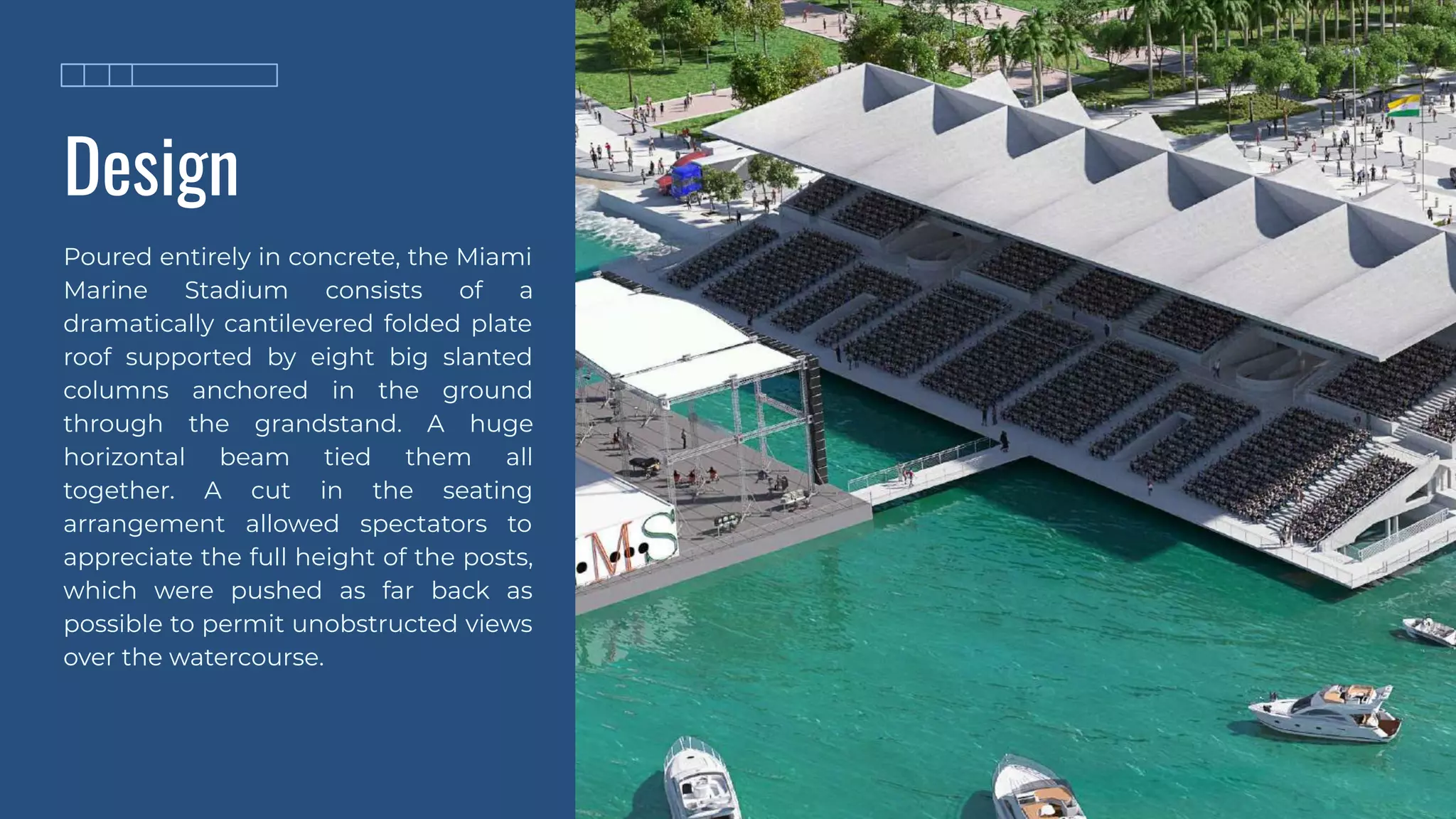
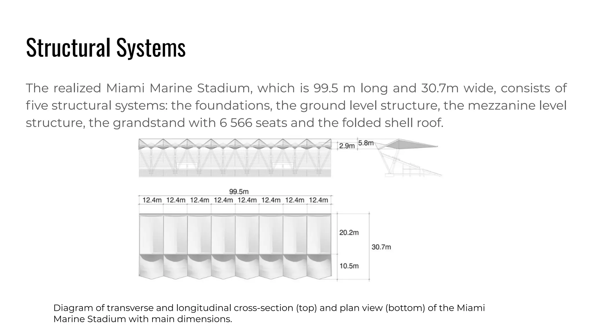
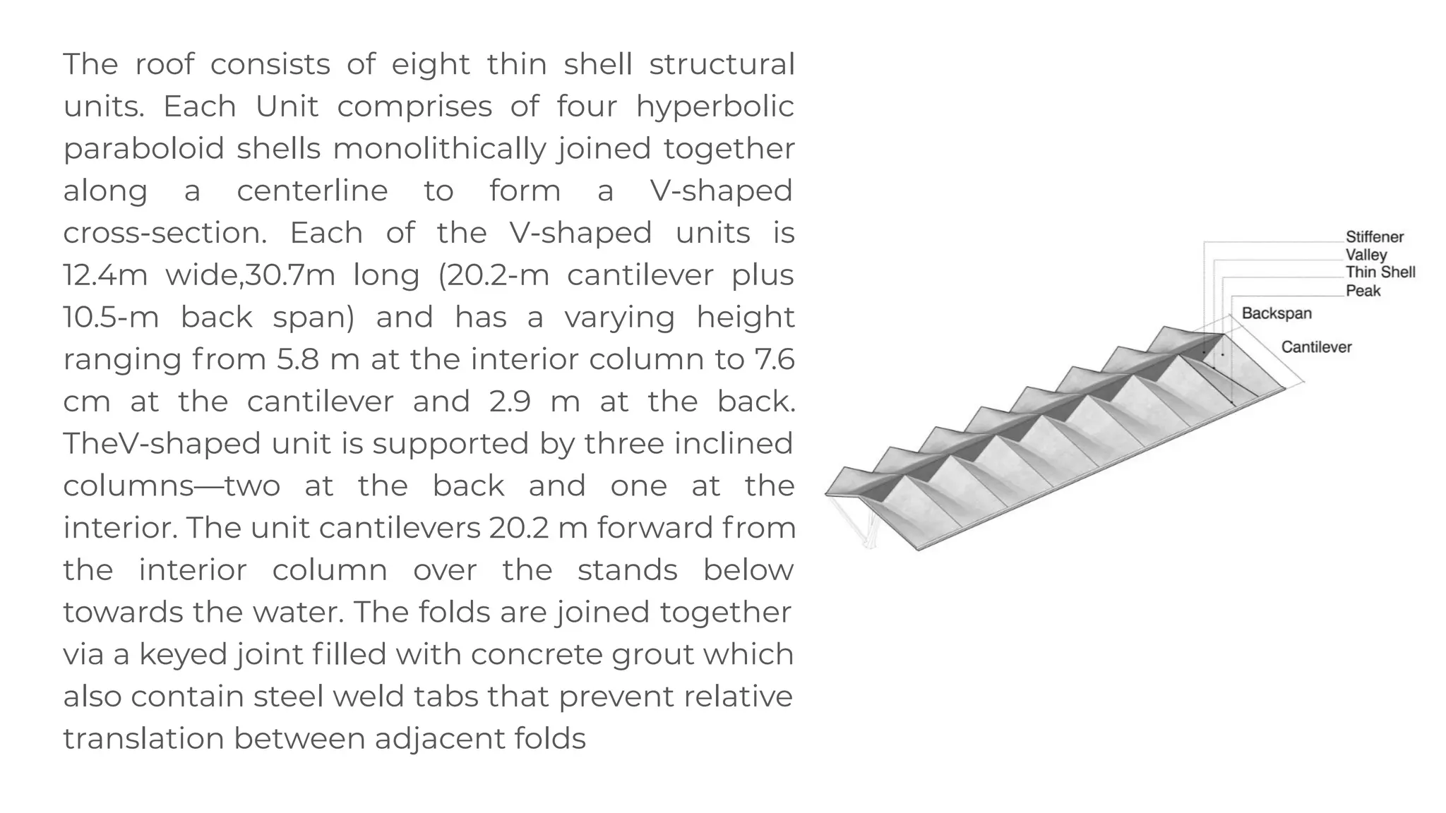
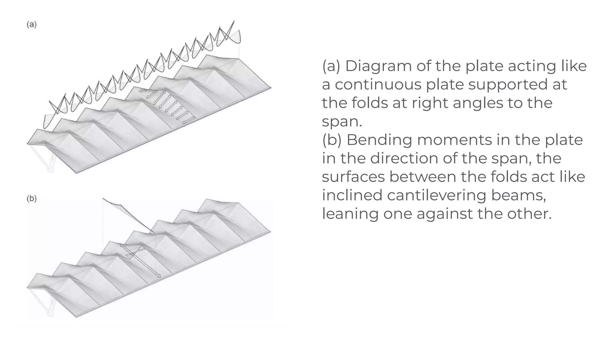
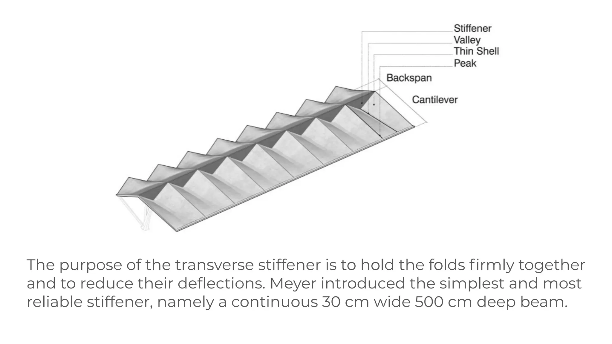
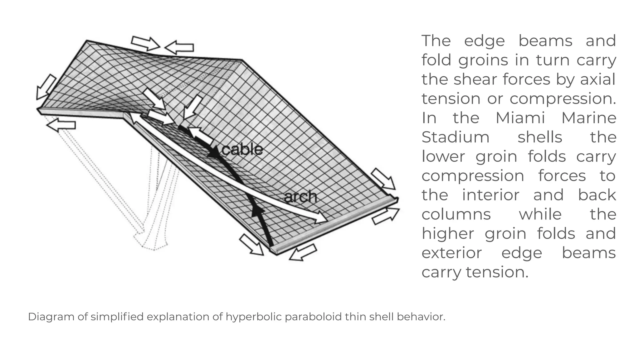
2. What are folded plate structures
Folded plates are assemblies of flat plates rigidly connected
together along their edges in such a way that the structural
system capable of carrying loads without the need for
additional supporting beams along mutual edges.
3. ● The pattern of the folding.
● Their geometrical basic shape.
● Its material.
● The connection of the different folding planes.
● The design of the bearings.
● Movable formwork can be employed.
● Form work required is relatively simpler.
● Design involves simpler calculations.
The structural characteristics of folding structures depend on:
4. The Miami Marine
Stadium
The Miami Marine Stadium is a
marine stadium on Virginia Key,
Miami, Florida, United States. The
facility, built and completed in
1963 by the Millman Construction
Company of Miami Beach, on land
donated to the City of Miami from
the Matheson family, is the first
stadium purpose-built for
powerboat racing in the United
States.
5. Design
Poured entirely in concrete, the Miami
Marine Stadium consists of a
dramatically cantilevered folded plate
roof supported by eight big slanted
columns anchored in the ground
through the grandstand. A huge
horizontal beam tied them all
together. A cut in the seating
arrangement allowed spectators to
appreciate the full height of the posts,
which were pushed as far back as
possible to permit unobstructed views
over the watercourse.
6. Structural Systems
The realized Miami Marine Stadium, which is 99.5 m long and 30.7m wide, consists of
five structural systems: the foundations, the ground level structure, the mezzanine level
structure, the grandstand with 6 566 seats and the folded shell roof.
Diagram of transverse and longitudinal cross-section (top) and plan view (bottom) of the Miami
Marine Stadium with main dimensions.
7. The roof consists of eight thin shell structural
units. Each Unit comprises of four hyperbolic
paraboloid shells monolithically joined together
along a centerline to form a V-shaped
cross-section. Each of the V-shaped units is
12.4m wide,30.7m long (20.2-m cantilever plus
10.5-m back span) and has a varying height
ranging from 5.8 m at the interior column to 7.6
cm at the cantilever and 2.9 m at the back.
TheV-shaped unit is supported by three inclined
columns—two at the back and one at the
interior. The unit cantilevers 20.2 m forward from
the interior column over the stands below
towards the water. The folds are joined together
via a keyed joint filled with concrete grout which
also contain steel weld tabs that prevent relative
translation between adjacent folds
8. One-way slab action between valley and ridge folds in the transverse
direction; This first assumption means that in the cantilevering part a
long and narrow 7.6-cm folded plate acts as a crimped continuous
slab spanning between nine high and eightlow folds spaced 6.2 m
apart in the roof’s transverse direction. In the back span the crimped
slab, whose thickness varies between 24 and 60 cm, can also be
understood as a continuous slab supported at the 17 fold lines.
Continuous slab approach reduces the total moments at the midspan
of the slab and generates negative bending moments at the folds.
Unlike most other folded plate systems, the transverse roof geometry
and the associated groin cross-section of the Miami Marine roof vary
from back span to end of the cantilevering tip
Folded-Plate Analysis
9. (a) Diagram of the plate acting like
a continuous plate supported at
the folds at right angles to the
span.
(b) Bending moments in the plate
in the direction of the span, the
surfaces between the folds act like
inclined cantilevering beams,
leaning one against the other.
10. The purpose of the transverse stiffener is to hold the folds firmly together
and to reduce their deflections. Meyer introduced the simplest and most
reliable stiffener, namely a continuous 30 cm wide 500 cm deep beam.
11. Each fold of the Miami Marine Stadium roof can be considered as being
composed of two sets of two hyperbolic paraboloid shells (thus 4 in total)
with a low interior support and two higher points. The hyperbolic paraboloid
thin concrete reinforced shell started to engage the engineering design
community around the same time that the folded plates made their
appearance. Their special geometric properties made these surfaces at first
sight easy to analyze and construct as they rely on straight line generators.
Hyperbolic parabolic shells can be visualized as two systems of arches, one
downward curving parabola in compression and one upward curving
parabola in tension. The arch forces are brought to the straight line edges (or
edge beams and groin folds in the case of the Miami Marine Stadium) where
the components perpendicular to these edgescancel and the components
parallel to the edges add to give shear forces along the edge beams and fold
groins.
Hyperbolic Paraboloid Shell Analysis
12. Diagram of simplified explanation of hyperbolic paraboloid thin shell behavior.
The edge beams and
fold groins in turn carry
the shear forces by axial
tension or compression.
In the Miami Marine
Stadium shells the
lower groin folds carry
compression forces to
the interior and back
columns while the
higher groin folds and
exterior edge beams
carry tension.
14. References
MIAMI MARINE STADIUM RESTORATION PROJECT
❏ https://www.jmsnet.com/2020/01/miami-marine-stadium-restoration-project/
Structural Analysis of Reinforced Concrete Folded Hyperbolic Paraboloid: A Case
Study of the Modern Miami Marine Stadium.
❏ https://www.researchgate.net/publication/254280273_Structural_Analysis_of_R
einforced_Concrete_Folded_Hyperbolic_Paraboloid_A_Case_Study_of_the_Mod
ern_Miami_Marine_Stadium