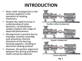
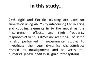
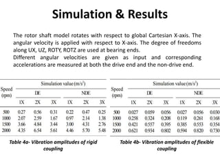
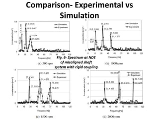
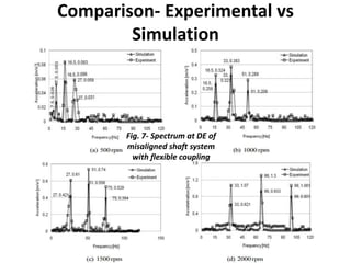
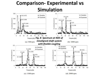
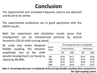
Vibration analysis of parallel
misaligned shaft with ball bearing
system
Presented by: Name
Submitted to: Prof. Name
INTRODUCTION
• Rotor shaft misalignment is the
common problem in the
operation of rotating
machinery.
• Despite the rapid increase in
understanding of rotor
dynamics, no satisfactory
analysis explains the range of
observed phenomena.
• Misalignment is present due to
improper machine assembly
and sometimes thermal
distortion of the bearing
housing supports, resulting in
abnormal rotating preload.
• However, the perfect alignment
between the driving and driven
shafts cannot be attained
Fig. 1
In this study…
Both rigid and flexible coupling are used for
simulation using ANSYS by introducing the bearing
and coupling elements in to the model as the
misalignment effects, and their frequency
responses at various RPMs are recorded. The same
is also performed in experimental studies to
investigate the rotor dynamics characteristics
related to misalignment and to verify the
numerically developed misaligned rotor systems.
Couplings
Rigid Coupling
• Has two flanges made of cast
iron, connected by means of
bolts. Shafts are rigidly connected
by the coupling through keys.
Flexible Coupling
• Consists of two flanges of different
geometry. Each has keyway to
accommodate the shaft rigidly with
the flange. One contains 3 equally
spaced blind holes at a pitch circle
diameter to engage the pin of the
other flange. Then, rubber bushes
are introduced in between to avoid
the metal to metal contact.
Fig. 2a- Rigid Coupling
Fig. 2b- Flexible Coupling
Experimental Setup
It consists of a DC motor, a pin type flexible coupling or rigid coupling, and an
over hung circular disc on the shaft.
The shaft of 19 mm diameter is supported by two identical ball bearings.
The bearing pedestals are provided in such a way as to adjust in vertical
direction to create necessary linear misalignment.
The shaft is driven by a 0.56 kW DC motor.
A DC voltage controller is used to adjust the power supply of the motor and it
can be operated at different speeds.
Fig. 3- Experimental
Setup
Experiment & Results
First, two shafts are connected by rigid coupling and bolts. Then, parallel
misalignment of 0.2 mm is created by adjusting the bearing pedestal in the
vertical direction. The dial gauge is used to measure the shaft
misalignment.
These vibration signals are measured at 4 different RPMs at both the drive
end(DE) and non-drive end(NDE).
Next, the rigid coupling is replaced by the flexible coupling and vibration
signals are recorded with same misalignment of 0.2mm for 4 different
RPMs.
Table 1a- Vibration amplitudes of rigid
coupling
Table 1b- Vibration amplitudes of flexible
coupling
Numerical Setup
Rotor shaft and couplings are modeled using
Pro/ Engineer wildfire-4 with the exact
dimensions as used in the experimental setup.
Using ANSYS, simulation is carried out.
Both rigid & flexible coupling are modeled and
analyzed.
Table 2- Material Properties
Table 3- Design parameters
Fig. 4- Rotor System with
boundary conditions
Simulation & Results
The rotor shaft model rotates with respect to global Cartesian X-axis. The
angular velocity is applied with respect to X-axis. The degree of freedoms
along UX, UZ, ROTY, ROTZ are used at bearing ends.
Different angular velocities are given as input and corresponding
accelerations are measured at both the drive end and the non-drive end.
Table 4a- Vibration amplitudes of rigid
coupling
Table 4b- Vibration amplitudes of flexible
coupling
Comparison- Experimental vs
Simulation
Fig. 5- Spectrum at DE of
misaligned shaft system
with rigid coupling
Comparison- Experimental vs
Simulation
Fig. 6- Spectrum at NDE
of misaligned shaft
system with rigid coupling
Comparison- Experimental vs
Simulation
Fig. 7- Spectrum at DE of
misaligned shaft system
with flexible coupling
Comparison- Experimental vs
Simulation
Fig. 8- Spectrum at NDE of
misaligned shaft system
with flexible coupling
Conclusion
The experimental and simulated frequency spectra are obtained
and found to be similar.
The experimental predictions are in good agreement with the
ANSYS results.
Both the experiment and simulation results prove that
misalignment can be characterized primarily by second
harmonics (2X) of shaft running speed.
By using new newly designed
flexible coupling, the vibration
amplitudes due to the shaft
parallel misalignment are found to
reduce by 85-89%.
Table 5- Percentage decrease in amplitude of the pin type flexible coupling when compared to
the rigid coupling system
Reference
[1] Vaggeeram Hariharan1 and PSS.Srinivasan, “Vibration analysis of
parallel misaligned shaft with ball bearing system”, Songklanakarin J. Sci.
Technol. 33 (1), 61-68, Jan. - Feb. 2011
[2] http://www.vibelube.com/1110alignments/
THANK YOU

Vibration analysis due to shaft misalignment

  • 1.
    Vibration analysis ofparallel misaligned shaft with ball bearing system Presented by: Name Submitted to: Prof. Name
  • 2.
    INTRODUCTION • Rotor shaftmisalignment is the common problem in the operation of rotating machinery. • Despite the rapid increase in understanding of rotor dynamics, no satisfactory analysis explains the range of observed phenomena. • Misalignment is present due to improper machine assembly and sometimes thermal distortion of the bearing housing supports, resulting in abnormal rotating preload. • However, the perfect alignment between the driving and driven shafts cannot be attained Fig. 1
  • 3.
    In this study… Bothrigid and flexible coupling are used for simulation using ANSYS by introducing the bearing and coupling elements in to the model as the misalignment effects, and their frequency responses at various RPMs are recorded. The same is also performed in experimental studies to investigate the rotor dynamics characteristics related to misalignment and to verify the numerically developed misaligned rotor systems.
  • 4.
    Couplings Rigid Coupling • Hastwo flanges made of cast iron, connected by means of bolts. Shafts are rigidly connected by the coupling through keys. Flexible Coupling • Consists of two flanges of different geometry. Each has keyway to accommodate the shaft rigidly with the flange. One contains 3 equally spaced blind holes at a pitch circle diameter to engage the pin of the other flange. Then, rubber bushes are introduced in between to avoid the metal to metal contact. Fig. 2a- Rigid Coupling Fig. 2b- Flexible Coupling
  • 5.
    Experimental Setup It consistsof a DC motor, a pin type flexible coupling or rigid coupling, and an over hung circular disc on the shaft. The shaft of 19 mm diameter is supported by two identical ball bearings. The bearing pedestals are provided in such a way as to adjust in vertical direction to create necessary linear misalignment. The shaft is driven by a 0.56 kW DC motor. A DC voltage controller is used to adjust the power supply of the motor and it can be operated at different speeds. Fig. 3- Experimental Setup
  • 6.
    Experiment & Results First,two shafts are connected by rigid coupling and bolts. Then, parallel misalignment of 0.2 mm is created by adjusting the bearing pedestal in the vertical direction. The dial gauge is used to measure the shaft misalignment. These vibration signals are measured at 4 different RPMs at both the drive end(DE) and non-drive end(NDE). Next, the rigid coupling is replaced by the flexible coupling and vibration signals are recorded with same misalignment of 0.2mm for 4 different RPMs. Table 1a- Vibration amplitudes of rigid coupling Table 1b- Vibration amplitudes of flexible coupling
  • 7.
    Numerical Setup Rotor shaftand couplings are modeled using Pro/ Engineer wildfire-4 with the exact dimensions as used in the experimental setup. Using ANSYS, simulation is carried out. Both rigid & flexible coupling are modeled and analyzed. Table 2- Material Properties Table 3- Design parameters Fig. 4- Rotor System with boundary conditions
  • 8.
    Simulation & Results Therotor shaft model rotates with respect to global Cartesian X-axis. The angular velocity is applied with respect to X-axis. The degree of freedoms along UX, UZ, ROTY, ROTZ are used at bearing ends. Different angular velocities are given as input and corresponding accelerations are measured at both the drive end and the non-drive end. Table 4a- Vibration amplitudes of rigid coupling Table 4b- Vibration amplitudes of flexible coupling
  • 9.
    Comparison- Experimental vs Simulation Fig.5- Spectrum at DE of misaligned shaft system with rigid coupling
  • 10.
    Comparison- Experimental vs Simulation Fig.6- Spectrum at NDE of misaligned shaft system with rigid coupling
  • 11.
    Comparison- Experimental vs Simulation Fig.7- Spectrum at DE of misaligned shaft system with flexible coupling
  • 12.
    Comparison- Experimental vs Simulation Fig.8- Spectrum at NDE of misaligned shaft system with flexible coupling
  • 13.
    Conclusion The experimental andsimulated frequency spectra are obtained and found to be similar. The experimental predictions are in good agreement with the ANSYS results. Both the experiment and simulation results prove that misalignment can be characterized primarily by second harmonics (2X) of shaft running speed. By using new newly designed flexible coupling, the vibration amplitudes due to the shaft parallel misalignment are found to reduce by 85-89%. Table 5- Percentage decrease in amplitude of the pin type flexible coupling when compared to the rigid coupling system
  • 14.
    Reference [1] Vaggeeram Hariharan1and PSS.Srinivasan, “Vibration analysis of parallel misaligned shaft with ball bearing system”, Songklanakarin J. Sci. Technol. 33 (1), 61-68, Jan. - Feb. 2011 [2] http://www.vibelube.com/1110alignments/
  • 15.