Downloaded 153 times
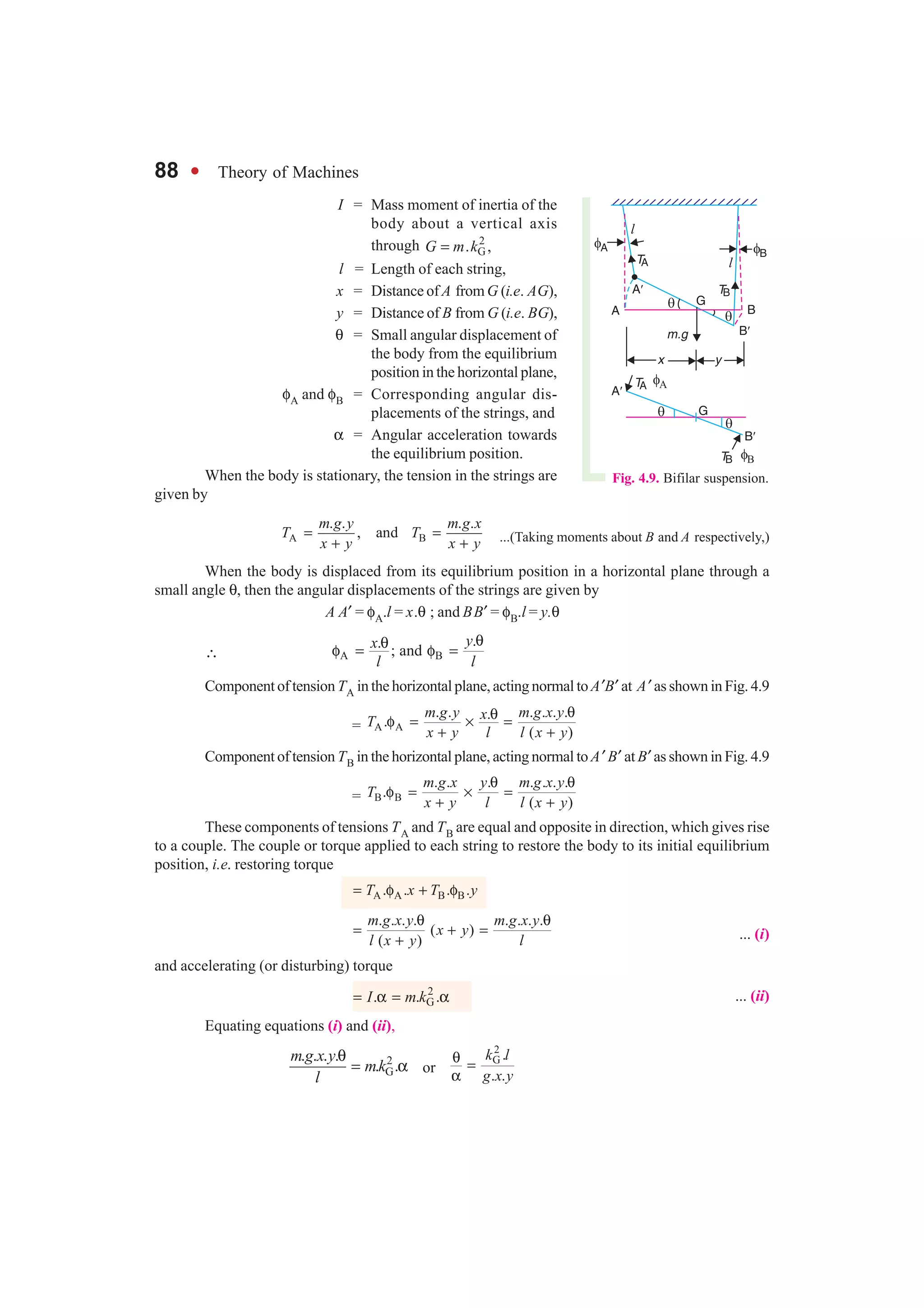
![74 l Theory of Machines
*
always directed towards the centre O; so that the motion of N is simple harmonic.
In general, a body is said to move or vibrate with simple harmonic motion, if it satisfies the
following two conditions :
1. Its acceleration is always directed towards the centre, known as point of reference or
mean position ;
2. Its acceleration is proportional to the distance from that point.
4.3. Differential Equation of Simple Harmonic Motion
We have discussed in the previous article that the displacement of N from its mean position O is
x = r.cos θ = r.cos ωt ... (i)
Differentiating equation (i), we have velocity of N,
N . sindx v r t
dt
= = ω ω ... (ii)
Again differentiating equation (ii), we have acceleration of N,
2
2 2
N2
. . cos . cos .
d x
a r t r t x
dt
= =− ω ω ω = − ω ω = − ω ... (iii)
... (3 r cos ωt = x)
or
2
2
2
0d x x
dt
+ ω =
This is the standard differential equation for simple harmonic motion of a particle. The
solution of this differential equation is
x = A cos ω t + B sin ω t ... (iv)
where A and B are constants to be determined by the initial conditions of the motion.
In Fig. 4.2, when t = 0, x = ri.e. when points P and N lie at X, we have from equation (iv), A = r
Differentiating equation (iv),
. .sin . cosdx A t B t
dt
= − ω ω + ω ω
When 0, 0,dxt
dt
= = therefore, from the above equation, B = 0. Now the equation (iv) becomes
x = r cos ω t . . . [Same as equation (i)]
The equations (ii) and (iii) may be written as
N . sin . cos ( / 2)dx v r t r t
dt
= = − ω ω = ω ω + π
and
2
2 2
N2
. cos . cos( )d x a r t r t
dt
= = − ω ω = ω ω + π
These equations show that the velocity leads the displacement by 90° and acceleration leads
the displacement by 180°.
* The negative sign shows that the direction of acceleration is opposite to the direction in which x increases,
i.e. the acceleration is always directed towards the point O.](https://image.slidesharecdn.com/simpleharmonicmotion-130530055733-phpapp02/75/Simple-harmonic-motion-3-2048.jpg)
![Chapter 4 : Simple Harmonic Motion l 81
Notes : 1. Comparing this equation with equation (ii) of simple pendulum, we see that the equivalent length of
a simple pendulum, which gives the same frequency as compound pendulum, is
2 2 2
G Gk h k
L h
h h
+
= = +
2. Since the equivalent length of simple pendulum (L) depends upon the distance between the point of
suspension and the centre of gravity (G), therefore L can be changed by changing the position of point of suspen-
sion. This will, obviously, change the periodic time of a compound pendulum. The periodic time will be minimum
if L is minimum. For L to be minimum, the differentiation of L with respect to h must be equal to zero, i.e.
2
G
0 or 0
kdL d h
dh dh h
= + =
∴
2
G
2
1 0
k
h
−
+ = or kG = h
Thus the periodic time of a compound pendulum is minimum when the distance between the point of
suspension and the centre of gravity is equal to the radius of gyration of the body about its centre of gravity.
∴ Minimum periodic time of a compound pendulum,
G
( )
2
2p min
k
t
g
= π . . . [Substituting h = kG in equation (i)]
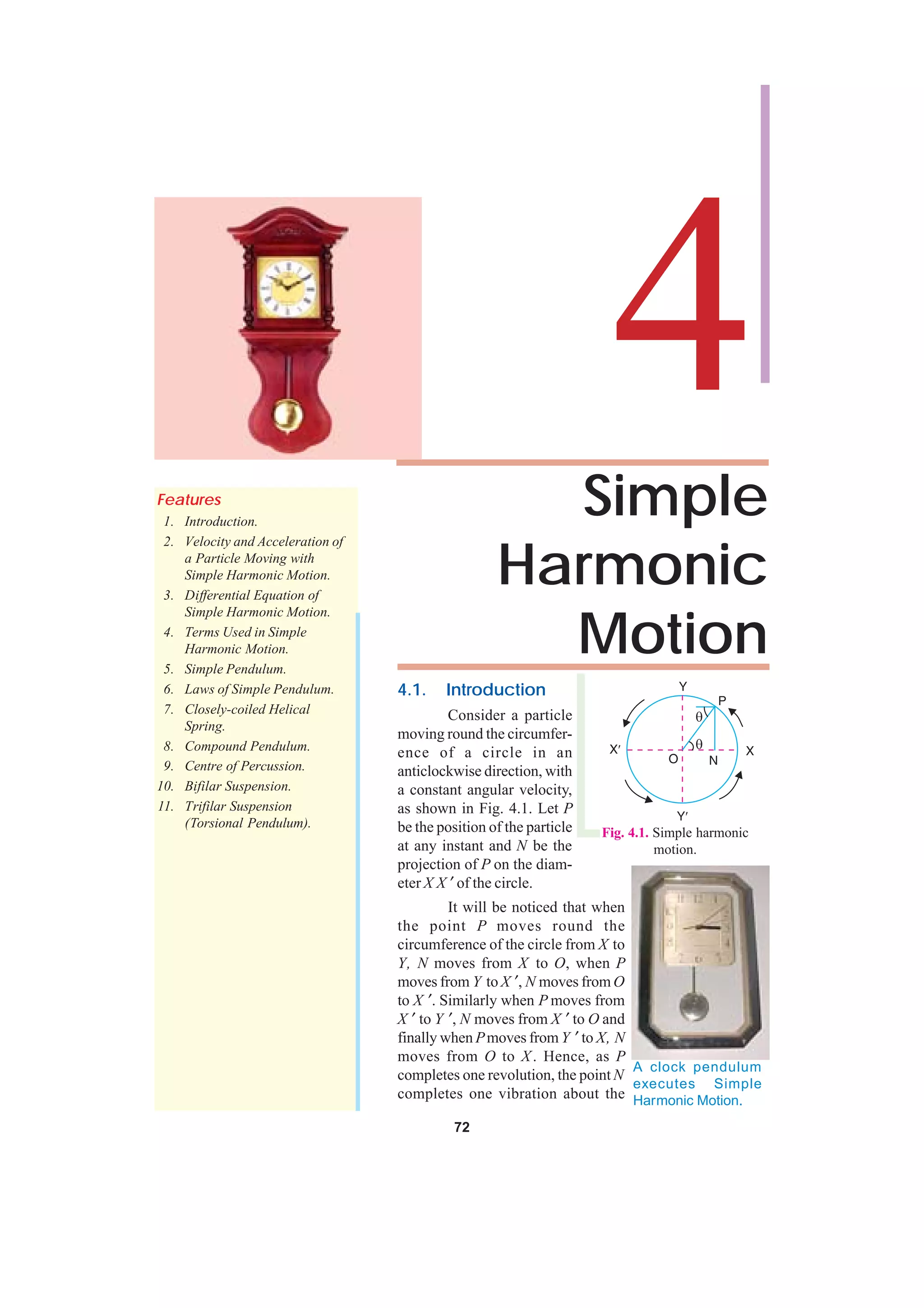
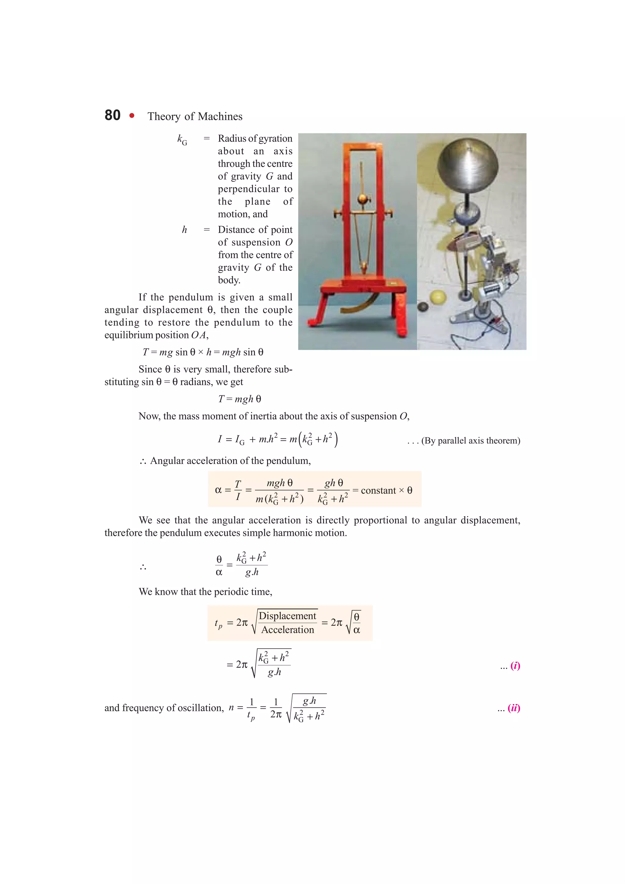
4.9. Centre of Percussion
The centre of oscillation is sometimes termed as cen-
tre of percussion. It is defined as that point at which a blow
may be struck on a suspended body so that the reaction at the
support is zero.
Consider the case of a compound pendulum suspended
at O as shown in Fig. 4.6. Suppose the pendulum is at rest in
the vertical position, and a blow is struck at a distance L from
the centre of suspension. Let the magnitude of blow is F new-
tons. A little consideration will show that this blow will have
the following two effects on the body :
1. A force (F) acting at C will produce a linear motion
with an acceleration a, such that
F = m.a ... (i)
where m is the mass of the body.
2. A couple with moment equal to (F × l ) which will tend to produce a motion of rotation in
the clockwise direction about the centre of gravity G. Let this turning moment (F × l) produce an
angular acceleration (α), such that
F × l = IG × α ... (ii)
where IG is the moment of inertia of the body about an axis passing through G and parallel to the axis
of rotation.
From equation (i) a = F/m ... (iii)
and from equation (ii),
G
.F l
I
α =
Fig. 4.6. Centre of percusssion.](https://image.slidesharecdn.com/simpleharmonicmotion-130530055733-phpapp02/75/Simple-harmonic-motion-10-2048.jpg)

![Chapter 4 : Simple Harmonic Motion l 91
We know that frequency of oscillation (n),
G G G
5 0.25 9.81 0.079
17 2 2 2.5
r g
k l k k
= = =
π π
∴ kG = 0.079 × 17/5 = 0.268 m = 268 mm Ans.
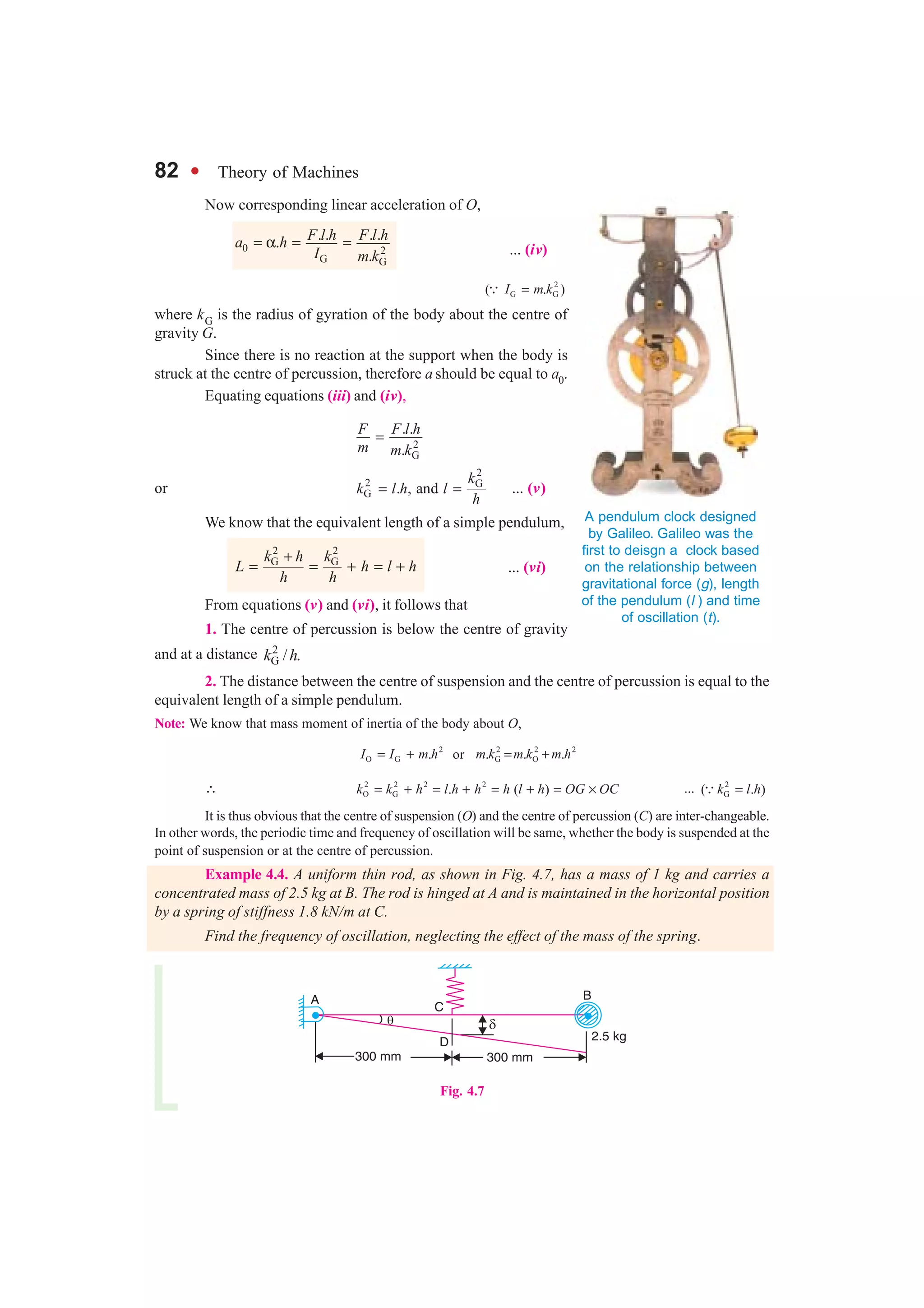
Example 4.11. A connecting rod of mass 5.5 kg is placed on a horizontal platform whose
mass is 1.5 kg. It is suspended by three equal wires, each 1.25 m long, from a rigid support. The wires
are equally spaced round the circumference of a circle of 125 mm radius. When the c.g. of the
connecting rod coincides with the axis of the circle, the platform makes 10 angular oscillations in 30
seconds. Determine the mass moment of inertia about an axis through its c.g.
Solution. Given : m1 = 5.5 kg ; m2 = 1.5 kg ; l = 1.25 m ; r = 125 mm = 0.125 m
Since the platform makes 10 angular oscillations in 30 s, therefore frequency of oscillation,
n = 10/30 = 1/3 Hz
Let kG = Radius of gyration about an axis through the c.g.
We know that frequency of oscillation (n)
G G G
1 0.125 9.81 0.056
3 2 2 1.25
gr
k l k k
= = =
π π
∴ kG = 0.056 × 3 = 0.168 m
and mass moment of inertia about an axis through its c.g.,
2 2 2 2
G 1 2 G. ( ) (5.5 1.5) (0.168) kg-mI m k m m k= = + = +
= 0.198 kg-m2 Ans.
EXERCISES
1. A particle, moving with simple harmonic motion, performs 10 complete oscillations per minute and
its speed, when at a distance of 80 mm from the centre of oscillation is 3/5 of the maximum speed.
Find the amplitude, the maximum acceleration and the speed of the particle, when it is 60 mm from
the centre of the oscillation. [Ans. 100 mm ; 109.6 mm/s2 ; 83.76 mm/s]
2. A piston, moving with a simple harmonic motion, has a velocity of 8 m/s, when it is 1 metre from the
centre position and a velocity of 4 m/s, when it is 2 metres from the centre. Find : 1. Amplitude, 2.
Periodic time, 3. Maximum velocity, and 4. Maximum acceleration.
[Ans. 2.236 m ; 1.571 s ; 8.94 m/s ; 35.77 m/s2]
3. The plunger of a reciprocating pump is driven by a crank of radius 250 mm rotating at 12.5 rad/s.
Assuming simple harmonic motion, determine the maximum velocity and maximum acceleration of
the plunger. [Ans. 3.125 m/s ; 39.1 m/s2]
4. A part of a machine of mass 4.54 kg has a reciprocating motion which is simple harmonic in character.
It makes 200 complete oscillations in 1 minute. Find : 1. the accelerating force upon it and its velocity
when it is 75 mm, from midstroke ; 2. the maximum accelerating force, and 3. the maximum velocity
if its total stroke is 225 mm i.e. if the amplitude of vibration is 112.5 mm.
[Ans. 149.5 N ; 1.76 m/s ; 224 N ; 2.36 m/s]
5. A helical spring of negligible mass is required to support a mass of 50 kg. The stiffness of the spring
is 60 kN/m. The spring and the mass system is displaced vertically by 20 mm below the equilibrium
position and then released. Find : 1. the frequency of natural vibration of the system ; 2. the velocity
and acceleration of the mass when it is 10 mm below the rest position.
[Ans. 5.5 Hz ; 0.6 m/s ; 11.95 m/s2]
6. A spring of stiffness 2 kN/m is suspended vertically and two equal masses of 4 kg each are attached to
the lower end. One of these masses is suddenly removed and the system oscillates. Determine : 1. the
amplitude of vibration, 2. the frequency of vibration, 3. the velocity and acceleration of the mass when](https://image.slidesharecdn.com/simpleharmonicmotion-130530055733-phpapp02/75/Simple-harmonic-motion-20-2048.jpg)
![92 l Theory of Machines
passing through half amplitude position, and 4. kinetic energy of the vibration in joules.
[Ans. 0.019 62 m ; 3.56 Hz ; 0.38 m/s , 4.9 m/s2 ; 0.385 J]
7. A vertical helical spring having a stiffness of 1540 N/m is clamped at its upper end and carries a mass
of 20 kg attached to the lower end. The mass is displaced vertically through a distance of 120 mm and
released. Find : 1. Frequency of oscillation ; 2. Maximum velocity reached ; 3. Maximum accelera-
tion; and 4. Maximum value of the inertia force on the mass.
[Ans. 1.396 Hz ; 1.053 m/s ; 9.24 m/s2 ; 184.8 N]
8. A small flywheel having mass 90 kg is suspended in a vertical plane as a compound pendulum. The
distance of centre of gravity from the knife edge support is 250 mm and the flywheel makes 50
oscillations in 64 seconds. Find the moment of inertia of the flywheel about an axis through the centre
of gravity. [Ans. 3.6 kg-m2]
9. The connecting rod of a petrol engine has a mass 12 kg. In order to find its moment of inertia it is
suspended from a horizontal edge, which passes through small end and coincides with the small end
centre. It is made to swing in a vertical plane, such that it makes 100 oscillations in 96 seconds. If the
point of suspension of the connecting rod is 170 mm from its c.g., find : 1. radius of gyration about an
axis through its c.g., 2. moment of inertia about an axis through its c.g., and 3. length of the equivalent
simple pendulum. [Ans. 101 mm ; 0.1224 kg-m2 ; 0.23 m]
10. A connecting rod of mass 40 kg is suspended vertically as a compound pendulum. The distance between
the bearing centres is 800 mm. The time for 60 oscillations is found to be 92.5 seconds when the axis of
oscillation coincides with the small end centre and 88.4 seconds when it coincides with the big end
centre. Find the distance of the centre of gravity from the small end centre, and the moment of inertia of
the rod about an axis through the centre of gravity. [Ans. 0.442 m ; 2.6 kg-m2]
11. The following data were obtained from an experiment to find the moment of inertia of a pulley by
bifilar suspension :
Mass of the pulley = 12 kg ; Length of strings = 3 m ; Distance of strings on either side of centre of
gravity = 150 mm ; Time for 20 oscillations about the vertical axis through c.g. = 46.8 seconds
Calculate the moment of inertia of the pulley about the axis of rotation.
[Ans. 0.1226 kg-m2]
12. In order to find the moment of inertia of a flywheel, it is suspended in the horizontal plane by three
wires of length 1.8 m equally spaced around a circle of 185 mm diameter. The time for 25 oscillations
in a horizontal plane about a vertical axis through the centre of flywheel is 54 s. Find the radius of
gyration and the moment of inertia of the flywheel if it has a mass of 50 kg.
[Ans. 74.2 mm; 0.275 kg-m2]
DO YOU KNOW ?
1. Explain the meaning of S.H.M. and give an example of S.H.M.
2. Define the terms amplitude, periodic time, and frequency as applied to S.H.M.
3. Show that when a particle moves with simple harmonic motion, its time for a complete
oscillation is independent of the amplitude of its motion.
4. Derive an expression for the period of oscillation of a mass when attached to a helical spring.
5. What is a simple pendulum ? Under what conditions its motion is regarded as simple harmonic?
6. Prove the formula for the frequency of oscillation of a compound pendulum. What is the length of a
simple pendulum which gives the same frequency as compound pendulum ?
7. Show that the minimum periodic time of a compound pendulum is
G
( )
2
2p min
k
t
g
= π
where kG is the radius of gyration about the centre of gravity.
8. What do you understand by centre of percussion ? Prove that it lies below the centre of gravity of the
body and at a distance 2
G /k h , where kG is the radius of gyration about c.g. and h is the distance
between the centre of suspension and centre of gravity.](https://image.slidesharecdn.com/simpleharmonicmotion-130530055733-phpapp02/75/Simple-harmonic-motion-21-2048.jpg)

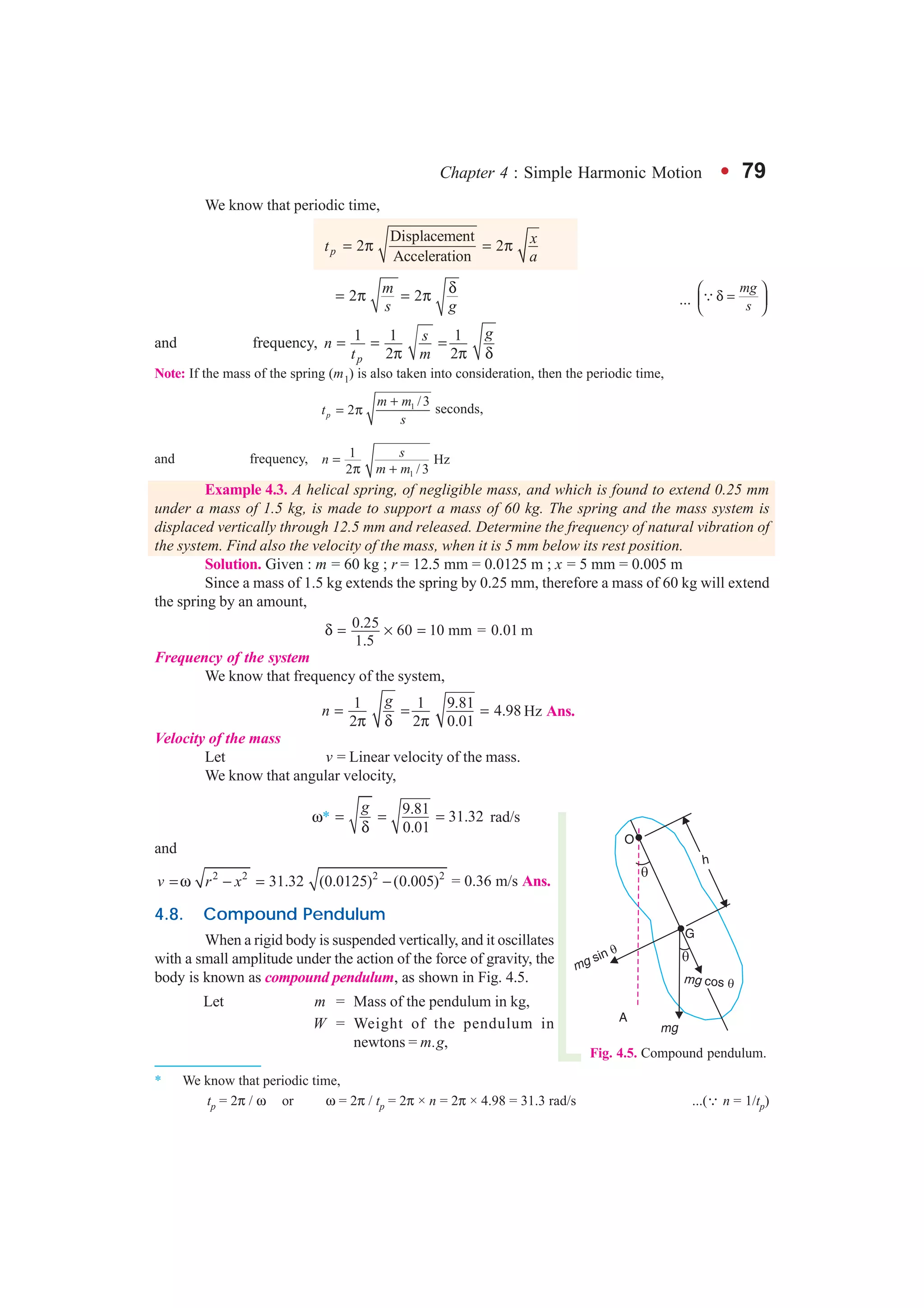
This document discusses simple harmonic motion. It begins by introducing simple harmonic motion as the to-and-fro motion of a particle vibrating about a central mean position. It then provides the differential equation that describes simple harmonic motion and discusses key terms like amplitude, period, and frequency. The document also examines simple harmonic motion in pendulums, springs, and other contexts, establishing various governing laws and relationships.