Fluid Machine forChemical
Engineers(Cheg2101)
CHAPTER ONE : Introduction
1
2.
Chapter topics tobe covered
1. Introduction
1.1 Identify objective of this chapter
1.2 Define fluid Machines & Know types of fluid
Machines in Chemical Process Industries
1.3 Basic Concepts andTerminologies
1.4.Application of Fluid Machines
2
3.
At endof this chapter students’ shall be able to:
Identify the purpose of learning fluid machines and their applications in
process industries,
Recognize the role of chemical engineers with respect to fluid machines,
Determine the specific work, total head, total pressure and useful power for
fluid machines.
3
1.1 Objectives
4.
1.2 Definition
Fluid Machines:devices that are used to raise, transfer or
compress liquids or gases.
Fluid machines can be pumps, fans, blowers and
compressors.
Pumps: fluid machines that are used to transport
liquids by increasing the mechanical energy of liquids.
Fans, blowers and compressors: fluid machines that are
used to transport gases by increasing the mechanical
energy of gases.
4
5.
Cont’d
Fans: fluidmachines that are used in ventilating
working stations, introducing air into reactors or
exhaust gases at low pressure.
Blowers: machines that are used to compress gases at
low pressure to supply air or exhaust gases.
Compressor: machines that are used to compress
gases at high pressure to supply air combustion
processes.
5
6.
Fluid Machines inChemical Process Industries
In chemical process industries, it is usually required to
increase the mechanical energy of fluids.
Mechanical energy includes potential energy, velocity
energy, pressure energy and losses due to fluid friction.
6
7.
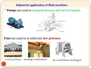
Pumps are usedto transport process and service liquids.
Fans are used in at relatively low pressure
Industrial application of fluid machines
7
ventilating buildings aerating workstations air-cooled heat exchangers
8.
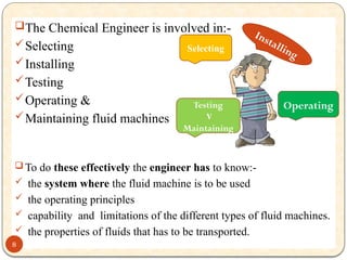
The Chemical Engineeris involved in:-
Selecting
Installing
Testing
Operating &
Maintaining fluid machines
To do these effectively the engineer has to know:-
the system where the fluid machine is to be used
the operating principles
capability and limitations of the different types of fluid machines.
the properties of fluids that has to be transported.
Selecting
Operating
Testing
V
Maintaining
Installing
8
9.
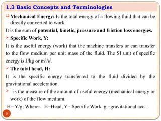
Mechanical Energy:Is the total energy of a flowing fluid that can be
directly converted to work.
It is the sum of potential, kinetic, pressure and friction loss energies.
Specific Work, Y:
It is the useful energy (work) that the machine transfers or can transfer
to the flow medium per unit mass of the fluid. The SI unit of specific
energy is J/kg or m2
/s2
.
The total head, H:
It is the specific energy transferred to the fluid divided by the
gravitational acceleration.
is the measure of the amount of useful energy (mechanical energy or
work) of the flow medium.
H= Y/g; Where:- H=Head, Y= Specific Work, g =gravitational acc.
1.3 Basic Concepts and Terminologies
9
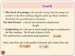
10.
The headof a pump is the specific energy that the pump can
transfer to the flow medium (liquid) under specified condition
divided by the gravitational acceleration.
The Total Pressure: Used for fans and positive displacement
Pt=ρY
Useful Power, N :- the rate at which useful energy is transferred to
the flow medium. The SI unit of power is kJ/s
The useful power is calculated using Equations:
Since mass flow rate is the product of density and volume flow rate.
Y
m
N
QY
N
Cont’d
N = QPt
10
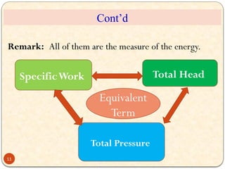
11.
Remark: All ofthem are the measure of the energy.
SpecificWork Total Head
Total Pressure
Equivalent
Term
Cont’d
11
12.
Cont’d
Pulsation:-
The capacity ofsome fluid machines is not uniform, it varies
with time. Pulsation is this non uniformity of the capacity
fluid machines.
Priming:-
Some pumps require that the air in the suction line should
be replaced by liquid before they start pumping. The process
of replacing the air in the suction pipe with liquid is known
as priming.
Loss of Head:
is loss of the useful head of the flow medium due to fluid
friction or the turbulence that occurs when the fluid passes
an obstruction, sudden contraction or sudden expansion, etc.
12
13.
Pressure
Absolute pressure (static)of a fluid on a surface is the
normal force exerted by the fluid per unit area of the surface.
Gauge Pressure is the pressure above the atmospheric
pressure.
Absolute Pressure = Gauge Pressure + Atmospheric Pressure
Vacuum Pressure is the pressure below the atmospheric
pressure.
Absolute Pressure = Atmospheric Pressure - Vacuum Pressure
13
14.
Mass balancefor a steady state process (no accumulation)
Rate of mass input = Rate of mass output
For incompressible fluid
Where :-Q=Volume flow rate [m3
/s],
C = velocity of the flow medium(m/s),A= Flow Area(m2
)
;
2
2
1
1 Q
Q
m
c
A
c
A
m 2
2
2
1
1
1
2
2
1
1 c
A
c
A
rate(kg/s)
flow
mass
m
14
Process
A1
A2
Input output
Figure: The continuity equation
15.
1.4 Application ofFluid Machines
15
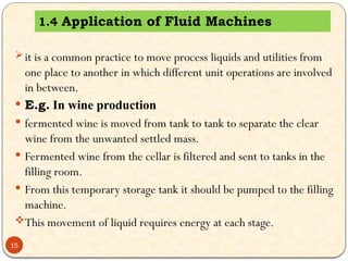
it is a common practice to move process liquids and utilities from
one place to another in which different unit operations are involved
in between.
E.g. In wine production
fermented wine is moved from tank to tank to separate the clear
wine from the unwanted settled mass.
Fermented wine from the cellar is filtered and sent to tanks in the
filling room.
From this temporary storage tank it should be pumped to the filling
machine.
This movement of liquid requires energy at each stage.
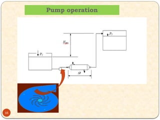
The amountof specific energy required by a flow
medium
where:- Y= The specific energy
P2 - P1= The static pressure difference between the suction
and discharge
c1, c2 = The average flow velocities at point 1 and 2
respectively.
e = the elevation difference between 1 and 2.
F = specific energy loss due to fluid friction
= Density of the flow medium at the flow condition
cont’d
17
18.
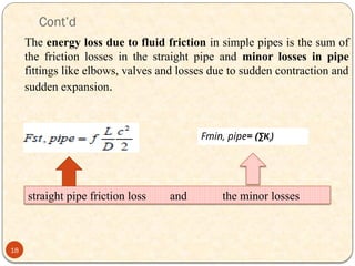
Cont’d
The energy lossdue to fluid friction in simple pipes is the sum of
the friction losses in the straight pipe and minor losses in pipe
fittings like elbows, valves and losses due to sudden contraction and
sudden expansion.
straight pipe friction loss and the minor losses
18
Fmin, pipe= (∑Ki)
19.
19
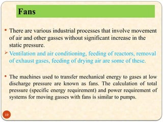
There arevarious industrial processes that involve movement
of air and other gasses without significant increase in the
static pressure.
Ventilation and air conditioning, feeding of reactors, removal
of exhaust gases, feeding of drying air are some of these.
The machines used to transfer mechanical energy to gases at low
discharge pressure are known as fans. The calculation of total
pressure (specific energy requirement) and power requirement of
systems for moving gasses with fans is similar to pumps.
Fans
20.
Example 1.1
Waterat 200
C should be pumped from Tank 1 to Tank 2 at the rate of
120m3
/hr. All pipes in the system are with diameter of 0.1541m. The
total length of the straight pipe is 45m. Determine the specific
mechanical energy, head and power that should be transferred to the flow
medium to move the water. (Use water at 200
C ρ =998.2 kg/m3
, μ=1.005
*10-3
Pa. s; and pipe roughness, ε=4.6 *10 -5
,k of 900
elbow =0.64)
20
21.
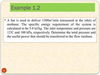
A fanis used to deliver 1300m3
/min (measured at the inlet) of
methane. The specific energy requirement of the system is
calculated to be 5.4 kJ/kg. The inlet temperature and pressure are
12o
C and 100 kPa, respectively. Determine the total pressure and
the useful power that should be transferred to the flow medium.
Example 1.2
21
22.
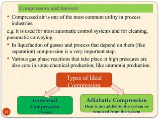
Compressors and blowers
Compressed air is one of the most common utility in process
industries.
e.g. it is used for most automatic control systems and for cleaning,
pneumatic conveying.
In liquefaction of gasses and process that depend on them (like
separation) compression is a very important step.
Various gas phase reactions that take place at high pressures are
also core in some chemical production, like ammonia production.
Isothermal
Compression
T=const
Adiabatic Compression
Heat is not added to the system or
removed from the system
Types of Ideal
Compression
22
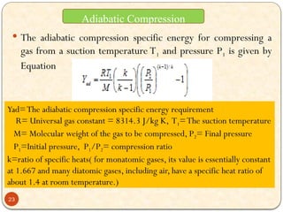
23.
The adiabaticcompression specific energy for compressing a
gas from a suction temperature T1 and pressure P1 is given by
Equation
Yad=The adiabatic compression specific energy requirement
R= Universal gas constant = 8314.3 J/kg K, T1=The suction temperature
M= Molecular weight of the gas to be compressed, P2= Final pressure
P1=Initial pressure, P1/P2= compression ratio
k=ratio of specific heats( for monatomic gases, its value is essentially constant
at 1.667 and many diatomic gases, including air, have a specific heat ratio of
about 1.4 at room temperature.)
Adiabatic Compression
23
24.
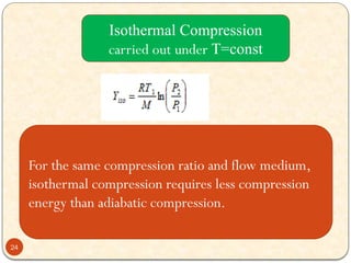
For the samecompression ratio and flow medium,
isothermal compression requires less compression
energy than adiabatic compression.
Isothermal Compression
carried out under T=const
24
25.
Example 1.3
Itis required to compress 0.02 k mol/s of air from 1 atm and
250
C to 6 atm. Calculate the specific energy requirement
and the compression power.(take Mwt of air =28.9 kg/kmol
(i) for adiabatic compression
(ii) for isothermal compression.
25

![ Mass balance for a steady state process (no accumulation)
Rate of mass input = Rate of mass output
For incompressible fluid
Where :-Q=Volume flow rate [m3
/s],
C = velocity of the flow medium(m/s),A= Flow Area(m2
)
;
2
2
1
1 Q
Q
m
c
A
c
A
m 2
2
2
1
1
1
2
2
1
1 c
A
c
A
rate(kg/s)
flow
mass
m
14
Process
A1
A2
Input output
Figure: The continuity equation](https://image.slidesharecdn.com/fmchapter1-250222092507-84f0e9f3/85/Fluid-Machine-Chapter-1-my-presentation-pptx-14-320.jpg)